Week-6 Challenge: EV Drivetrain
1.
Power electronic converters are used everywhere in normal daily routines at home, commercial workplaces or in an industrial environment.
Due to the high-power handling with higher efficiencies, these converters become an integral part of industrial electric drives, electric & hybrid electric vehicles, high electric power supplies, electric traction systems and automobile control equipment’s.
There are different types of power electronic converters used for performing different functions (such as inversion, rectification, etc.) which are rated from a few milliwatts to a few thousand watts.
A power electronic converter uses power electronic components such as SCRs, TRIACs, IGBTs, etc. To control and convert the electric power. The main aim of the converter is to produce conditioning power with respect to a certain application.
Types of power converters used in electric and hybrid electric vehicle are
1.AC to DC Converters
2.DC to AC Converters
3.DC to DC Converters
4.AC to AC Converters
AC to DC Converters:
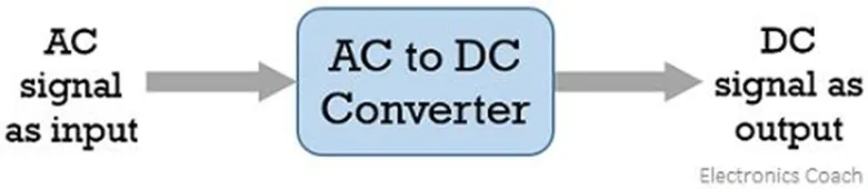
A type of converter that changes input AC signal into a DC is known as AC to DC converter. We have already learned in basic electronics that the devices that convert the AC signal into DC signal are known as rectifiers.
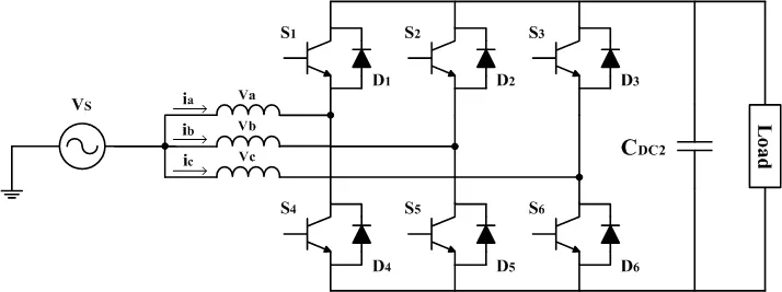
AC to DC Converter is further classified as:
- Diode Rectifiers
- Phase Controlled Rectifiers
DC to AC Converters
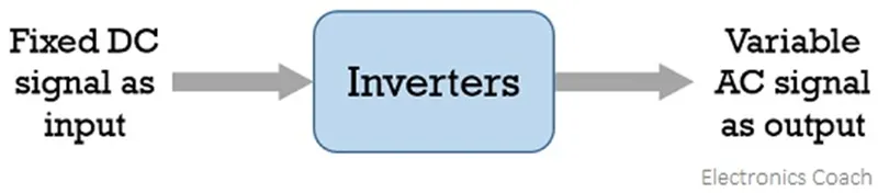
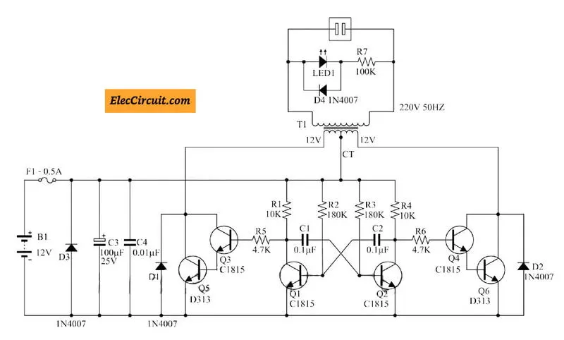
The devices that are designed to convert the dc signal into ac signal are known as inverters. The applied input is a fixed dc voltage that can be obtained from batteries but the output obtained is variable ac voltage. The voltage and frequency of the signal obtained are of variable nature. Here the semiconductor device i.e., the thyristor is turned off by using either line, load, or forced commutation.
Thus, it can be said that by the use of inverters, a fixed dc voltage is changed into an ac voltage of variable frequency. Generally, the semiconductor devices used for its fabrication are power transistors, MOSFETs, IGBT, GTO, thyristors, etc.
Inverters mainly find applications in induction motor and synchronous motor drives along with UPS, aircraft, and space power supplies. In high voltage dc transmission system, induction heating supplies as well as low power systems of mobile nature like flashlight discharge system in photography camera to very high-power industrial system.
Like choppers, in inverters also conventional thyristors are used in high power applications and power transistors are used in low power applications.
DC to DC Converters
The converters that convert the dc signal of fixed frequency present at the input into a variable dc signal at the output are also known as choppers. Here the achieved output dc voltage may have a different amplitude than the source voltage. Generally, power transistors, MOSFETs, and thyristors are the semiconductor devices used for their fabrication. The output is controlled by a low power signal that controls these semiconductor devices from a control unit.
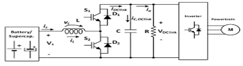
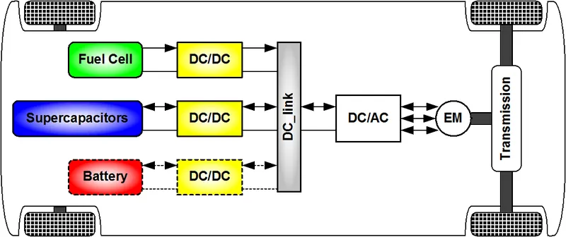
Here forced commutation is required to turn off the semiconductor device. Generally, in low power circuits power transistors are used while in high power circuits thyristors are used.
DC-DC Converters are further classified as,
Step-down Chopper or Buck converter
A step-down chopper produces an average output voltage lower than the input DC voltage. The circuit for this converter is shown in figure below.
Here the switching component is a thyristor that switches the input voltage to the load when it is triggered at particular instants.
A diode acts as a free wheeling diode that allows the load current to flow through it when thyristor is turned OFF. If this diode is absent, a high induced EMF in inductance may cause damage to the switching device.
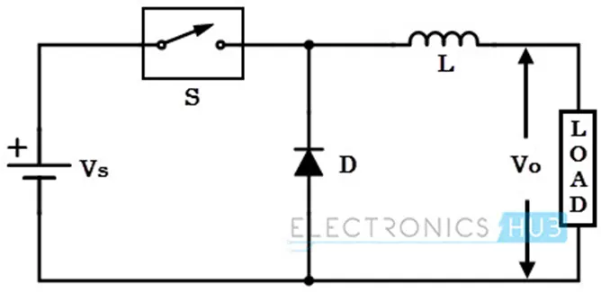
The average output voltage of the converter is varied by controlling turn ON/OFF periods of thyristor. When thyristor is turned ON, the output voltage is same as the input voltage and if it is turned OFF, the output voltage is zero.
The output voltage is equal to (TON / T) Vin. So, by controlling the duty ratio K = (TON / T), the output voltage will be increased.
Step-up Chopper or Boost converter
In this chopper, the output voltage is always greater than input voltage. The configuration of a boost converter is shown in figure below.
Here also a switch is used, which is connected in parallel with the load. This switch is a thyristor or an SCR.
As similar to the buck converter, a diode is placed in series with the load that allows the load current to flow when the thyristor is turned OFF.
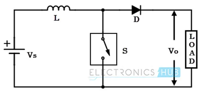
When the thyristor is turned ON, the diode is reverse-biased and hence it isolates the load circuit from the source. So the inductor charges to the maximum input voltage source.
When the thyristor is turned OFF, the load gets the voltage from input as well as from inductor. So the voltage appearing across the converter output will be more than the input.
Here the output voltage is equal to (1/ 1 – d) times the input voltage, where d is the duty ratio (TON / T). By varying this duty ratio, the output voltage will be varied till the load gets desired voltage.
Buck/Boost converter
This chopper can be used both in step-down and step-up modes by continuously adjusting its duty cycle. The configuration of buck-boost converter is shown in figure below that consists of only one switching device, i.e., one thyristor.
Along with an inductor and diode, additional capacitor is connected in parallel with this circuit.
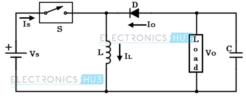
When the thyristor is turned ON, the supply current flows to the inductor through the thyristor and induces the voltage in inductor.
When the thyristor is OFF, the current in the inductor tends to decrease with the induced emf reversing polarity. The output voltage of this converter remains constant as capacitor is connected across the load.
By varying the value of duty ratio to a certain value, the output voltage is lower than the input voltage, typically in the range 0 ≥ k > 0.5, thus a buck converter.
And the output is higher than the input voltage if the duty ratio is in the range of 0.5 > K ≥ 1, thus acts as a boost converter.
AC to AC Converters
An ac to ac converter is designed to change the ac signal of fixed frequency into a variable ac output voltage.
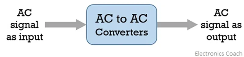
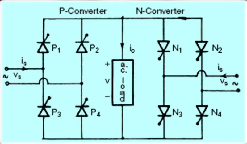
There are two classifications of ac to ac converters which are as follows:
Cycloconverters:
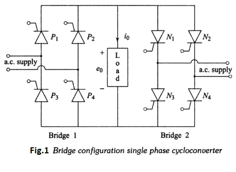
A cycloconverter is a device used for changing ac supply of fixed voltage and single frequency into an ac output voltage of variable voltage as well as different frequency. However, here the obtained variable ac signal frequency is lower than the frequency of the applied ac input signal. It adopts single-stage conversion. Generally, line commutation is mostly used in cycloconverters however forced or load commutated cycloconverters are also used in various applications.
These mainly find applications in slow-speed large AC traction drives such as a rotary kiln, multi MW ac motor drives, etc.
AC Voltage Controllers (AC voltage regulators): The converters designed to change the applied ac signal of fixed voltage into a variable ac voltage signal of the same frequency as that of input. For the operation of these controllers, two thyristors in an antiparallel arrangement are used. Line commutation is used for turning off both the devices. It offers the controlling of the output voltage by changing the firing angle delay.
The major applications of ac voltage controllers are in lighting control, electronic tap changers, speed control of large fans and pumps as well.
2.
Motor and controller parameters:
Rated Armature voltage =72V
Rated Armature current =400A
Armature resistance)= 0.5Ω
Motor constant (K )=0.7 volt second
Chopper switching frequency = 400HZ
The vehicle speed-torque characteristics are given by the below equation
`Tv=24.7+(0.0051)ω^2` (1)
Finding the EV steady state speed if duty cycle is 70%
Duty cycle =70/100
=0.7
Vehicle output voltage = battery pack voltage*duty cycle
= 72*0.7
=50.4V
So, as we know the torque equation of the motor is
`T = (vk∅)/R_a – (〖(k∅)〗^2/R_a ) * ω`
`T=(50.4*0.7)/0.5-〖0.7〗^2/0.5*ω`
`T=70.56-0.98*ω` (2)
Solve the speed by equating the equation 1 & 2
`24.7+(0.0051)ω^2 = 70.56-0.98*ω`
`(0.0051)ω^2+0.98ω=70.56-24.7`
`0.0051ω^2+0.98ω- 45.86 = 0`
By solving the above quadratic equation value is
W=38.915rad/sec and w=-231.07 rad/sec
EV steady state speed if duty cycle is 70% is 38.915rad/sec or 371rpm
3. Develop a mathematical model of a DC Motor for the below equation using Simulink.
ω= V/Kϕ -Ra/Kϕ^2 .T
Now i am developing the above equation in simulink by using constants, sum,devide & multiply blocks
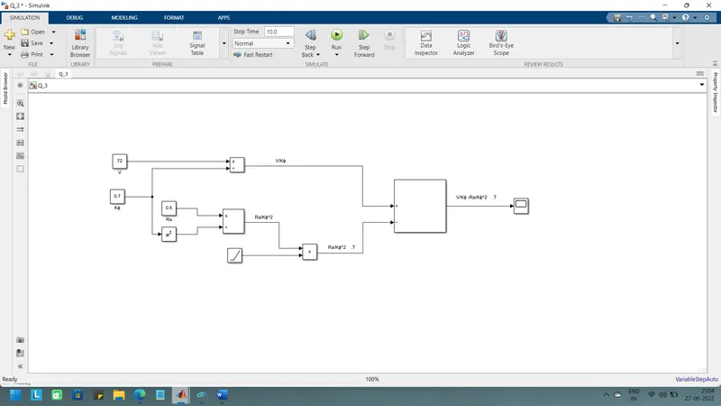
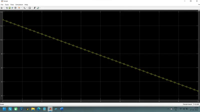
Then run the simulation the results are shown below
4.
The author wally ripple worked as an engineer at AeroVironment and helped to develop the EV1 for General Motors. Wally has also worked for the jet propulsion laboratory on electric vehicle battery research.
Then he explained the difference between the DC motor and induction motor and their uses in EV designing, and also discussed about their advantages and disadvantages
And he said about DC brushless motor and that they contain permanent magnets which generates DC magnetic field. And also mentioned about the current controlled device known as inverter. And he also mentioned that without this device brushless DC motors are useless
And now he started to explain about the induction motors. He mentioned that a 3-phase induction motor and brushless DC motors, both are virtually identical
He said that the induction motor has no magnets.
when a 3-phase induction motor is connected to utility type 3-phase power, torque is produced at the outset; the motor has the ability to start under load and mentioned that there is no need of inverter in this.
He also said that induction motors are directly compatible with conventional utility power is the main reason for their success. In contrast, a brushless DC motor produces no starting torque when directly connected to fixed frequency utility power. They really need the aid of an inverter whose “phase” is maintained in step with the angular position of the rotor
While he deciding that DC brushless or induction, he stated that Back in the 1990s all of the electric vehicles except one were powered by DC brushless drives. Today, all the hybrids are powered by DC brushless drives, with no exceptions. The only notable uses of induction drives have been the General Motors
And then he also included a point that both DC brushless and induction drives use motors having similar stators. Both drives use 3-phase modulating inverters. The only differences are the rotors and the inverter controls. And with digital controllers, the only control differences are with control code
And here if we see the author said that the major difference between two motors is that much less rotor heat is generated with the DC brushless drive. Rotor cooling is easier and peak point efficiency is generally higher for this drive. The DC brushless drive can also operate at unity power factor, whereas the best power factor for the induction drive is about 85 percent. This means that the peak point energy efficiency for a DC brushless drive will typically be a few percentage points higher than for an induction drive.
And then he explained about the cost of permanent magnets in DC motor and also it is difficult to handle, so in his view induction motors are cost advantage motors compare to PMDC motors.
And he also stated that the controlling of the induction motors is not so easy and also over temperature is one of the disadvantage.
And also, he said that the induction motor is more efficient while using in pure electric vehicles & brushless dc motor is more efficient for hybrid and plug-in hybrid vehicles.