Final Project: Electric Rickshaw modelling
Create a detailed MATLAB model of an electric rickshaw (three wheel passenger vehicle) as per details below:
Rear wheels driven by PM brushed type motor
Assume efficiency points of motor controller and motor
Make an excel sheet of all input and assumed data
Results: For any three standard driving cycles show energy consumption, temperature rise of motor and controller for 100 km constant speed driving at 45 kmph.
Block Diagram of Electric Rickshaw Drivetrain:
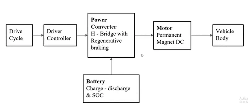
Drive train of electric rikshaw is shown below
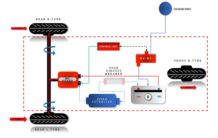
The drive train of E-rikshaw consist of
DC motor
Battery
Controller
Power converter
Transmission
Drive cycle source
DC motor: in this project I am taking PMDC motor
What is a Permanent Magnet DC Motor (PMDC Motor)?
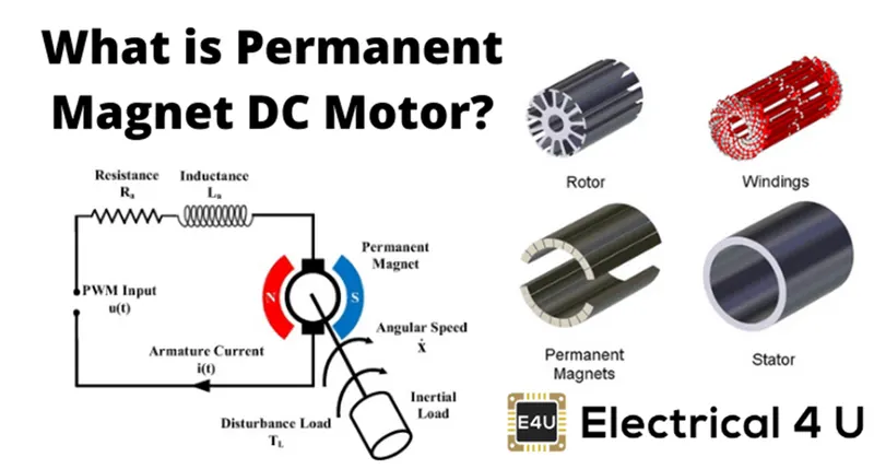
In a DC motor, an armature rotates inside a magnetic field. The basic working principle of a dc motor is based on the fact that whenever a current carrying conductor is placed inside a magnetic field, there will be mechanical force experienced by that conductor.
All kinds of DC motors work under this principle. Hence for constructing a dc motor, it is essential to establish a magnetic field. The magnetic field is established by using a magnet. You can use different types of magnets – it may be an electromagnet or it can be a permanent magnet.
A Permanent Magnet DC motor (PMDC motor) is a type of dc motor that uses a permanent magnet to create the magnetic field required for the operation of a DC motor.
Have you ever used a battery operated toy? The motor that drives these toys is nothing but a permanent magnet DC motor or PMDC motor. These types of motors are simple in construction.
They are commonly used as a starter motor in automobiles, windshield wipers, washers, blowers used in heaters and air conditioners, to raise and lower windows – and they are extensively used in toys.
As the magnetic field strength of a permanent magnet is fixed it cannot be controlled externally, field control of this type of DC motor cannot be possible.
Thus permanent magnet DC motor is used where there is no need to control the speed of the motor (which is usually done by controlling the magnetic field). Small fractional and sub-fractional KW motors are often constructed using a permanent magnet.
Construction of Permanent Magnet DC Motor or PMDC Motor
As it is indicated in name of permanent magnet DC motor, the field poles of this motor are essentially made of permanent magnet.
A PMDC motor mainly consists of two parts. A stator and an armature. Here the stator which is a steel cylinder. The magnets are mounted in the inner periphery of this cylinder.
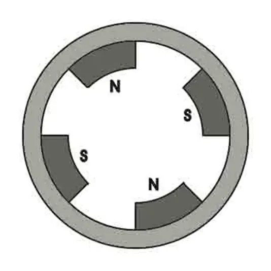
The permanent magnets are mounted in such a way that the N-pole and S-pole of each magnet are alternatively faced towards armature as shown in the figure below. That means, if N-pole of one magnet is faced towards armature then S-pole of very next magnet is faced towards armature.
In addition to holding the magnet on its inner periphery, the steel cylindrical stator also serves as low reluctance return path for the magnetic flux.
Although field coil is not required in permanent magnet DC motor still it is sometimes found that they are used along with permanent magnet.
This is because if permanent magnets lose their strength, these lost magnetic strengths can be compensated by field excitation through these field coils. Generally, rare earth hard magnetic materials are used in these permanent magnets.
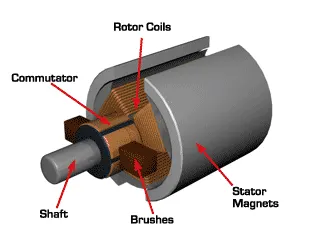
The rotor of a PMDC motor is similar to other DC motors. The rotor or armature of a permanent magnet DC motor also consists of a core, windings, and commutator. Armature core is made of a number of varnishes insulated, slotted circular lamination of steel sheets.
By fixing these circular steel sheets one by one, a cylindrical shaped slotted armature core is formed. The varnish insulated laminated steel sheets are used to reduce eddy current loss in armature of permanent magnet DC motor.
These slots on the outer periphery of the armature core are used for housing armature conductors in them. The armature conductors are connected in a suitable manner which gives rise to armature winding.
The end terminals of the winding are connected to the commutator segments placed on the motor shaft. Like other DC motors, carbon or graphite brushes are placed with spring pressure on the commutator segments to supply current to the armature.
Working Principle of Permanent Magnet DC Motor or PMDC Motor
As we said earlier the working principle of PMDC motor is just similar to the general working principle of dc motor. That is when a carrying conductor comes inside a magnetic field, a mechanical force will be experienced by the conductor and the direction of this force is governed by Fleming’s left-hand rule.
As in a permanent magnet DC motor, the armature is placed inside the magnetic field of a permanent magnet; the armature rotates in the direction of the generated force.
Here each conductor of the armature experiences the mechanical force F = B.I.L Newton where, B is the magnetic field strength in Tesla (weber / m2), I is the current in Ampere flowing through that conductor and L is the length of the conductor in meter comes under the magnetic field.
Each conductor of the armature experiences a force and the compilation of those forces produces a torque, which tends to rotate the armature.
Battery:
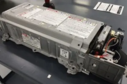
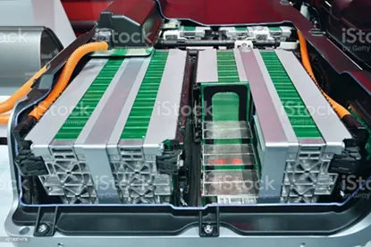
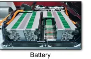
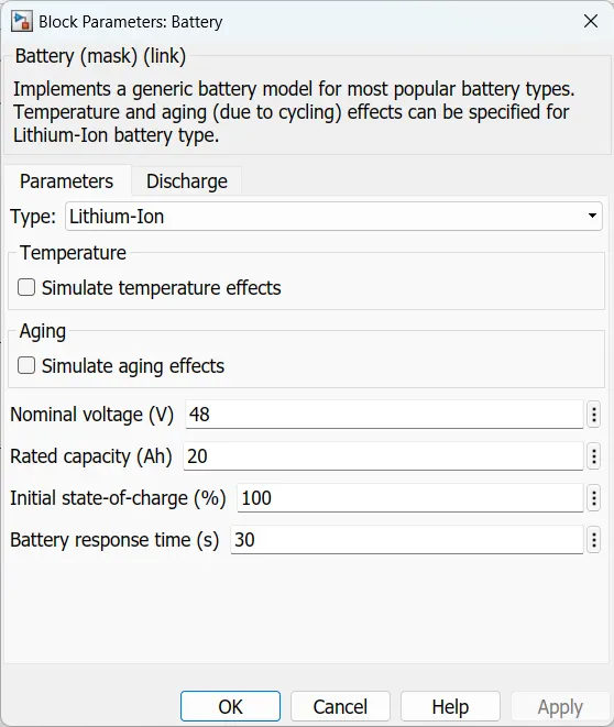
The function of the battery in an electric vehicle is as an electrical energy storage system in the form of direct-current electricity (DC). If it gets a signal from the controller, the battery will flow DC electrical energy to the inverter to then be used to drive the motor. The type of battery used is a rechargeable battery that is arranged in such a way as to form what is called a traction battery pack.
There are various types of electric car batteries. The most widely used is the type of lithium-ion batteries.
Controller:
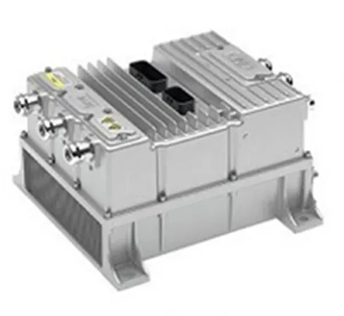
The main function of the controller is as a regulator of electrical energy from batteries and inverters that will be distributed to electric motors. While the controller itself gets the main input from the car pedal (which is set by the driver). This pedal setting will determine the frequency variation or voltage variation that will enter the motor, and at the same time determine the vehicle speed.
In brief, this unit manages the flow of electrical energy delivered by the traction battery, controlling the speed of the electric traction motor and the torque it produces. This component will determine how electric rikshaw work.
Power converter:
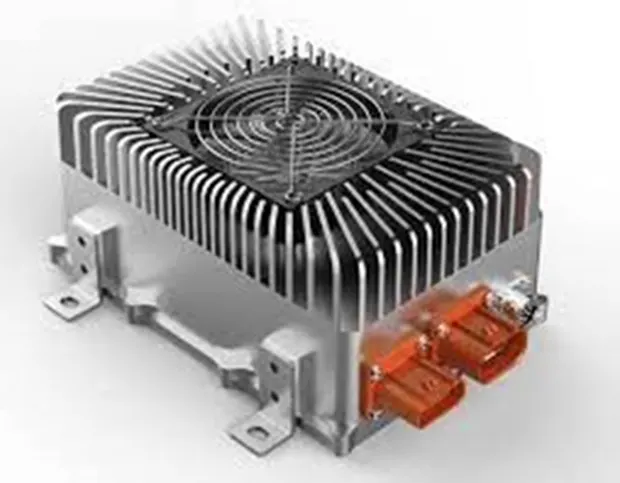
The different configurations of EV power supply show that at least one DC/DC converter is necessary to interface the FC, the Battery, or the Supercapacitors module to the DC-link.
In electrical engineering, a DC-to-DC converter is a category of power converters and it is an electric circuit that converts a source of direct current (DC) from one voltage level to another, by storing the input energy temporarily and then releasing that energy to the output at a different voltage. The storage may be in either magnetic field storage components (inductors, transformers) or electric field storage components (capacitors).
DC/DC converters can be designed to transfer power in only one direction, from the input to the output. However, almost all DC/DC converter topologies can be made bi-directional. A bi-directional converter can move power in either direction, which is useful in applications requiring regenerative braking.
The amount of power flow between the input and the output can be controlled by adjusting the duty cycle (ratio of the on/off time of the switch). Usually, this is done to control the output voltage, the input current, and the output current, or to maintain constant power. Transformer-based converters may provide isolation between the input and the output.
Transmission:
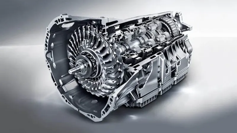
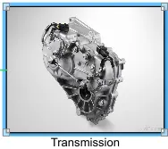
It is used to transfer the mechanical power from the electric motor to the wheels, through a gearbox. The advantage of electric cars is that they do not require multi-speed transmissions. The transmission efficiency should be high to avoid power loss.
Drive cycle source:
The Drive Cycle Source block generates a standard or user-specified longitudinal drive cycle. The block output is the specified vehicle longitudinal speed, which you can use to:
Predict the engine torque and fuel consumption that a vehicle requires to achieve desired speed and acceleration for a given gear shift reference.
Produce realistic velocity and shift references for closed-loop acceleration and braking commands for vehicle control and plant models.
Study, tune, and optimize vehicle control, system performance, and system robustness over multiple drive cycles.
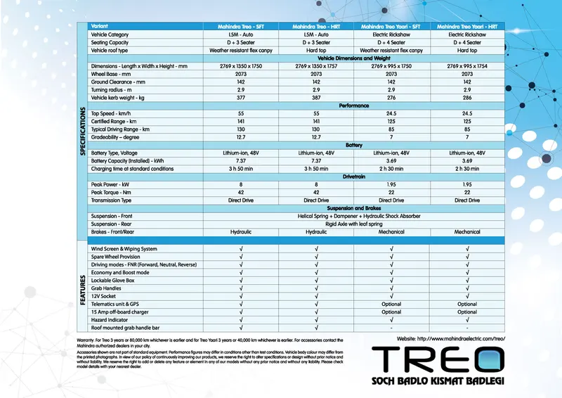
I am taking a data sheet for desining the E-Rikshaw as shown below
The simulation model is shown below
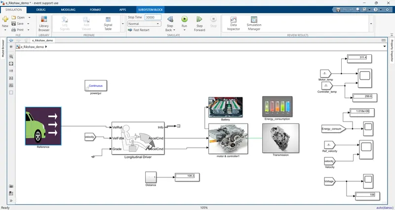
Blocks used in the simulation are shown below
Drive cycle source
Signal builder
Constant
Multiport switch
Longitudinal driver
Terminator
Simulink-PS converter
PS-Simulink converter
Powergui
Connecting port
Controlled voltage source
Controlled PWM voltage
H-bridge
Solver configuration
Electrical Reference
Current Sensor
Temperature Sensor
Thermal Reference
Goto
From
Voltage sensor
Outport
Inport
PMDC Motor
Mechanical rotational reference
Vehicle body
Tire
Simple gear
Scope
Model explanation:
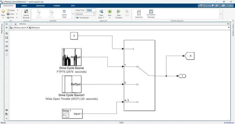
First i am giving the reference velocity to the model the subsystem is shown below
The block parameters are shown below
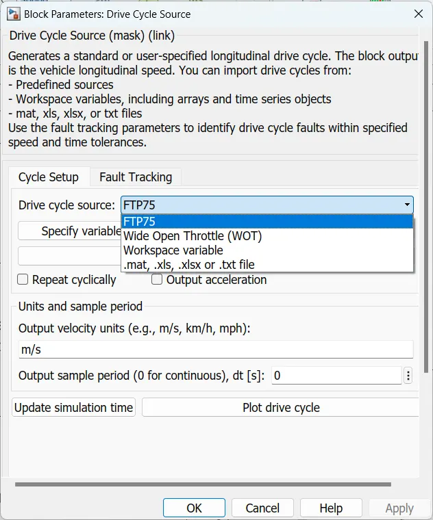
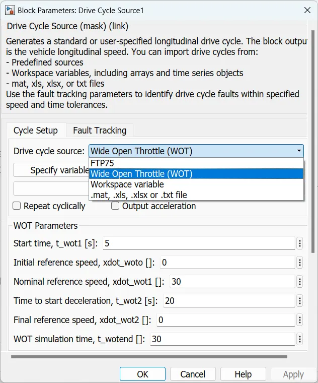
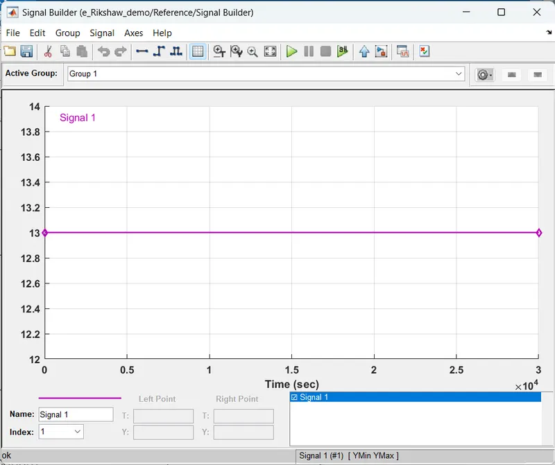
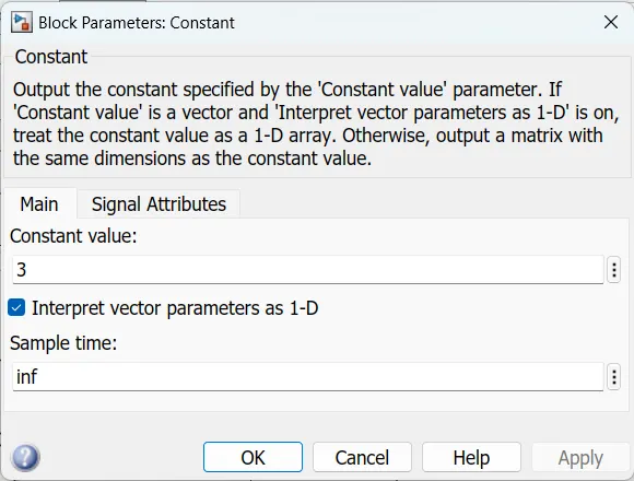
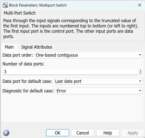
In this project i am taking two standard & one normal drive cycles as reference velocity that are FTP75, WOT and another one is i am creating a drive cycle for 100 km constant speed driving at 45 kmph so i am converting 45kmph to m/s because of longitudinal driver block can take m/sec only then after conversion of kmph to m/s velocity is 13m/s and the run time is 30000sec to reach the 100km distance the drive cycle is created in signal builder as shown above.and the drive cycle sources are connected to multiport switch for selecting the drive cycle.
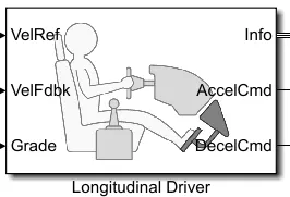
longitudinal Driver block
the block parameters are shown below
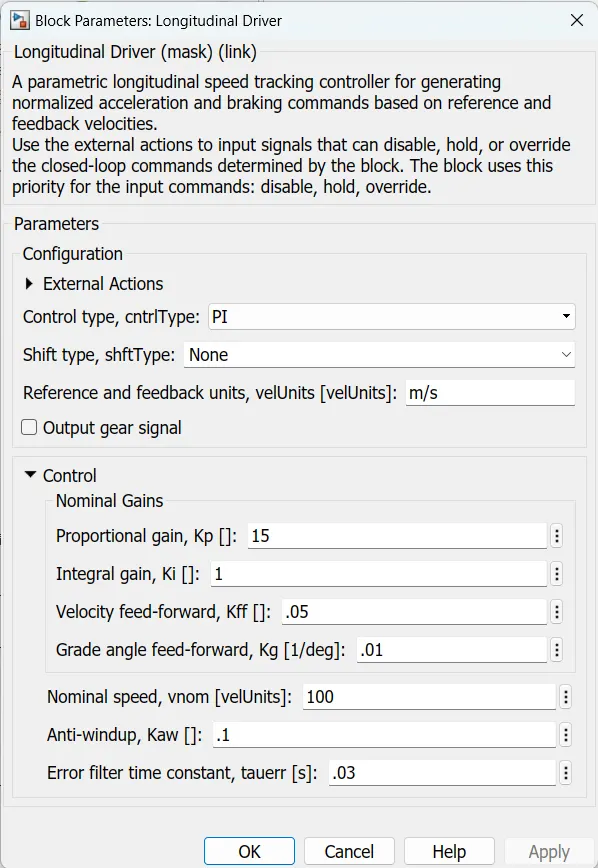
In this block consist of three inputs and three outputs inputs are vel ref,vel fdbk & grade.outputs are accelcmd,decelcmd & info. the ref_velocity output is connected to velref port and the actual velocity is connected to velfdbk port and the grade is considerd as zero in this case and the accelcmd port is connected to motor controller controlled voltage source and the decelcmd is connected to another controlled voltage source(brake).
Motor & controller subsystem:
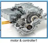
The inside the subsytem is shown below
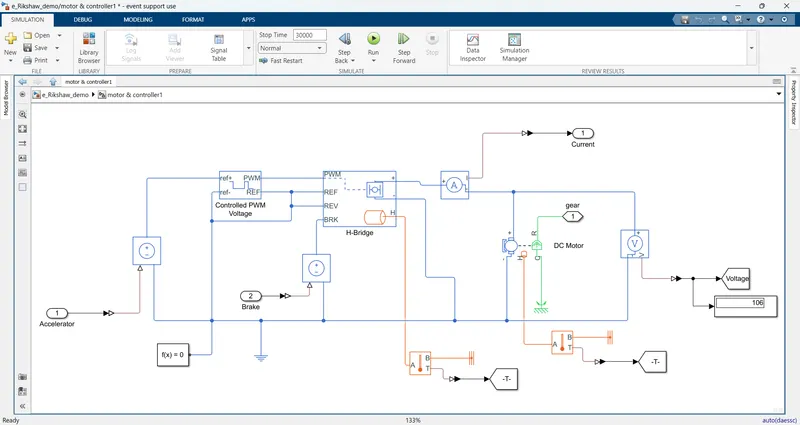
Block parameters are shown below
H-bridge:
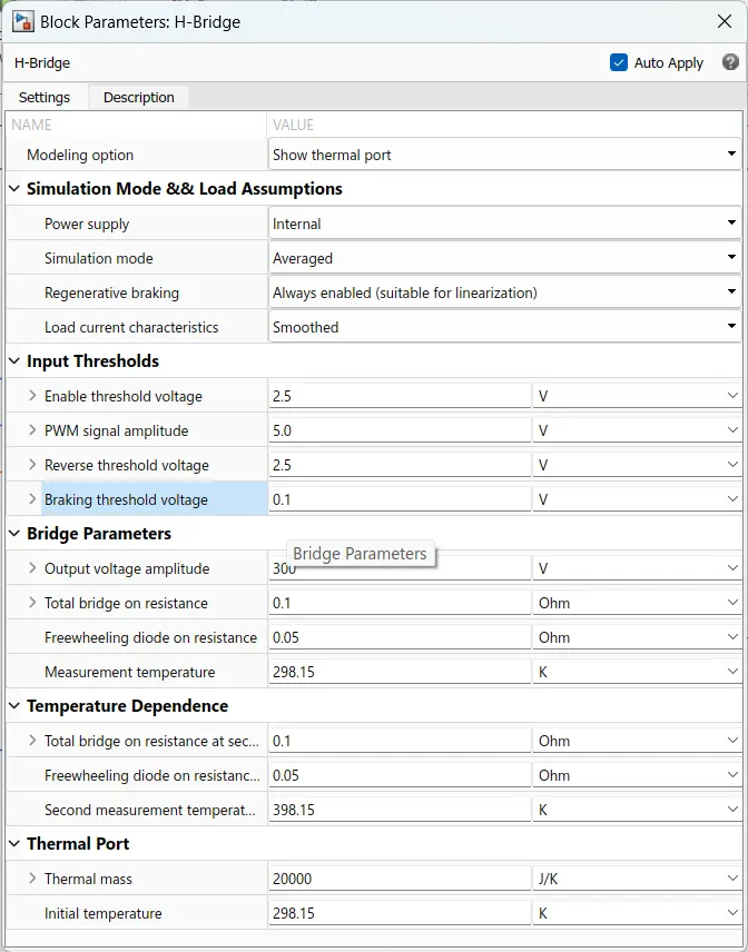
The H-Bridge block represents an H-bridge motor driver. The block has the following two Simulation mode options:
- PWM — The H-Bridge block output is a controlled voltage that depends on the input signal at the PWM port. If the input signal has a value greater than the Enable threshold voltage parameter value, the H-Bridge block output is on and has a value equal to the value of the Output voltage amplitude parameter. If it has a value less than the Enable threshold voltage parameter value, the block maintains the load circuit using one of the following three Freewheeling mode options:
- Via one semiconductor switch and one freewheeling diode
- Via two freewheeling diodes
- Via two semiconductor switches and one freewheeling diode
The first and third options are sometimes referred to as synchronous operation.
The signal at the REV port determines the polarity of the output. If the value of the signal at the REV port is less than the value of the Reverse threshold voltage parameter, the output has positive polarity; otherwise, it has negative polarity.
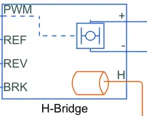
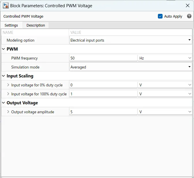
In this block PWM port is connected to controlled pwm voltage then REF & REV ports are connected to electrical referance & BRK port is connected to controlled voltage source and input of the controlled voltage source is connected to decelration comand port of the longitudinal driver block then positive port is connected to motor through current sensor & negative port is connected to electrical ref. and i am enabling the thermal port for sensing the temperature so thermal port is connected to temperature sensor
Controlled PWM voltage source:
The Controlled PWM Voltage block represents a pulse-width modulated (PWM) voltage source. You can model electrical or physical signal input ports by setting the Modeling option parameter to either: Electrical input ports — The block calculates the duty cycle based on the reference voltage across its ref+ and ref- ports.
The value of the Output voltage amplitude parameter determines amplitude of the output voltage.
At time zero, the pulse is initialized as high, unless the Pulse delay time parameter is greater than zero, or the demanded duty cycle is zero.
You can use parameters Pulse delay time and Pulse width offset to add a small turn-on delay and a small turn-off advance. This can be useful when fine-tuning switching times so as to minimize switching losses.
In PWM mode, the block has two options for the type of switching event when moving between output high and output low states:
- Asynchronous – Best for variable-step solvers — Asynchronous events are better suited to variable step solvers, because they require fewer simulation steps for the same level of accuracy. In asynchronous mode the PWM switching events generate zero crossings, and therefore switching times are always determined accurately, regardless of the simulation maximum step size.
- Discrete—time – Best for fixed-step solvers — Discrete-time events are better suited to fixed-step operation, because then the switching events are always synchronized with the simulation step. Using an asynchronous implementation with fixed-step solvers may sometimes result in events being up to one simulation step late.
- If you use a fixed-step or local solver and the discrete-time switching event type, the following restrictions apply to the Sample timeparameter value:
- The sample time must be a multiple of the simulation step size.
- The sample time must be small compared to the PWM period, to ensure sufficient resolution.
ref+ port is connected to positive terminal of the controlled voltage source, ref- & REF ports are connected to electrical referance.
DC motor:
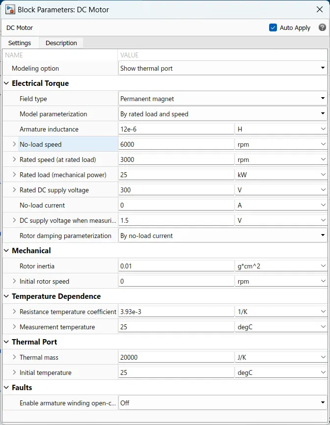
This block represents the electrical and torque characteristics of a DC motor.
The block assumes that no electromagnetic energy is lost, and hence the back-emf and torque constants have the same numerical value when in SI units. Motor parameters can either be specified directly, or derived from no-load speed and stall torque. If no information is available on armature inductance, this parameter can be set to some small non-zero value.
When a positive current flows from the electrical + to - ports, a positive torque acts from the mechanical C to R ports. Motor torque direction can be changed by altering the sign of the back-emf or torque constants.
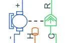
The positive and negative terminals of the dc motor is connected to the positive and negative terminal of the H-bridge and the C terminal of the motor is connected to the mechanical rotational reference and the R port is connected to the Shaft of the transmission system. and thermal port is enabled and is connected to temperature sensor for sensing the temperature of the motor.
Controlled voltage source:
The block represents an ideal voltage source that is powerful enough to maintain the specified voltage at its output regardless of the current passing through it. The output voltage is V = Vs, where Vs is the numerical value presented at the physical signal port.The block has one physical signal input port and two electrical conserving ports associated with its electrical terminals.
Solver configuration:
Each physical network represented by a connected Simscape™ block diagram requires solver settings information for simulation. The Solver Configuration block specifies the solver parameters that your model needs before you can begin simulation.
Each topologically distinct Simscape block diagram requires exactly one Solver Configuration block to be connected to it.
It is connected to ground of the system.
mechanical rotational reference :
The Mechanical Rotational Reference block represents a reference point, or frame, for all mechanical rotational ports. All rotational ports that are rigidly clamped to the frame (ground) must be connected to a Mechanical Rotational Reference block.
as we have a dc motor and it is also a mechanicalpart so the C port of the motor is connected to the mechanical rotational reference part. below image represents the basic block of the mechanical rotational reference.
Transmission:
Inside the transmission is shown below
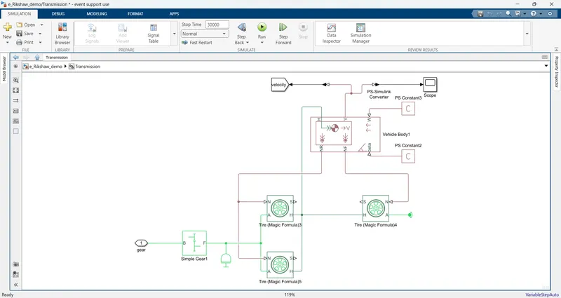
Vehicle body :
The Vehicle Body block represents a two-axle vehicle body in longitudinal motion. The vehicle can have the same or a different number of wheels on each axle. For example, two wheels on the front axle and one wheel on the rear axle. The vehicle wheels are assumed identical in size. The vehicle can also have a center of gravity (CG) that is at or below the plane of travel.
The block accounts for body mass, aerodynamic drag, road incline, and weight distribution between axles due to acceleration and road profile. Optionally include pitch and suspension dynamics. The vehicle does not move vertically relative to the ground.
The block has an option to include an externally-defined mass and an externally-defined inertia. The mass, inertia, and center of gravity of the vehicle body can vary over the course of simulation in response to system changes.
he vehicle axles are parallel and form a plane. The longitudinal, x, direction lies in this plane and perpendicular to the axles. If the vehicle is traveling on an incline slope, β, the normal, z, direction is not parallel to gravity but is always perpendicular to the axle-longitudinal plane. below picture represents the basic block of the vehicle body
The vehicle body is having the following ports:
NR- It is a rear axle force port.
NF- It is a front axle force port.
Beta – This is a road incline angle port.
H – This port is connected to the horizontal motion of the vehicle’s body.
V – it is a vehicle longitudinal velocity port.
W – is the Headwind speed port.
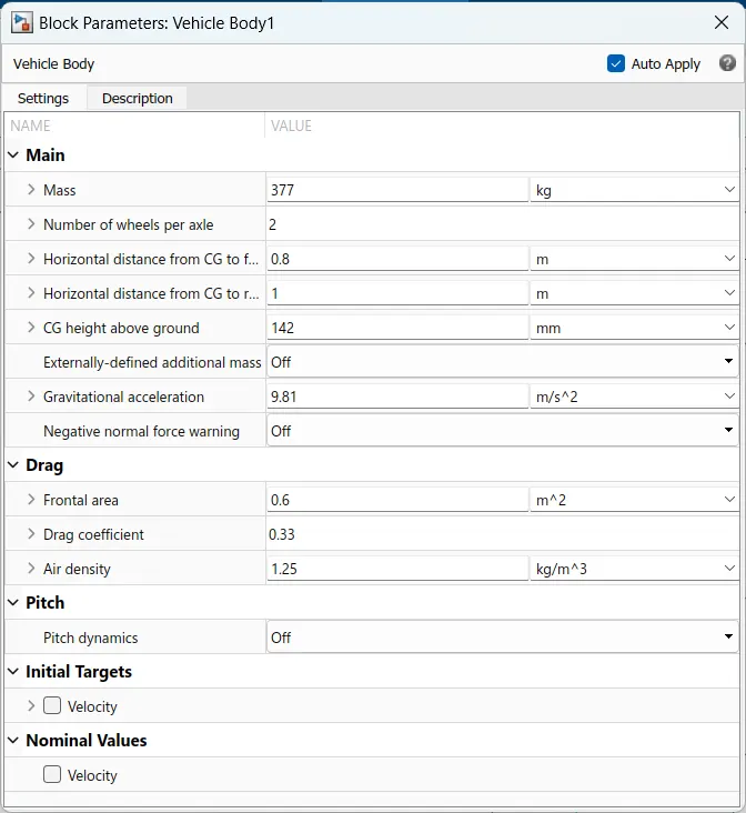
the parameters are shown below
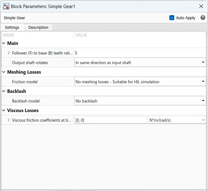
simple gear :
Represents a fixed-ratio gear or gear box. No inertia or compliance is modeled in this block. You can optionally include gear meshing and viscous bearing losses.
Connections B (base) and F (follower) are mechanical rotational conserving ports. Specify the relation between base and follower rotation directions with the Output shaft rotates parameter. Optionally include thermal effects and expose thermal conserving port H by setting Friction model to a temperature-dependent setting.
You choose whether the follower axis rotates in the same or opposite direction as the base axis. If they rotate in the same direction, the angular velocity of the follower, ωF, and the angular velocity of the base, ωB, have the same sign. If they rotate in opposite directions, ωF and ωB have opposite signs. You can easily add and remove backlash, faults, and thermal effects.
the below image represents the basic block of the simple gear.
Tire (magic formula) :
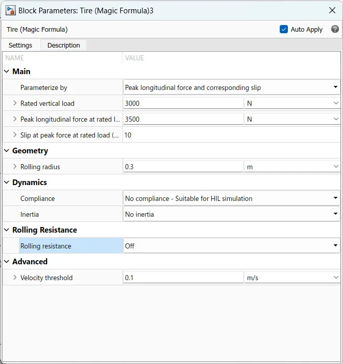
The Tire (Magic Formula) block models a tire with longitudinal behavior given by the Magic Formula [1], an empirical equation based on four fitting coefficients. The block can model tire dynamics under constant or variable pavement conditions.
The longitudinal direction of the tire is the same as its direction of motion as it rolls on pavement. This block is a structural component based on the tire road interaction (magic formula) block.
To increase the fidelity of the tire model, you can specify properties such as tire compliance, inertia, and rolling resistance. However, these properties increase the complexity of the tire model and can slow down simulation. Consider ignoring tire compliance and inertia if simulating the model in real time or if preparing the model for hardware-in-the-loop (HIL) simulation. below image represents the tire basic block.
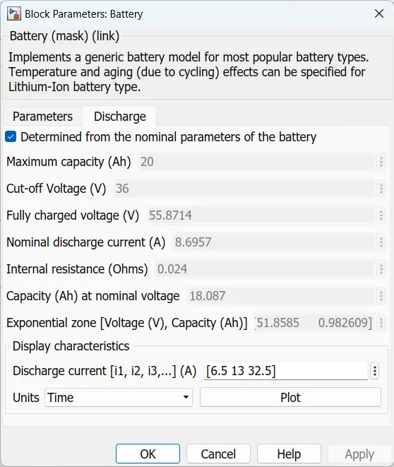
Battery:
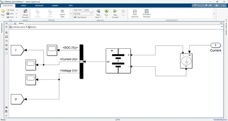
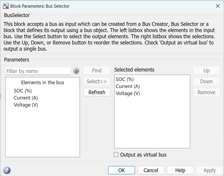
Inside the battery subsystem is shown below
Energy consumption:
Inside the subsystem is shown below
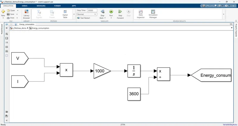
In this model i am calculating the energy consumption by using the voltage and current of the battery .
Distance:
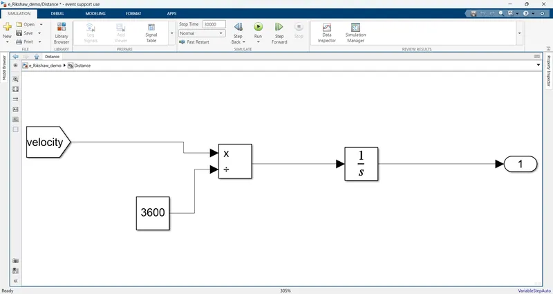
For the distance calculation, we are taking the velocity from the transmission subsystem and dividing it by 3600 the velocity is converted into kmph and then integrated with an integrator the distance in km can be observed in the display block.
Results:
Test-1
For the model i am using FTP drive cycle,WOT drive cycle & i am created a drive cycle for speed driving at 45 kmph by using signal builder. first i am running the FTP75 Drive cycle the results are shown below
The motor and controller temperature are shown below
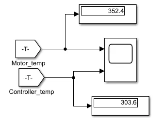
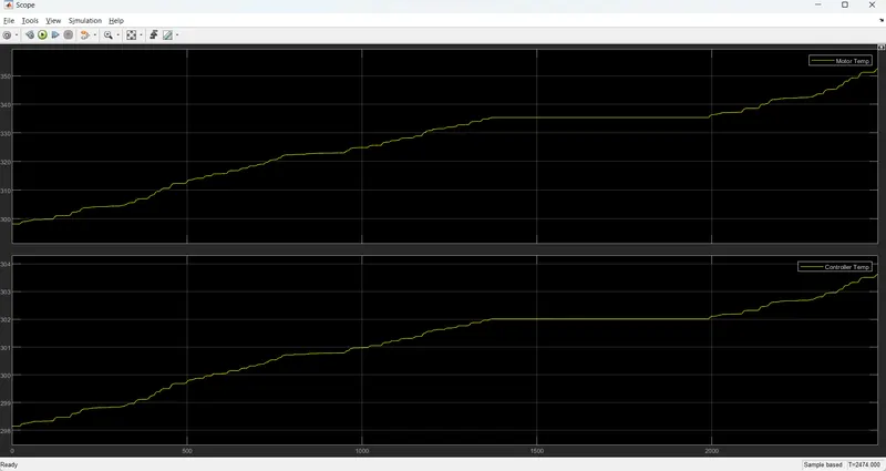
the motor temp and controller temp are shown above plot by using temperature sensor and the motor temp are raised to 352k & controller temp is raised to 304k
Ref velocity and actual velocity are shown below
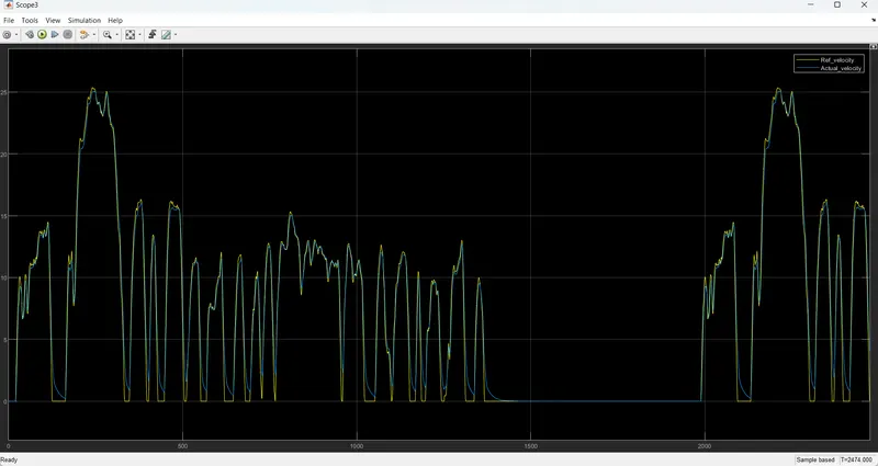
In the above plot, we can observe the reference velocity in the yellow line and the actual velocity in the blue line.
the actual velocity is tracking the reference velocity with small variations.
Energy consumption kwh:
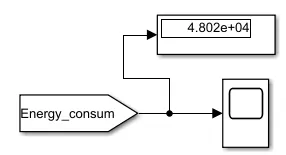
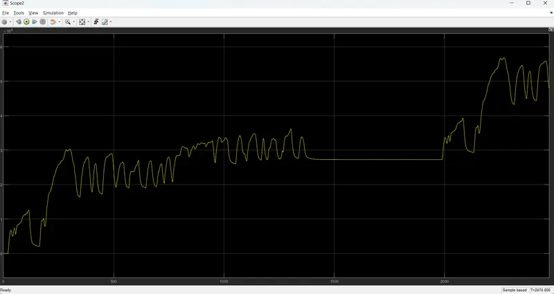
the energy consumed is 4.802e+04 kwh and the above plot is energy consumption of the model.
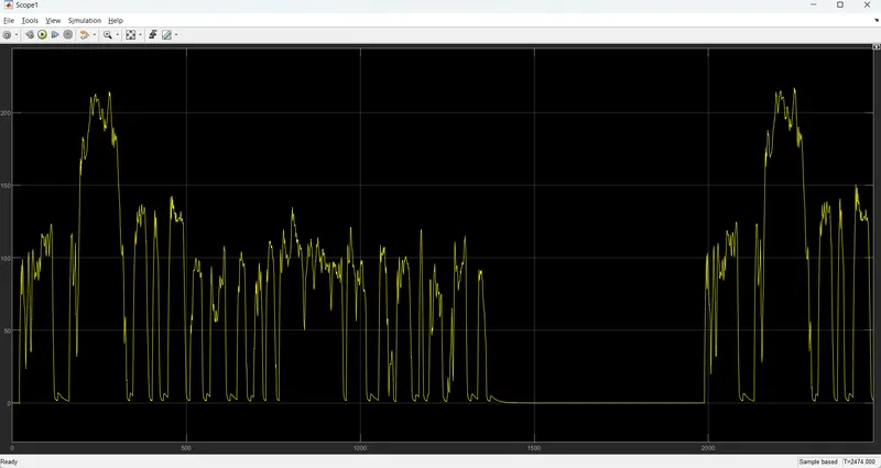
The motor voltage is shown below
Distance:
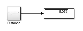
the vehicle with FTP75 drive cycle input traveled a 5.076km distance.
Test-2:
I am running the model by using WOT drive cycle
The motor and controller temperature are shown below
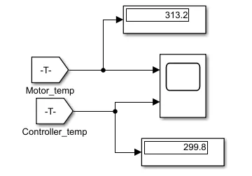
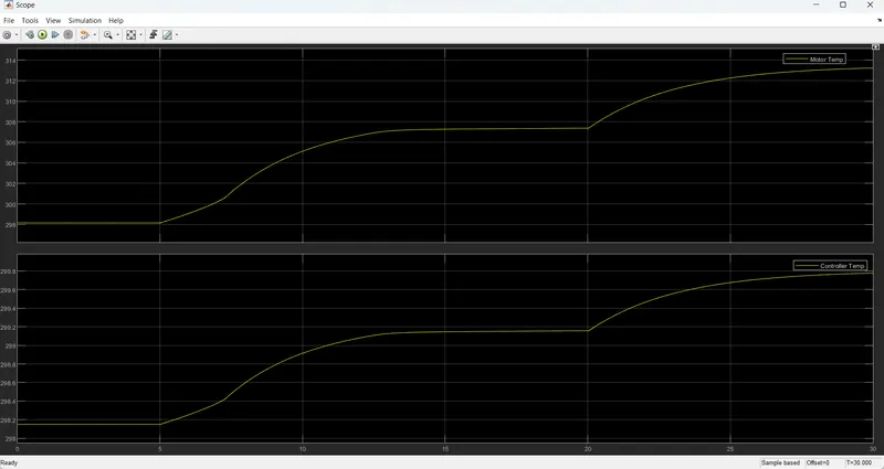
the motor temp and controller temp are shown above plot by using temperature sensor and the motor temp are raised to 313k & controller temp is raised to 299.8k
Ref velocity and actual velocity are shown below
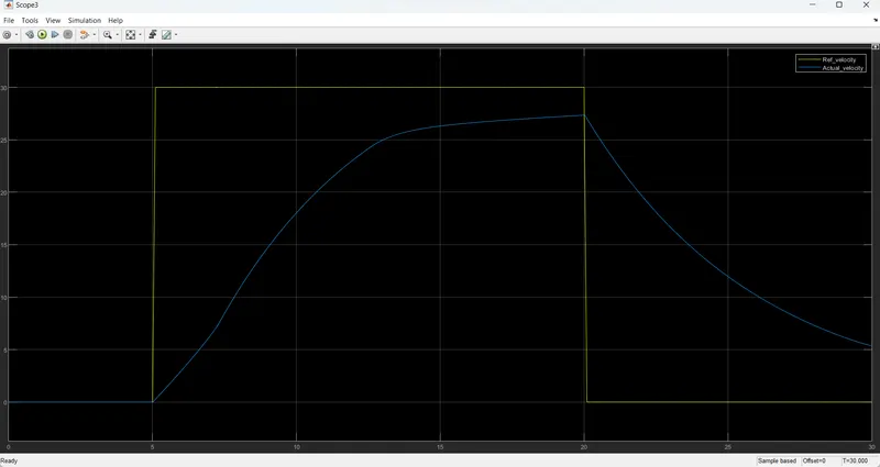
In the above plot, we can observe the reference velocity in the yellow line and the actual velocity in the blue line.
the actual velocity is tracking the reference velocity with small variations.
Energy consumption kwh:
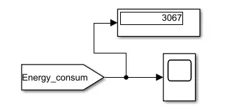
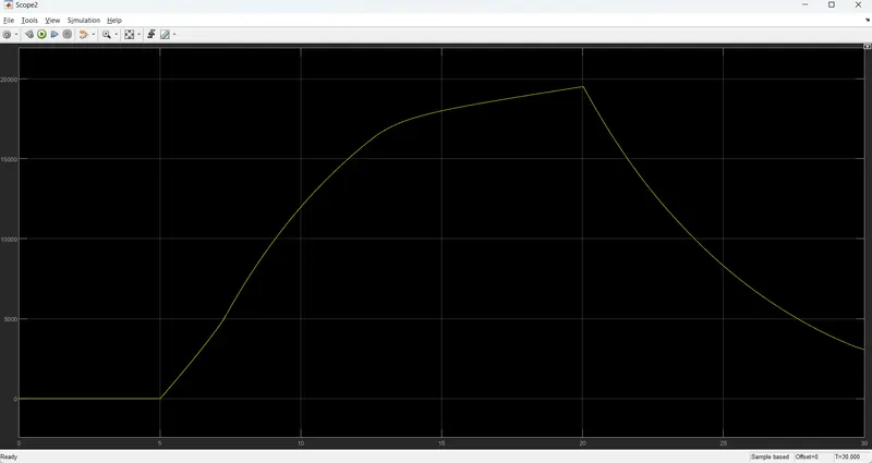
the energy consumed is 3067 kwh and the above plot is energy consumption of the model.
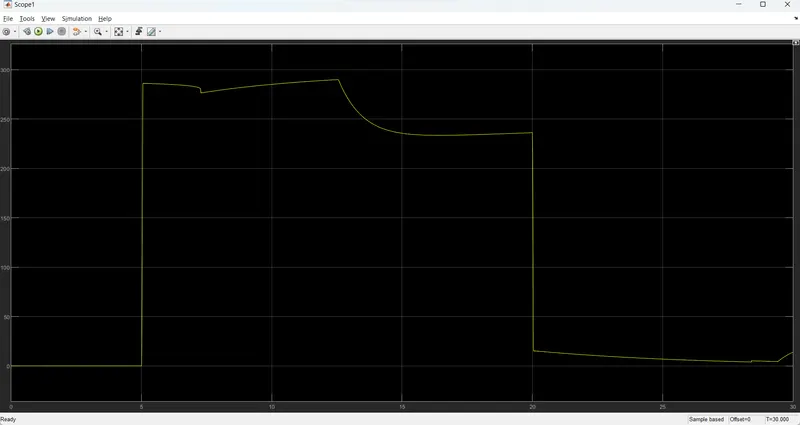
The motor voltage is shown below
Distance:
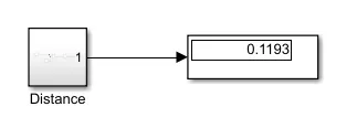
The vehicle with WOT drive cycle input traveled a 0.1193km distance.
Test-3:
For this test drive cycle input is taken in the signal builder:
Signal Builder:

In this model i am taking 45kmph as input so the longitudinal driver block can takes m/s only so i am converting the kmph to m/s 45kmph=13m/sec nearly. for reaching the 100km distance i am running the 30000sec.
The motor and controller temperature are shown below
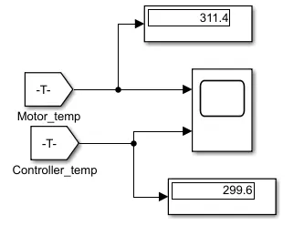
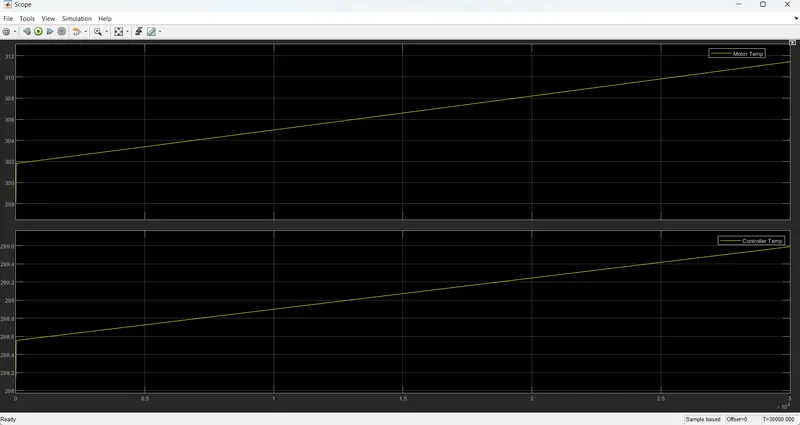
the motor temp and controller temp are shown above plot by using temperature sensor and the motor temp are raised to 311k & controller temp is raised to 299.6k
Ref velocity and actual velocity are shown below
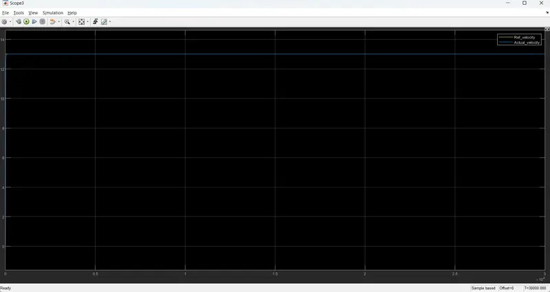
In the above plot, we can observe the reference velocity in the yellow line and the actual velocity in the blue line.
the actual velocity is tracking the reference velocity.
Energy consumption kwh:
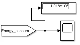
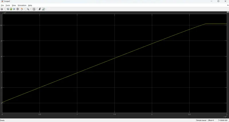
The energy consumed is 1.018e+06 kwh and the above plot is energy consumption of the model.
The motor voltage is shown below
Distance:
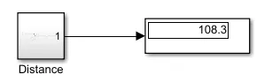
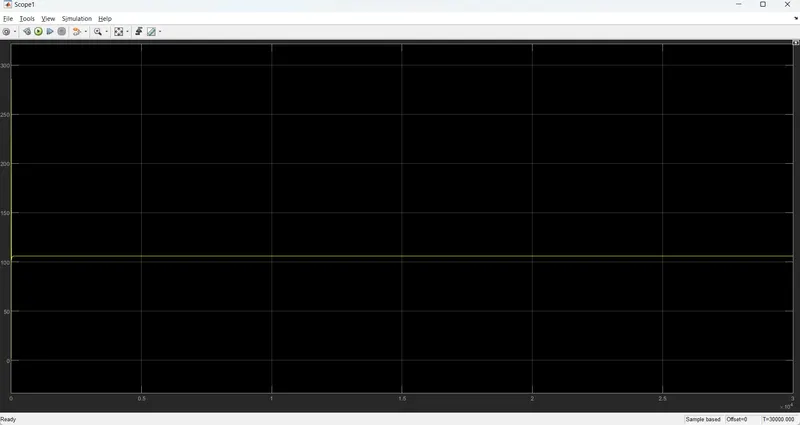
When the simulation runs for 30000 seconds with the 45kmph the distance traveled is 108.3km.