Project-1: Modelling an electric Car with Li-ion battery
Aim
* To create a simulink model of an Electric Vehicle by using battery,drive cycle,motor,h-bridge & vehicle body and run the simulation then checking the speed of motor and voltage, current & soc of battery.Then performance of vechicle also checked with FTP drive cycle
Electric vehicle
An electric vehicle (EV) is one that operates on an electric motor, instead of an internal-combustion engine that generates power by burning a mix of fuel and gases. Therefore, such as vehicle is seen as a possible replacement for current-generation automobile, in order to address the issue of rising pollution, global warming, depleting natural resources, etc. Though the concept of electric vehicles has been around for a long time, it has drawn a considerable amount of interest in the past decade amid a rising carbon footprint and other environmental impacts of fuel-based vehicles
Electric vehicles have low running costs as they have less moving parts for maintaining and also very environmentally friendly as they use little or no fossil fuels (petrol or diesel). While some EVs used lead acid or nickel metal hydride batteries, the standard for modern battery electric vehicles is now considered to be lithium ion batteries as they have a greater longevity and are excellent at retaining energy, with a self discharge rate of just 5% per month. Despite this improved efficiency, there are still challenges with these batteries as they can experience thermal runaway, which have, for example, caused fires or explosions in the Tesla model S, although efforts have been made to improve the safety of these batteries.
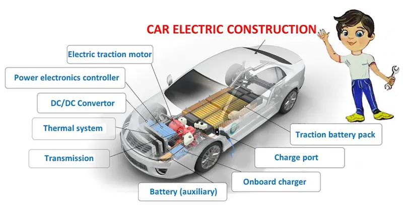
ELECTRIC CAR CONSIST OF:
- Battery
- Charge port;
- DC/DC Convertor;
- Electric traction motor;
- Onboard charger;
- Power electronics controller;
- Thermal system;
- Traction battery pack;
- Transmission
Traction Battery Pack (A)
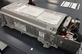
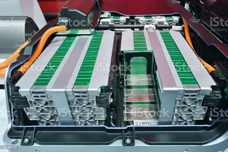
The function of the battery in an electric car is as an electrical energy storage system in the form of direct-current electricity (DC). If it gets a signal from the controller, the battery will flow DC electrical energy to the inverter to then be used to drive the motor. The type of battery used is a rechargeable battery that is arranged in such a way as to form what is called a traction battery pack.
There are various types of electric car batteries. The most widely used is the type of lithium-ion batteries.
Power Inverter
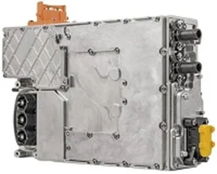
The inverter functions to change the direct current (DC) on the battery into an alternating current (AC) and then this alternating current is used by an electric motor. In addition, the inverter on an electric car also has a function to change the AC current when regenerative braking to DC current and then used to recharge the battery. The type of inverter used in some electric car models is the bi-directional inverter category.
Controller
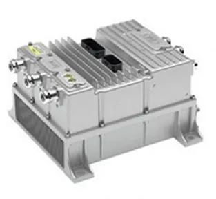
The main function of the controller is as a regulator of electrical energy from batteries and inverters that will be distributed to electric motors. While the controller itself gets the main input from the car pedal (which is set by the driver). This pedal setting will determine the frequency variation or voltage variation that will enter the motor, and at the same time determine the car’s speed.
In brief, this unit manages the flow of electrical energy delivered by the traction battery, controlling the speed of the electric traction motor and the torque it produces. This component will determine how electric car work.
Electric traction motor
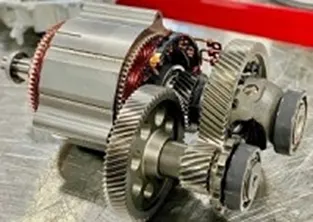
Because the controller provides electrical power from the traction battery, the electric traction motors will work turning the transmission and wheels. Some hybrid electric cars use a type of generator-motor that performs the functions of propulsion and regeneration. In general, the type of electric motor used is the BLDC (brushless DC) motor
Charger (E) is a battery charging device. Chargers get electricity from outside sources, such as the utility grid or solar power plants. AC electricity is converted into DC electricity and then stored in the battery. There are 2 types of electric car chargers:
- On-board charger: the charger is located and installed in the car
- Off-board charger: the charger is not located or not installed in the car.
- Transmission (F):The transmission transfers mechanical power from the electric traction motor to drive the wheels.
- DC/DC Converter (G):This one of electric car parts that to converts higher-voltage DC power from the traction battery pack to the lower-voltage DC power needed to run vehicle accessories and recharge the auxiliary battery.
- Battery (H):In an electric drive vehicle, the auxiliary battery provides electricity to power vehicle accessories.
- Thermal System – Cooling (I):This system maintains a proper operating temperature range of the engine, electric motor, power electronics, and other components.
- Charge Port (J):The charge port allows the vehicle to connect to an external power supply in order to charge the traction battery pack.
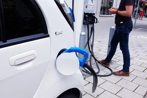
Different types of electric cars changed and are developed continuously giving users and potential users choices. Today the world is increasingly familiar with the terms BEV, HEV, PHEV and FCEV. How does an electric car work? How an electric vehicle works is depend on the type. This article will briefly discuss the types and working principles of electric cars or vehicles marketed in the World and Indonesia today.
An electric car is a vehicle that is fully or partially propelled by electric motors, using energy stored in rechargeable batteries. The first practical electric cars were produced in the 1880s. Electric cars were popular in the late 19th century and early 20th century. Innovation and advanced development in internal combustion engines (ICE) and mass production of cheaper gasoline vehicles has led to a decline in the use of electric vehicles.
When pedal of the car is pressed, then:
- Controller takes and regulates electrical energy from batteries and inverters
- With the controller set, the inverter then sends a certain amount of electrical energy to the motor (according to the depth of pressure on the pedal)
- Electric motor converts electrical energy into mechanical energy (rotation)
- Rotation of the motor rotor rotates the transmission so the wheels turn and then the car moves.
Note: The working principle above is for battery electric vehicle (BEV) type.
Types of Electric Cars
There are 4 (four) types of electric cars, with the following outline:
- Battery Electric Vehicle (BEV)
- Hybrid Electric Vehicle (HEV)
- Plug-in Hybrid Electric Vehicle (PHEV)
Battery Electric Vehicle (BEV)
A Battery Electric Vehicle (BEV), also called All-Electric Vehicle (AEV), runs entirely on a battery and electric drive train. This types of electric cars do not have an ICE. Electricity is stored in a large battery pack that is charged by plugging into the electricity grid. The battery pack, in turn, provides power to one or more electric motors to run the electric car.
Architecture and main components of BEV
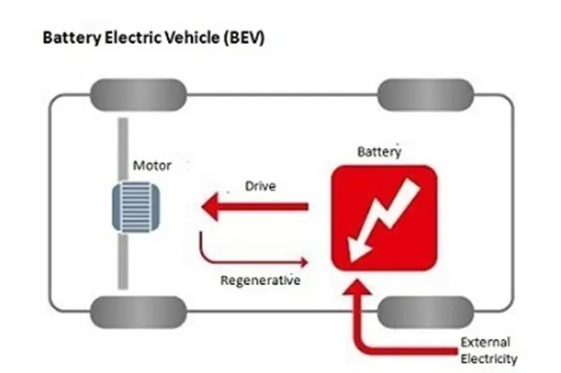
Components of BEV
- Electric motor
- Inverter
- Battery
- Control Module
- Drive train
Working principle of BEV
- Power is converted from the DC battery to AC for the electric motor
- The accelerator pedal sends a signal to the controller which adjusts the vehicle’s speed by changing the frequency of the AC power from the inverter to the motor
- The motor connects and turns the wheels through a cog
- When the brakes are pressed or the electric car is decelerating, the motor becomes an alternator and produces power, which is sent back to the battery
Examples of BEV
Volkswagen e-Golf, Tesla Model 3, BMW i3, Chevy Bolt, Chevy Spark, Nissan LEAF, Ford Focus Electric, Hyundai Ioniq, Karma Revera, Kia Soul, Mitsubishi i-MiEV, Tesla X, Toyota Rav4.
Hybrid Electric Vehicle (HEV)
This type of hybrid cars is often called as standard hybrid or paralel hybrid. HEV has both an ICE and an electric motor. In this types of electric cars, internal combustion engine gets energy from fuel (gasoline and others type of fuels), while the motor gets electricity from batteries. The gasoline engine and electric motor simultaneously rotate the transmission, which drives the wheels.
The difference between HEV compared to BEV and PHEV is where the batteries in HEV can only charged by the ICE, the motion of the wheels or a combination of both. There is no charging port, so that the battery cannot be recharged from outside of the system, for example from the electricity grid.
Architecture and main components of HEV
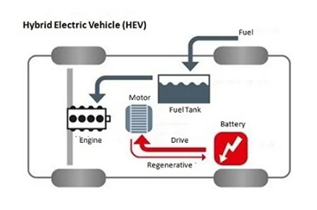
Components of HEV
- Engine
- Electric motor
- Battery pack with controller & inverter
- Fuel tank
- Control module
Working principle of HEV
- Has a fuel tank that supplies gas to the engine like a regular car
- It also has a set of batteries that run an electric motor
- Both the engine and electric motor can turn the transmission at the same time.
Examples of HEV
Honda Civic Hybrid, Toyota Prius Hybrid, Honda Civic Hybrid, Toyota Camry Hybrid.
Plug-in Hybrid Electric Vehicle (PHEV)
PHEV is a type of hybrid vehicle that both an ICE and a motor, often called as series hybrid. This type of electric cars offers a choice of fuels. This type of electric cars is powered by a conventional fuel (such as gasoline) or an alternative fuel (such bio-diesel) and by a rechargeable battery pack. The battery can be charged up with electricity by plugging into an electrical outlet or electrical vehicle charging station (EVCS).
PHEV typically can run in at least two modes:
- All-electric Mode, in which the motor and battery provide all the car’s energy
- Hybrid Mode, in which both electricity and gasoline are employed.
Some PHEVs can travel more than 70 miles on electricity alone
Architecture and main components of PHEV
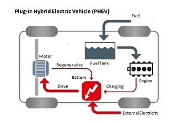
Components of PHEV
- Electric motor
- Engine
- Inverter
- Battery
- Fuel tank
- Control module
- Battery Charger (if onboard model)
Working principle of PHEV
PHEVs typically start up in all-electric mode and operate on electricity until their battery pack is depleted. Some models shift to hybrid mode when they reach highway cruising speed, generally above 60 or 70 miles per hour. Once the battery is empty, the engine takes over and the vehicle operates as a conventional, non-plug-in hybrid.
In addition to plugging into an outside electric power source, PHEV batteries can be charged by an internal combustion engine or regenerative braking. During braking, the electric motor acts as a generator, using the energy to charge the battery. The electric motor supplements the engine’s power; as a result, smaller engines can be used, increasing the car’s fuel efficiency without compromising performance.
Examples of PHEV
Porsche Cayenne S E-Hybrid , Chevy Volt, Chrysler Pacifica, Ford C-Max Energi, Ford Fusion Energi, Mercedes C350e, Mercedes S550e, Mercedes GLE550e, Mini Cooper SE Countryman, Audi A3 E-Tron, BMW 330e, BMW i8, BMW X5 xdrive40e, Fiat 500e, Hyundai Sonata, Kia Optima, Porsche Panamera S E-hybrid, Volvo XC90 T8.
Block diagram of EV
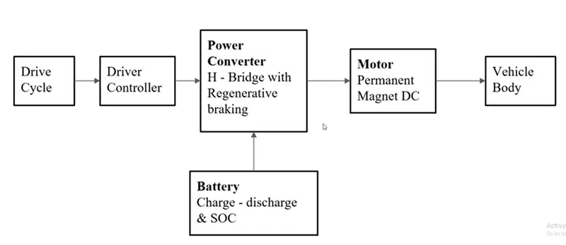
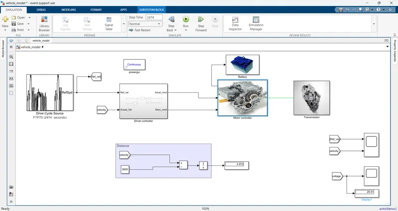
Drive cycle is used for input of the driver controller The driver controller controls the Acceleration and Braking of the power converter. The power converter H- Bridge is having a regenerative braking system. The DC motor is driven by the H-Bridge power converter. DC motor is connected to the vehicle body block. This block consists of vehicle transmission components like gear, wheels, and vehicle body. Finally, the battery is connected to the power converter block. This block consists of battery parameters charge, discharge, and SOC. The driver controller block has velocity feedback from the vehicle body to control the power converter.
Model is developed by using drive cycle,PID controller,motor,H-bridge,vehicle body & battery blocks.the model is shown below
Detailed explanation of the model
1.Drive cycle: It is taken as a input of the model with respect time and certain road and traffic conditions.
The Drive Cycle Source block generates a standard or user-specified longitudinal drive cycle. The block output is the specified vehicle longitudinal speed, which you can use to: Predict the engine torque and fuel consumption that a vehicle requires to achieve desired speed and acceleration for a given gear shift reference.
-
Produce realistic velocity and shift references for closed loop acceleration and braking commands for vehicle control and plant models.
-
Identify the faults within tolerances specified by standardized tests, including:
-
EPA dynamometer driving schedules
-
Worldwide Harmonised Light Vehicle Test Procedure (WLTP) laboratory tests
-
it has various types of cycles in this block
1. FTP75
2. Wide open throtal (WOT)
3. Work space and other options from where we can import the data
the below figure represents the drive cycle block
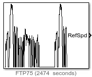
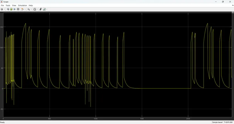
But in the model i am taken FTP75 drive cycle with a time of 2474 sec below i am attaching the image of the drive cycle that i had implemented in my model and its parameters.
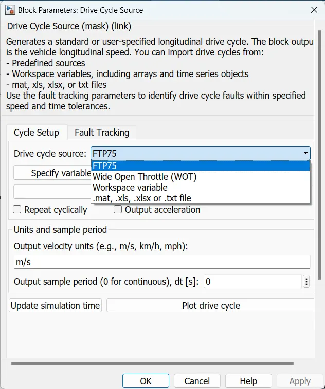
Then it is connected to PID controller driver block of ref_vel port and also connected to scope .
PID driver controler subsystem:
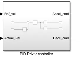
Inside the subsytem shown below
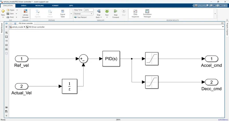
In this subsytem for controlling the speed of the vehicle i am used PID controller, saturation ,unit delay blocks for grnerating the acceleration command & deacceleration command .
the block parameters are shown below
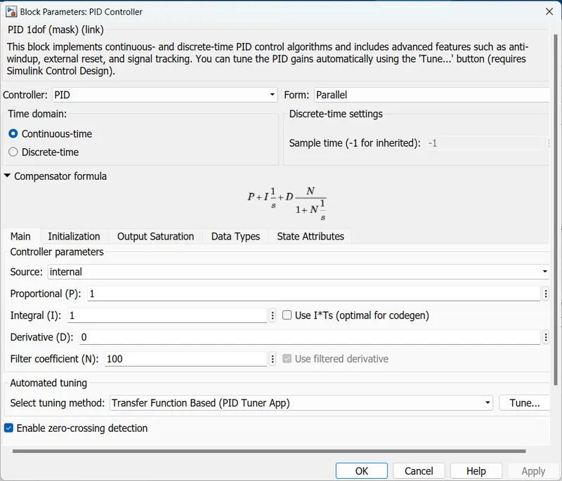
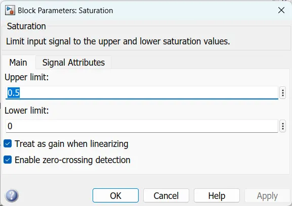
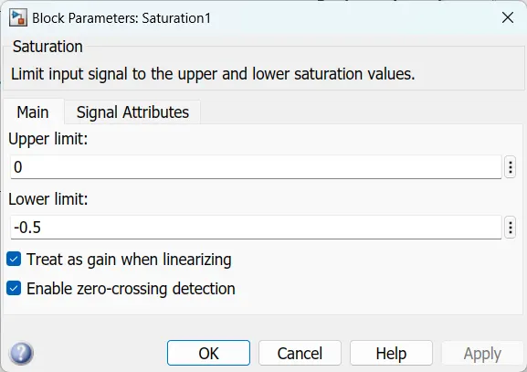
rerference velocity and actual velocity is given to the sum block and it calculate the error signal as difference of two velocity's
and then given to PID controller block and the actual velocity is connected through unit delay the output of pid controller block is connected to two saturation blocks one is for acceleration command and another one deacceleration command.
Motor control sub-system
Below i am attaching the inside of the motor control sub-system
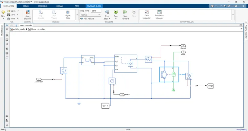
In this above subsystem i am used some blocks that are given below
i) H-bridge
ii) Controlled PWM voltage
iii) DC Motor
iv) Controlled voltage source
Remaining blocks can be considered as a general blocks of the sub-system but those are also important blocks for the smooth and efficient operation, and those blocks are
v) Solver configuration
vi) Electric reference
vii) current sensor
viii) voltage sensor
ix) connection port
x) Scope
xi) mechanical rotational reference
H-bridge:
The H-Bridge block represents an H-bridge motor driver. The block has the following two Simulation mode options:
- PWM — The H-Bridge block output is a controlled voltage that depends on the input signal at the PWM port. If the input signal has a value greater than the Enable threshold voltage parameter value, the H-Bridge block output is on and has a value equal to the value of the Output voltage amplitude parameter. If it has a value less than the Enable threshold voltage parameter value, the block maintains the load circuit using one of the following three Freewheeling mode options:
- Via one semiconductor switch and one freewheeling diode
- Via two freewheeling diodes
- Via two semiconductor switches and one freewheeling diode
The first and third options are sometimes referred to as synchronous operation.
The signal at the REV port determines the polarity of the output. If the value of the signal at the REV port is less than the value of the Reverse threshold voltage parameter, the output has positive polarity; otherwise, it has negative polarity.
The parameters of block shown below
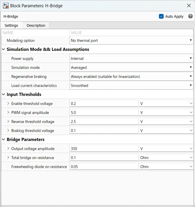
In this block PWM port is connected to controlled pwm voltage then REF & REV ports are connected to electrical referance & BRK port is connected to controlled voltage source and input of the controlled voltage source is connected to decelration comand port of the longitudinal driver block then positive port is connected to motor through current sensor & negative port is connected to electrical ref.
Controlled PWM voltage source:
The Controlled PWM Voltage block represents a pulse-width modulated (PWM) voltage source. You can model electrical or physical signal input ports by setting the Modeling option parameter to either: Electrical input ports — The block calculates the duty cycle based on the reference voltage across its ref+ and ref- ports.
The value of the Output voltage amplitude parameter determines amplitude of the output voltage.
At time zero, the pulse is initialized as high, unless the Pulse delay time parameter is greater than zero, or the demanded duty cycle is zero.
You can use parameters Pulse delay time and Pulse width offset to add a small turn-on delay and a small turn-off advance. This can be useful when fine-tuning switching times so as to minimize switching losses.
In PWM mode, the block has two options for the type of switching event when moving between output high and output low states:
- Asynchronous – Best for variable-step solvers — Asynchronous events are better suited to variable step solvers, because they require fewer simulation steps for the same level of accuracy. In asynchronous mode the PWM switching events generate zero crossings, and therefore switching times are always determined accurately, regardless of the simulation maximum step size.
- Discrete—time – Best for fixed-step solvers — Discrete-time events are better suited to fixed-step operation, because then the switching events are always synchronized with the simulation step. Using an asynchronous implementation with fixed-step solvers may sometimes result in events being up to one simulation step late.
- If you use a fixed-step or local solver and the discrete-time switching event type, the following restrictions apply to the Sample timeparameter value:
- The sample time must be a multiple of the simulation step size.
- The sample time must be small compared to the PWM period, to ensure sufficient resolution.
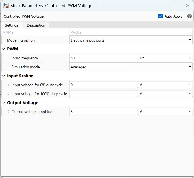
ref+ port is connected to positive terminal of the controlled voltage source, ref- & REF ports are connected to electrical referance and also i am attaching the block parameters as below.
DC motor:
This block represents the electrical and torque characteristics of a DC motor.
The block assumes that no electromagnetic energy is lost, and hence the back-emf and torque constants have the same numerical value when in SI units. Motor parameters can either be specified directly, or derived from no-load speed and stall torque. If no information is available on armature inductance, this parameter can be set to some small non-zero value.
When a positive current flows from the electrical + to - ports, a positive torque acts from the mechanical C to R ports. Motor torque direction can be changed by altering the sign of the back-emf or torque constants.
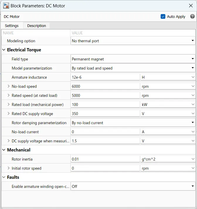
The positive and negative terminals of the dc motor is connected to the positive and negative terminal of the H-bridge and the C terminal of the motor is connected to the mechanical rotational reference and the R port is connected to the Shaft of the transmission system. below i am attaching the image of the DC motor parameters which are considered.
Controlled voltage source:
The block represents an ideal voltage source that is powerful enough to maintain the specified voltage at its output regardless of the current passing through it. The output voltage is V = Vs, where Vs is the numerical value presented at the physical signal port.The block has one physical signal input port and two electrical conserving ports associated with its electrical terminals.
Solver configuration:
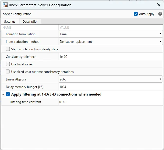
Each physical network represented by a connected Simscape™ block diagram requires solver settings information for simulation. The Solver Configuration block specifies the solver parameters that your model needs before you can begin simulation.
Each topologically distinct Simscape block diagram requires exactly one Solver Configuration block to be connected to it.
It is connected to ground of the system.
Electrical reference:
The Electrical Reference block represents an electrical ground. Electrical conserving ports of all the blocks that are directly connected to ground must be connected to an Electrical Reference block. A model with electrical elements must contain at least one Electrical Reference block.
Battery subsystem:
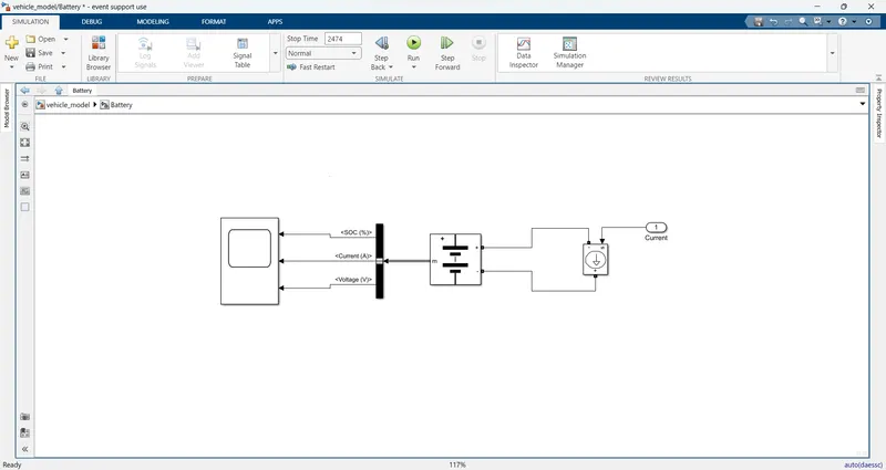
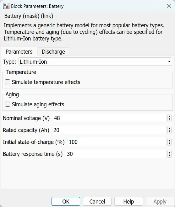
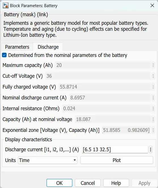
battery parameters are shown below
Transmission subsystem:
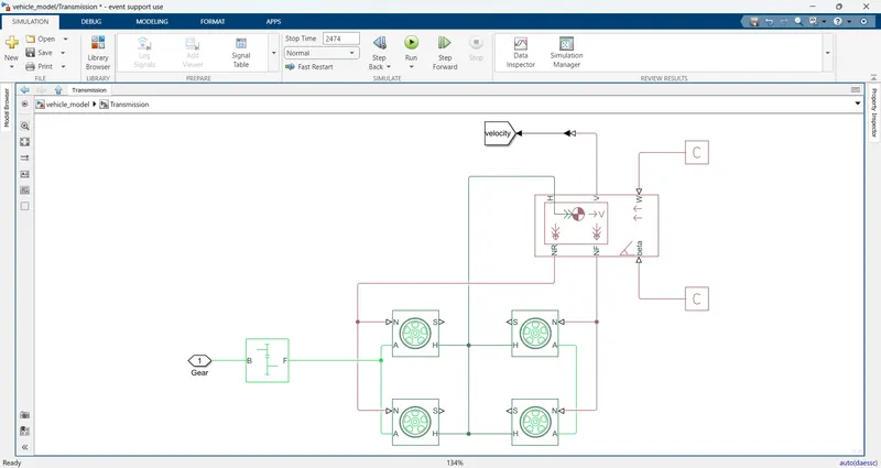
in the above subsystem i am used some blocks that are given below
i) simple gear
ii) tire (magic formula)
iii) vehicle body
simple gear :
Represents a fixed-ratio gear or gear box. No inertia or compliance is modeled in this block. You can optionally include gear meshing and viscous bearing losses.
Connections B (base) and F (follower) are mechanical rotational conserving ports. Specify the relation between base and follower rotation directions with the Output shaft rotates parameter. Optionally include thermal effects and expose thermal conserving port H by setting Friction model to a temperature-dependent setting.
You choose whether the follower axis rotates in the same or opposite direction as the base axis. If they rotate in the same direction, the angular velocity of the follower, ωF, and the angular velocity of the base, ωB, have the same sign. If they rotate in opposite directions, ωF and ωB have opposite signs. You can easily add and remove backlash, faults, and thermal effects.
the below image represents the basic block of the simple gear.
Block parameters are shown below
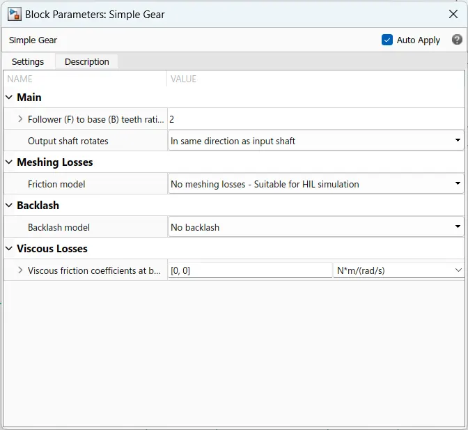
Tire (magic formula) :
The Tire (Magic Formula) block models a tire with longitudinal behavior given by the Magic Formula [1], an empirical equation based on four fitting coefficients. The block can model tire dynamics under constant or variable pavement conditions.
The longitudinal direction of the tire is the same as its direction of motion as it rolls on pavement. This block is a structural component based on the tire road interaction (magic formula) block.
To increase the fidelity of the tire model, you can specify properties such as tire compliance, inertia, and rolling resistance. However, these properties increase the complexity of the tire model and can slow down simulation. Consider ignoring tire compliance and inertia if simulating the model in real time or if preparing the model for hardware-in-the-loop (HIL) simulation. below image represents the tire basic block.
the block parameters are shown below
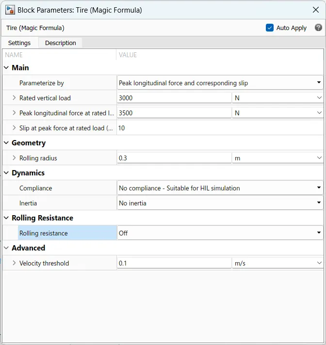
N-port: Physical signal input port associated with the normal force acting on the tire. The normal force is positive if it acts downward on the tire, pressing it against the pavement.
S-port: Physical signal output port associated with the relative slip between the tire and road.
A-axle port: Physical signal output port associated with the relative slip between the tire and road.
H-hub port: Mechanical translational port associated with the wheel hub that transmits the thrust generated by the tire to the remainder of the vehicle.
Vehicle body :
The Vehicle Body block represents a two-axle vehicle body in longitudinal motion. The vehicle can have the same or a different number of wheels on each axle. For example, two wheels on the front axle and one wheel on the rear axle. The vehicle wheels are assumed identical in size. The vehicle can also have a center of gravity (CG) that is at or below the plane of travel.
The block accounts for body mass, aerodynamic drag, road incline, and weight distribution between axles due to acceleration and road profile. Optionally include pitch and suspension dynamics. The vehicle does not move vertically relative to the ground.
The block has an option to include an externally-defined mass and an externally-defined inertia. The mass, inertia, and center of gravity of the vehicle body can vary over the course of simulation in response to system changes.
he vehicle axles are parallel and form a plane. The longitudinal, x, direction lies in this plane and perpendicular to the axles. If the vehicle is traveling on an incline slope, β, the normal, z, direction is not parallel to gravity but is always perpendicular to the axle-longitudinal plane. below picture represents the basic block of the vehicle body
The vehicle body is having the following ports:
NR- It is a rear axle force port.
NF- It is a front axle force port.
Beta – This is a road incline angle port.
H – This port is connected to the horizontal motion of the vehicle’s body.
V – it is a vehicle longitudinal velocity port.
W – is the Headwind speed port.
the block parameters are shown below
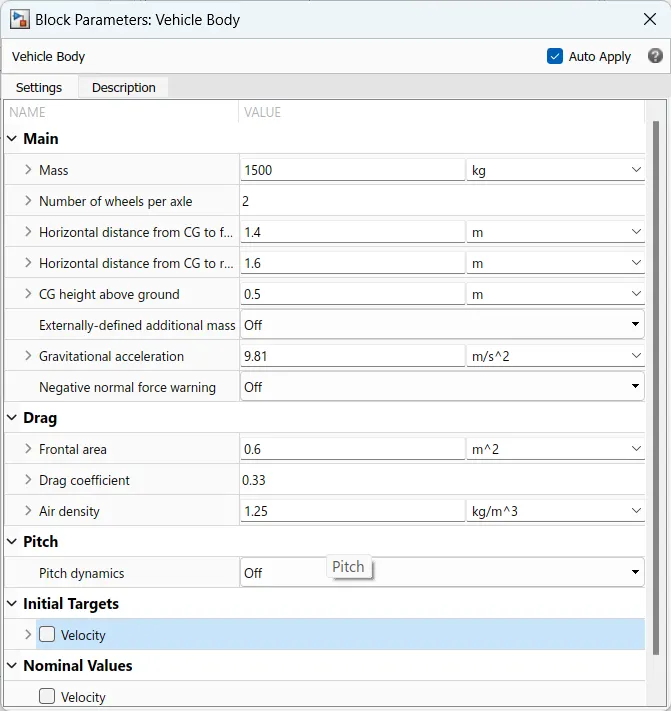
Distance:
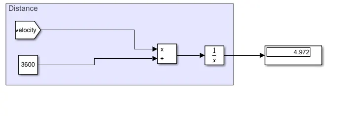
Model explanation:
The simulation time is 2474seconds is taken as per the drive cycle run time. When the simulation is started the Drive Cycle Source is giving the reference speed as an input to the PID controller driver block and this block is having a controller. PID controller is used to generating normalized acceleration and braking commands based on the reference and feedback velocities. The acceleration and deceleration commands are given to the motor controller block.
In the Motor Controller block, two controlled voltage source blocks are taken for acceleration and deceleration ports. When the Acceleration command is generated from the PID controller driver block it is given to the controller voltage source common terminal. At time zero, the pulse is initialized as high unless the duty cycle is set to zero or the Pulse delay time is greater than zero. The output voltage is zero when the pulse is low and is equal to the Output voltage amplitude parameter when high. The duty cycle is set by the input value. This block represents an H-bridge motor drive. The block can be driven by the Controlled PWM Voltage block in PWM or Averaged mode. In PWM mode, the motor is powered if the PWM port voltage is above the Enable threshold voltage. In Averaged mode, the PWM port voltage divided by the PWM signal amplitude parameter defines the ratio of the on-time to the PWM period. Using this ratio and assumptions about the load, the block applies an average voltage to the load that achieves the correct average load current. The Simulation mode parameter value must be the same for the Controlled PWM Voltage and H-Bridge blocks. The PWM block positive output port is connected to the current sensor Positive input port. This current sensor converts the current measured in any electrical branch into a physical signal proportional to the current. The connection I is a physical signal port that outputs the current value. This output is given to the battery subsystems controlled current source common terminal. The motor positive terminal is connected to the current sensor negative terminal. Motor mechanical R port is connected to the simple gear. A voltage sensor is placed in parallel with DC Motor to measure the voltage. A solver is placed at common ground. In the transmission subsystem Gear is the input signal and the vehicle body is connected to the tires.
The vehicle body has the inclination angle and wind force ports these are connected to PS constant blocks. This vehicle body has an H port this port is connected to the wheel’s hub port of all four wheels. Tires force N port is connected to NR and NF these are rear force and font force. V port is the velocity of the vehicle body is output for the longitudinal driver block which is feedback.
Run the simulation and then the results are shown below.
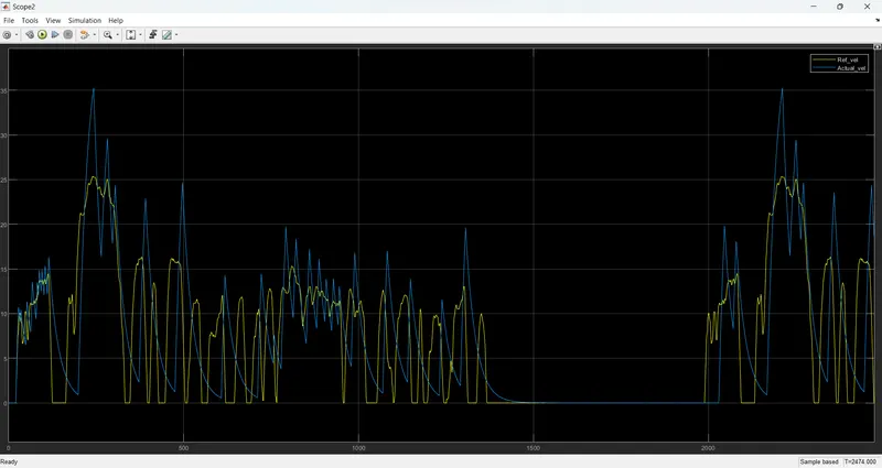
In this scope, we can observe the two plots which are the Drive cycle source and Feedback velocity. These plots are indicated in different colours yellow colour plot is the Drive cycle source and the blue one is feedback velocity. We can observe that both plots are similar with small variations. Sudden changes in acceleration and braking apply to the vehicle. Inclination angle and wind force acting on the vehicle also affect the vehicle performance. In real-time vehicle running vehicle drag force, acceleration, braking, and wind force are considered. These are affecting the vehicle speed as compared with reference drive cycle speed.
Cell Voltage,SOC & current is shown below
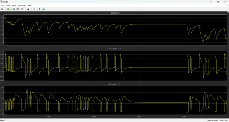
The first plot is SOC of the cell and the SOC is dropped from 100 to 75%
The second plot shown as current of the cell
The third plot is shown as voltage of the cell
The motor voltage is shown below