Project 1 Mechanical design of battery pack
Battery pack capacity: 18 kWh
Cell: ANR26650M1-B
Prepare a detailed battery pack drawing along with its enclosure. State your assumptions.
The ANR26650M1-B is the next generation of A123 Systems’ pioneering 26650 cylindrical cells, now with greater power and energy density and lower impedance. This versatile lithium-ion cell is suitable for a wide variety of applications and system designs. Proven performance in the toughest conditions, combining durability, reliability, and safety, the ANR26650 cell offers an excellent combination of price-performance.
A123’s high-performance Nanophosphate lithium iron phosphate (LiFePO4) battery technology delivers high power and energy density combined with excellent safety performance and extensive life cycling in a lighter weight, more compact package. Our cells have low-capacity loss and impedance growth over time as well as high usable energy over a wide state of charge (SOC) range, allowing our systems to meet end-of-life power and energy requirements with minimal pack oversizing.
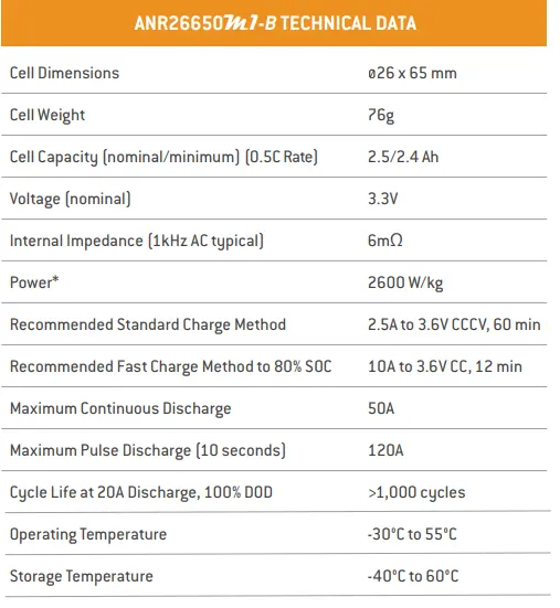
To calculate all the parameters, we need the data of the cell ANR2665031-B, for that we have to check the datsheet of the cell. The following figure shows the basic charactersitics of the cell given in its datasheet.
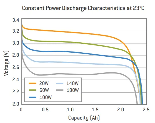
The following are the constant power discharge characteristics of the cell at 23°C temperature. This characteristics are drawn for different power ratings of the cell. If we observe the plot, as the power of the cell increases the voltage and its discharging characteristics are reduced.
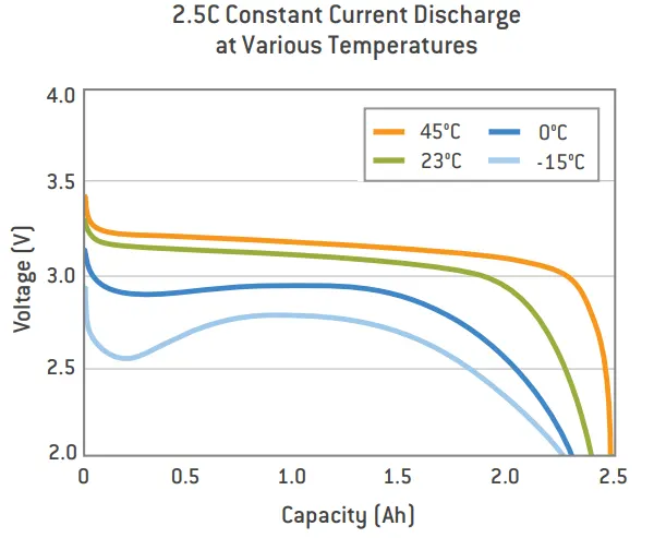
The following figure shows the 2.5C rate Constant current discharge charactersistics at different temperatures, If we observe the plot it can be say that, the cell characteristics are varies with respect to the temperature changes. So we have to operate the cells within its nomial temperature zone. the temperature is 45degc then the voltage of a cell is 3.4V and the temperature of cell is -15degc the voltage is 2.9V so the cell has operate at minimum temperature condition is good.
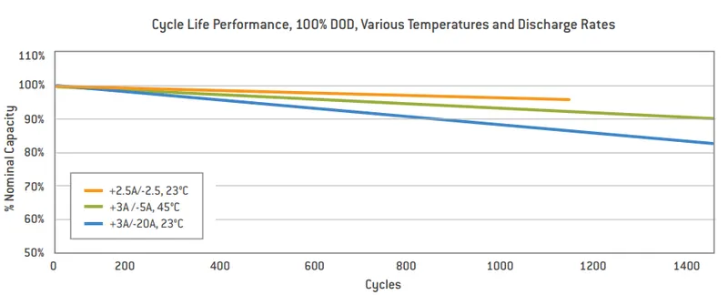
The following figure shows the cycle life performance, 100% DOD (Depth Of Discharge), various temperatures and discharge rates of the cell.
A battery pack is a device that stores electrical energy to provide power to an electrical system, such as an electric vehicle (EV) or an energy storage system (ESS). The energy is stored in cells that are all connected to one another in the battery pack.
To provide sufficient power, battery packs require a minimum voltage level which a single cell cannot achieve. Multiple cells are therefore connected in series to boost voltage. Some designs use small-capacity cells. To achieve the desired battery energy, cells are connected in parallel to boost capacity. Cells connected in parallel provide power as if they were a single, larger cell.
Battery packs are made of multiple, smaller sections called battery modules (or sub packs). These modules include a smaller number of cells connected in series and parallel. They are usually at a lower voltage, which is safe for handling. Modules facilitate servicing when only a few cells are defective and if they can be replaced without replacing the entire battery. EV batteries are typically made of 4 to 40 modules connected in series to one another.
The voltage level of the battery determines the maximum electrical power which can be delivered continuously. As power is the product of voltage and current. The higher the current, te bigger the diameter of the high voltage wire and higher the thermal losses. For this reason the current should be limited to a maximum and the nomial power obtained by having a higher voltage. For our modelling of pack, considering the nominal voltage of 264V. All high voltage battery packs are made up from battery cells arranged in strings and modules. A battery cell can be regarded as the smallest divison of the voltage.
Individual battery cells may be grouped in parallel and/or series as modules. Further, battery modules can be connected in parallel and/or series to create a battery pack. Depending on the battery parameters there may be several vlevels of modularity. The total battery pack voltage is dertermined by the number of cells connected in series. The current capcity of the battery pack is determined by the number of cells connected in parallel. Following figures gives the information of series and parallel connections.
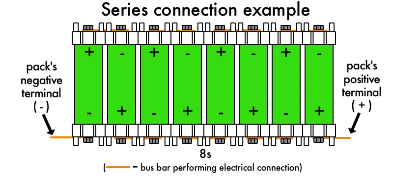
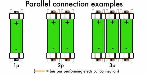
Based on the cell parameters provided by the manufacturers, we can calculate the energy content, volume, gravimetric density and volumetric density for each cell.
The following figure shows the dimentions of the ANR2665031-B cell.
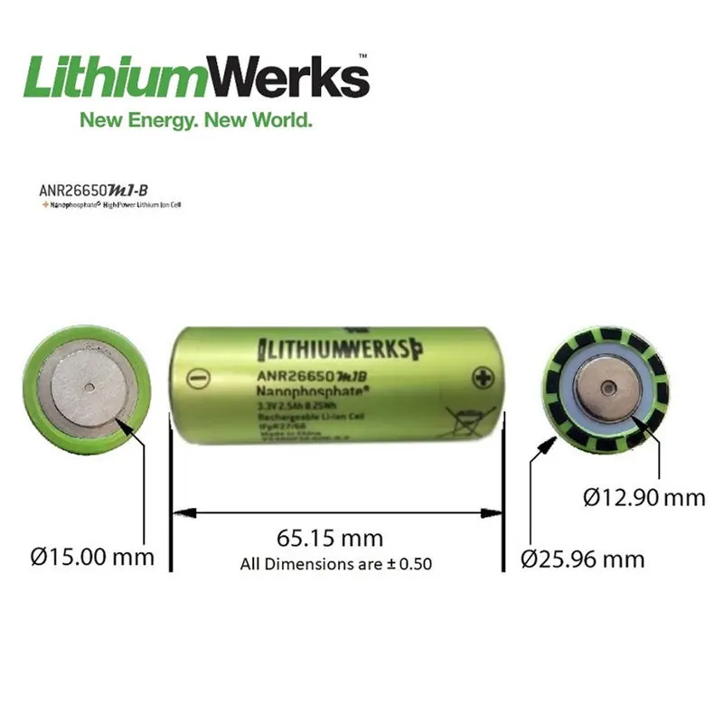
Now let’s calculate the electrical and the mechanical parameters of the battery pack which is helpful to say the total electrical specification of the pack and the calculations which are helpful for the battery pack packing in the module
From the datasheet, the following parameters are considered for the calculation.
Cell dimensions = 26mm×65mm (diameter of cell×height of cell)
Cell weight = 76g
Nominal cell capacity = 2.5Ah
Nominal voltage = 3.3V
Power = 2600W/kg
Continuous C-Rate = 10
Peak C-Rate = 24
Volume of Cell (For cylindrical) = πr²h
Radius of a cell = Diameter/2 = 26/2 = 13mm = 0.013m
Height of a cell = 65mm = 0.065m
Volume of a Cell = πr²h = 3.14×0.013²×0.065 = 3.45×10^-5 m³
Volume of Cell = 3.45×10^-5 m³
Now will calculate the energy of each cell,
Cell energy = Cell capacity × Cell voltage
Cell energy = 2.5 × 3.3 = 8.25
Cell Energy = 8.25Wh
Now we canculate total energy of cell by using each cell energy,
Battery pack energy density = Cell energy ÷ Volume of a cell
Battery energy = 8.25 ÷ 3.45×10^-5 = 239130.435
Battery pack energy density = 239130.435 Wh/m³.
Gravimetric Energy = Cell Energy ÷ Weight of cell
Weight of cell = 76g = 0.076kg
Gravimetric Energy = 8.25÷0.076 = 108.55
Gravimetric Energy = 108.55Wh/kg.
In our challenge we have to make a battery pack capacity of 18kWh = 18000Wh
Number of cells connected in series = Battery pack voltage ÷ Voltage of each battery cell
Let us assume the battery pack voltage required is 300.5V.
No. of cells connected in series = 300.5÷3.3 = 91
Number of cells connected in series = 91 cells.
Energy of a string = No. of cells connected in series × Energy of a battery pack
Energy of a string = 91×8.25 = 750.75
Energy of a string in series = 750.75Wh.
Number of cells connected in Parallel = Battery pack Capacity ÷ Energy of a string in series
No. of cells connected in Parallell = 18000÷750.75 = 23.9
Number of cells connected in Parallel = 24 cells.
Battery pack capacity = Number of cells connected in Parallel × Capacity of a cell
Battery pack capacity = 24×2.5 = 60
Battery pack capacity = 60Ah.
Total number of cells in a battery pack = Number of cells connected in series × Number of cells connected in Parallel
Total number of cells in a battery pack = 91×24 = 2184
Total number of cells in a battery pack = 2184 cells.
Weight of the battery pack = Total number of cells in a battery pack × Weight of a cell
Weight of the battery pack = 2184×0.076 = 170.24
Weight of the battery pack = 165.98kg.
Volume of the battery pack = Total number of cells in a battery pack × Volume of a cell
Volume of the battery pack = 2184×3.45×10^-5 = 0.0753
Volume of the battery pack = 0.0753 m³.
String peak current = Peak C-Rate of a cell × Cell capacity
String peak current = 24×2.5 = 60
String peak current = 60A.
Battery pack peak current = String peak current × Number of cells connected in Parallel
Battery pack peak current = 60×24 = 1440
Battery pack peak current = 1440A.
Battery pack Peak power = Battery pack peak current × Battery pack voltage
Battery pack Peak power = 1440×300.5 = 432720W = 432.72kW
Battery pack Peak power = 432.72kW.
String continuous current = Continuous C-Rate of a cell × Capacity of a cell
String continuous current = 10×2.5 = 25
String continuous current = 25A.
Battery pack continuous current = String continuous current × Number of cells connected in Parallel
Battery pack continuous current = 25×24 = 600
Battery pack continuous current = 600A.
Battery pack continuous power = Battery pack continuous current × Battery pack voltage
Battery pack continuous power = 600×300.5 = 180300W = 180.3kW
Battery pack continuous power = 180.3kW.
Report of Calculated parameters: All calculated parameters all listed below in the table.
|
Parameter Name |
Parameter Value |
|
Volume of Cell |
3.45×10^-5 m³ |
|
Volume of the battery pack |
0.07728 m³ |
|
Weight of the battery pack |
170.24kg |
|
Cell Energy |
8.25Wh |
|
Battery pack energy density |
239130.435 Wh/m³ |
|
Gravimetric Energy |
108.55Wh/kg |
|
Number of cells connected in series |
91 cells |
|
Number of cells connected in Parallel |
24 cells |
|
Energy of a string in series |
750.75Wh |
|
Battery pack capacity |
60Ah |
|
Total number of cells in a battery pack |
2184cells |
|
String peak current |
60A |
|
Battery pack peak current |
1440A |
|
Battery pack Peak power |
432.72kW |
|
String continuous current |
25A |
|
Battery pack continuous current |
600A |
|
Battery pack continuous power |
180.3kW |
Before moving to the enclosure procedure we have to know the few steps for making a battery pack that is Cell → Battery module → Battery pack.
Battery cell is basic unit of a Li-ion battery that exerts electric energy by charging and discharging. Made by inserting cathode, anode, seperator and electrolyte into a rectangular aluminium case.
Battery module is a battery assembly put into a frame by combining a fixed umber of cells to protect the cells from external shocks, heat or vibration.
Battery pack is the final shape of the battery system installed to an electric vehicle. Composed of modules and various control/protection systems including a BMS (Battery Management System), a cooling system etc.
Now lets get into the enclosure procedure :
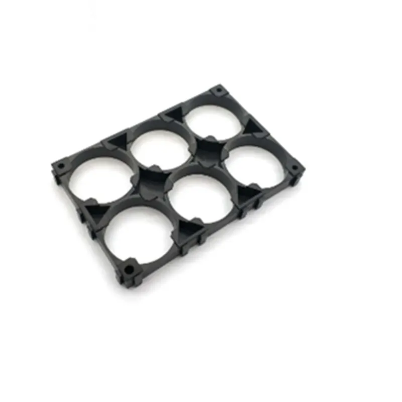
Battery holders:
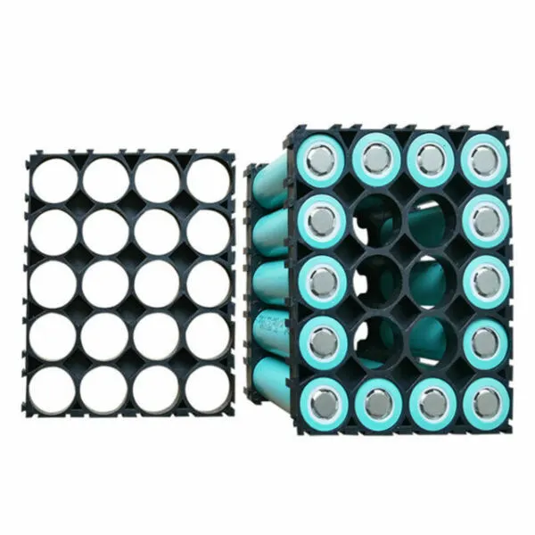
Battery holders are designed to support commercial, industrial or OEM batteries. They allow for safe retention, and easy and fast replacement of the battery.
Types of battery holders include:
- Plastic - Plastic holders are fabricated from molded plastic.
- Metal - Metal holders similar in form to molded plastic holders, but with flexible metal clips into which the batteries are inserted.
- Battery snaps - Battery snaps are snap terminals, typically for 9V batteries.
- Coin cell - Coin cell battery holders are for round coin cell batteries.
- Component clips - Component chips are flexible clips into which batteries are inserted and held under constant spring tension.
- Battery racks - Battery racks range in size from those that contain a single battery to those that contain multiple batteries. They are usually available in one, two or multiple tiers.
- Battery cabinets - Battery cabinets are basic battery enclosures.
- Single cell - Single cell battery holders hold only one battery.
- Multiple cell - Multiple cell holders hold 2 or more batteries.
Common connection types for the connection of battery holders to the device include:
-
Surface mount - Surface mount holders can be mounted on the surface of the device. This can be accomplished through solder tabs or an adhesive base.
-
Through-pin PC or socket mount - Through-pin PC or socket mount holders are mounted on a printed circuit board (PCB). PCB mounting is via pins that extend through holes in the board.
-
Solder lugs - Battery holders with solder lugs are soldered to the device.
-
Snap terminals - A holder with snap terminals can be snapped to the device.
-
Wire leads - Batteries can also be connected to the device via wire leads.
The enclosure is able to secure the modules during sudden accelerations or decelerations from crash scenarios, allows for air flow to cool the cells, and allows for convenient serviceability of the modules. As the batteries are connected in series and parallel according to the capacity of the pack. After the battries are connected they are assembeled in the cells.
Nickel strips:

This nickel strip is made of 99.6% pure nickel. It is best suitable for spot welding in the 18650/32650 Lithium Ion/phosphate battery pack. The nickel strips get soldered very quickly with normal soldering material and with high tensile tension and low resistivity.
It is mostly used in spot welding and soldering during battery pack building. The nickel strip provides high corrosion resistance over time. If you don’t want to affect the current transfer rate of a battery even after a long use then this is the best choice.
- Made of 99.96% pure nickel
- High tensile tension
- Low resistivity
- High resistance to corrosion
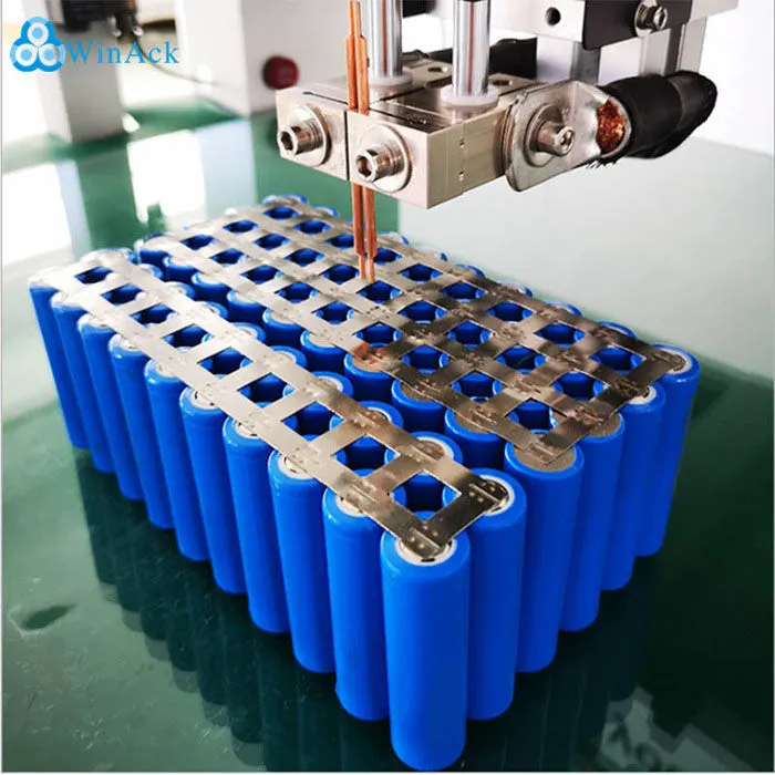
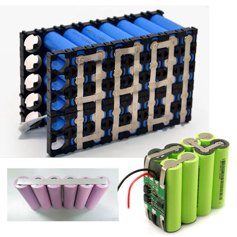
Battery Connection Welding metal Strip with 99.96% Pure Nickel -10Pcs. made of Pure Nickel Plate with 99.96% Pure Nickel Strap Strips Sheets.
It is generally useful in the welding of battery points together to connect the batteries in combinations. These Nickel strips are popular because of their good performance while soldering as it gets soldered very quickly; easily with normal soldering metal with High tensile tension and Low resistivity.
They are mainly useful in the manufacture of nickel-hydrogen batteries, lithium batteries; high magnification power tools batteries, laptop batteries, battery combination with HM.
Battery enclosure:
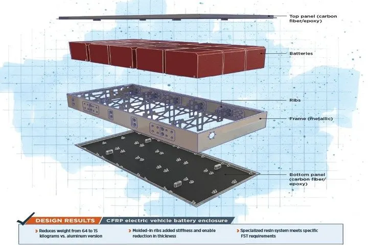
The most common battery enclosures are made from plastic materials that are resistant to alkaline solutions and have a high impact strength. Metal housings are sometimes used, but metal requires careful design and assembly to avoid shorting of the cells in the battery pack. Aluminum is not recommended for enclosures because if cell leakage does occur, the electrolyte will react with the aluminum.
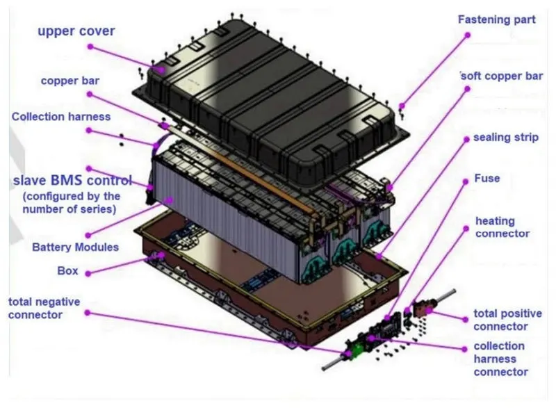
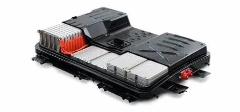
Final battery pack:
In the following figure we can see the arrangement of modules of the battery pack which are used in electric vehicles
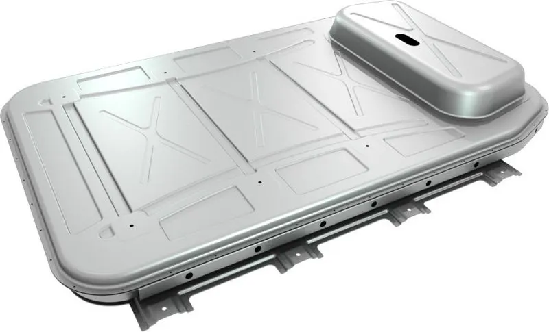
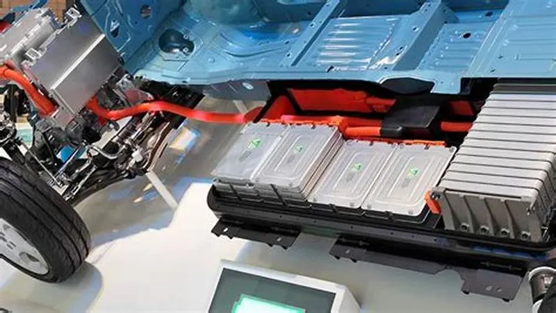
so the enclosure procedure, the electrical and the mechanical parameters of the battery pack are also calculated of the ANR26650M1-B is done with the relevent images