Project 2 Adaptive Cruise Control
Aim:
- Main object of this project is to Create Model Based Development Simulink model for Adaptive cruise control as per the requirement specified.
- Requirement tagging for requirement-1, requirement-2 & requirement-3 subsystems in the Simulink model with the respective selection in word document.
- Create a data dictionary and linked to the developed model.
- Code generation using embedded coder for the developed model.
Introduction:
Adaptive Cruise Control Feature for passenger cars allows the host vehicle to adapt to the speed in line with the flow of traffic. Driving in heavy traffic or keeping a safe distance to the preceding vehicle calls for a high level of concentration. The Adaptive Cruise Control feature can reduce the stress on the driver by automatically controlling the vehicle speed & maintaining a predefined minimum distance to the preceding vehicle. As a consequence, the driver enjoys more comfort & can concentrate on the road little better.
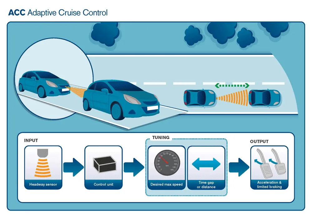
A radar sensor is usually at the core of the Adaptive Cruise Control. Installed at the front of the vehicle, the system permanently monitors the road ahead. As long as the road ahead is clear, cruise control feature maintains the speed set by the driver. If the system spots a slower vehicle within its detection range, it gently reduces speed by releasing the accelerator or actively engaging the brake control system. If the vehicle ahead speeds up or changes lanes, the cruise control automatically accelerates to the driver’s desired speed.
Standard Adaptive Cruise Control can be activated from speeds of around 30 km/h (20 mph) upwards and supports the driver, primarily on cross-country journeys or on freeways. The cruise control stop & go variant is also active at speeds below 30 km/h (20 mph). It can maintain the set distance to the preceding vehicle even at very low speeds and can decelerate to a complete standstill. When the vehicle remains stopped longer, the driver needs only to reactivate the system, for example by briefly stepping on the gas pedal to return to cruise control mode. In this way, cruise control stop & go supports the driver even in heavy traffic and traffic jams.
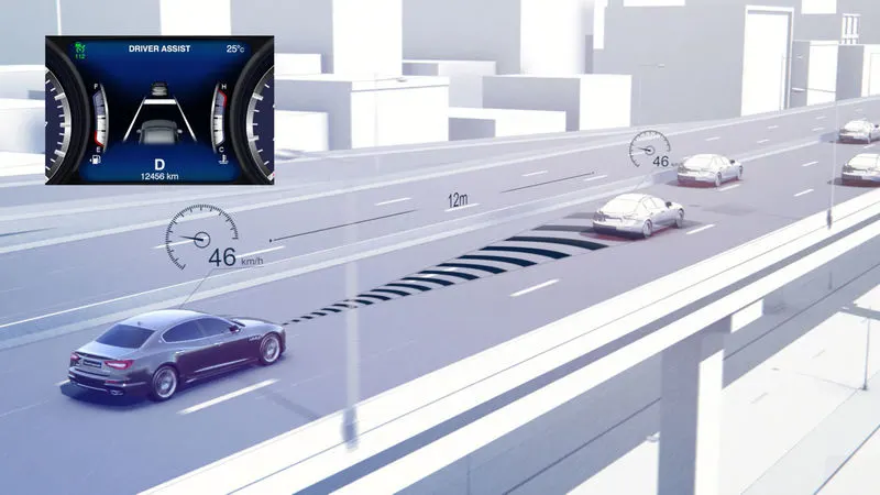
Since Adaptive Cruise Control is a comfort and convenience system, brake interventions and vehicle acceleration only take place within defined limits. Even with Adaptive Cruise Control switched on, it remains the driver’s responsibility to monitor the speed and distance from the vehicle in front.
Objective of Mini Project:
- Developing Adaptive Cruise Control feature as per the Requirement Document using MATLAB Simulink.
- Follow all the MBD related processes: Requirement Tagging & Traceability, SLDD creation, Configuration Parameter changes, Model Advisor check & Code Generation.
- In Configuration Parameters: enable “Support Floating Numbers” under Code Generation settings.
- Use Embedded Coder to generate the code.
- If choosing code generation, Storage class for Input signals: ImportedExtern; Storage class for Output signal: Export to File; Storage class for local signals: localizable; Storage class for calibration signals: Const.
- Choose sample time for all signals as 0.01s
Adaptive Cruise Control Model:
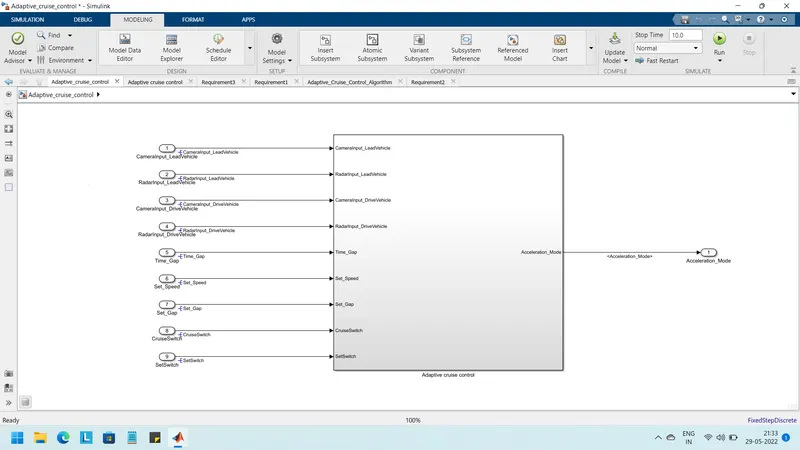
Lead _Vehicle, Drive _Vehicle & ACC_Algorithm subsystems present inside Adaptive _Cruise Control Subsystem
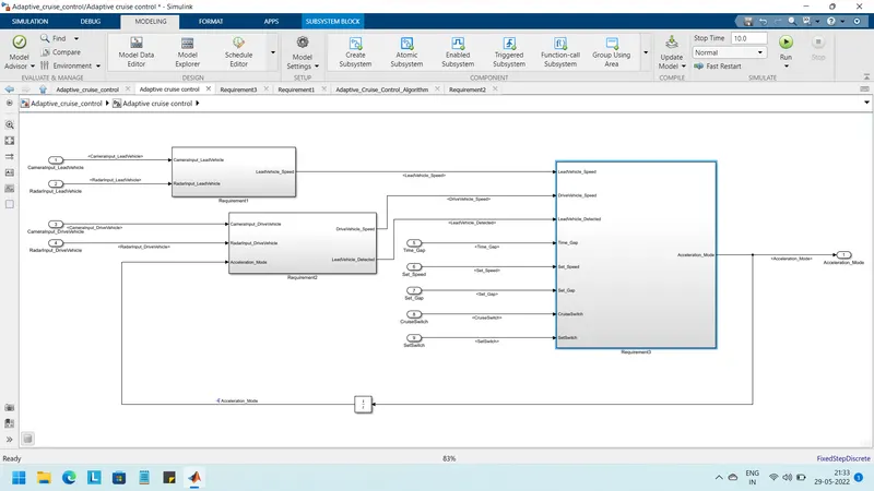
Requirement 1- Lead Vehicle
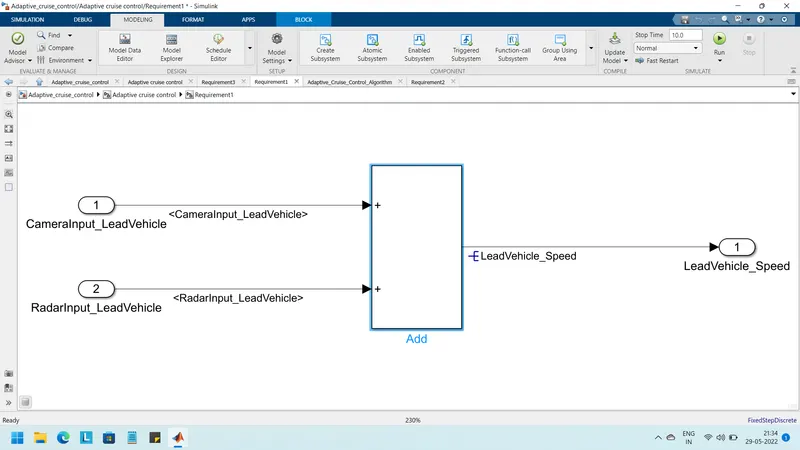
- Lead Vehicle is a vehicle which is driving in the road ahead of our drive vehicle. Two input signals (Signal Name: CameraInput_LeadVehicle & RadarInput_LeadVehicle).
- Ideally sensor fusion techniques will be deployed to process & analyze data from camera & radar. For complexity reasons, let’s not adapt to any such algorithms.
- We can simply add both the radar & camera inputs & the corresponding output is read as Speed profile output (Signal Name: LeadVehicle_Speed).
- Speed data of the lead vehicle is critical in implementing the Adaptive Cruise Control algorithm.
Blocks used in this subsystem:
Inport block:
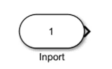
Inport blocks in a subsystem represent inputs to the subsystem. A signal arriving at an input port on a Subsystem block flows out of the associated Inport block in that subsystem. The Inport block associated with an input port on a Subsystem block is the block whose Port number parameter matches the relative position of the input port on the Subsystem block. For example, the Inport block whose Port number parameter is 1 gets its signal from the block connected to the topmost port on the Subsystem block.
Outport block:
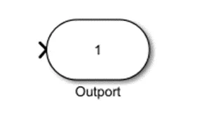
- Outport blocks in a subsystem represent outputs from the subsystem. A signal arriving at an Outport block in a subsystem flows out of the associated output port on that Subsystem block. The Outport block associated with an output port is the block whose Port number parameter matches the relative position of the output port on the Subsystem block. For example, the Outport block whose Port number parameter is 1 sends its signal to the block connected to the topmost output port on the Subsystem block.
Sum block:

The Sum block performs addition or subtraction on its inputs. The Add, Subtract, Sum of Elements, and Sum blocks are identical blocks. This block can add or subtract scalar, vector, or matrix inputs. It can also collapse the elements of a signal and perform a summation.
Requirement 2 – Drive Vehicle:
- Drive Vehicle is the vehicle driven by the user & this is the vehicle which has ACC algorithm in it.
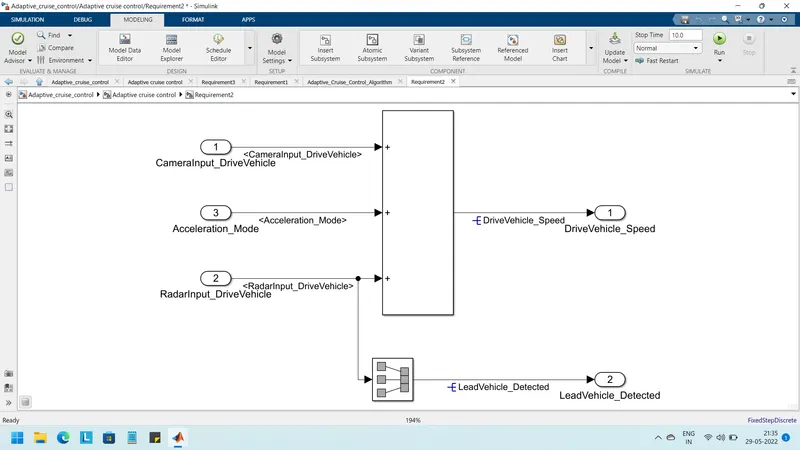
- Like the Lead Vehicle, Drive Vehicle algorithm also has 2 input signals (Signal Name: CameraInput_DriveVehicle, RadarInput_DriveVehicle) & one signal coming as an Input to this subsystem (Signal Name: Acceleration_Mode) – three inputs into this requirement in total.
- Like the above requirement, sensor fusion techniques will also be deployed here, for complexity reasons we are ignoring them.
- Two output signals come from this subsystem (Signal Name: DriveVehicle_Speed & LeadVehicle_Detected).
- Signal DriveVehicle_Speed is summation of three input signals mentioned above & LeadVehicle_Detected is renamed from Input Signal RadarInput_DriveVehicle by mere use of Signal Conversion
- block.
Block used in the subsystem:
Signal conversion:
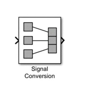
- The Signal Conversion block converts a signal from one type to another.
Requirement 3 – Adaptive Cruise Control Algorithm:
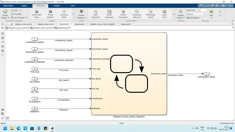
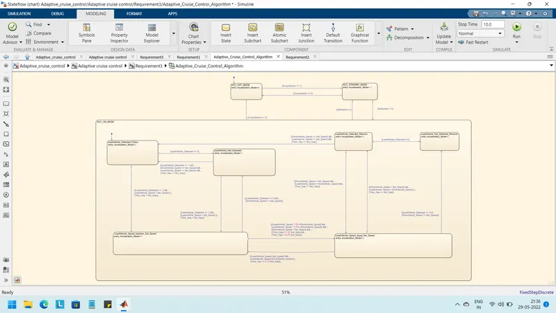
- Adaptive Cruise Control feature has 3 major modes of operation: OFF Mode, STANDBY Mode & ON Mode. This particular requirement has to be implemented as state machine logic in Simulink.
- The input signals to this state machine system are (Signal Name: Time_Gap, Set_Speed, Set_Gap, CruiseSwitch, SetSwitch).
- Also, the output signals (Signal Name: DriveVehicle_Speed & LeadVehicle_Detected) from requirement-2 is fed back as an input signal into this state machine block.
- Additionally, output signal (Signal Name: LeadVehicle_Speed) from requirement-1 is given as an input signal to this state machine block as well.
- Output from this subsystem is a signal (Signal Name: Acceleration_Mode) which governs the vehicular speed of the drive vehicle which automatically adjusts its speed & velocity to match the lead vehicle.
Requirement 3a – ACC OFF MODE state logic:
- This is the default state inside state machine logic. Output signal Acceleration_Mode is at value 0 in this state.
- This state is governed by input signal CruiseSwitch.
- If CruiseSwitch is equal to 1, state ACC STANDBY mode will get activated. If CruiseSwitch is equal to 0, state ACC OFF mode will get activated, from either ACC ON mode or ACC STANDBY mode
Requirement 3b – ACC STANDBY MODE state logic:
- This is the second activated state inside state machine logic. Output signal Acceleration_Mode is at value 1 in this state.
- This state is governed by both input signals CruiseSwitch & SetSwitch.
- If CruiseSwitch is equal to 1, state ACC STANDBY mode will get activated. If CruiseSwitch is equal to 0, state ACC OFF mode will get activated, from either ACC ON mode or ACC STANDBY mode
- If SetSwitch is equal to 1, state ACC ON mode will get activated. If SetSwitch is equal to 0, state ACC STANDBY mode will get activated.
Requirement 3c – ACC ON MODE state logic:
This state will be activated when input signal SetSwitch is equal to 1. There are 6 sub states to this state logic: They are:
- LeadVehicle_Detected_Follow (Default)
- LeadVehicle_Not_Detected
- LeadVehicle_Detected_Resume
- LeadVehicle_Not_Detected_Resume
- LeadVehicle_Speed_lessthan_Set_Speed
- LeadVehicle_Speed_equal_Set_Speed
Requirement 3c (i) – LeadVehicle_Detected_Follow (ACC ON MODE):
- This is the default sub state inside ACC ON MODE state. Output signal Acceleration_Mode is equal to 2.
- Condition to transit from LeadVehicle_Detected_Follow to LeadVehicle_Not_Detected; Input signal condition LeadVehicle_Detected == 0.
- Condition to transit from LeadVehicle_Detected_Follow to LeadVehicle_Speed_lessthan_Set_Speed; Input Signals condition (LeadVehicle_Detected == 1) && (LeadVehicle_Speed < Set_Speed) || (Time_Gap < Set_Gap).
Requirement 3c (ii) – LeadVehicle_Not_Detected (ACC ON MODE):
- Output signal Acceleration_Mode is equal to 1.
- Condition to transit from LeadVehicle_Not_Detected to LeadVehicle_Detected_Follow; Input signals condition [(LeadVehicle_Detected==1) && (DriveVehicle_Speed == Set_Speed) && (LeadVehicle_Speed >= Set_Speed) && (Time_Gap >= Set_Gap)]
- Condition to transit from LeadVehicle_Not_Detected to LeadVehicle_Speed_lessthan_Set_Speed; Input signals condition [(LeadVehicle_Detected == 1) && (LeadVehicle_Speed < Set_Speed) || (Time_Gap < Set_Gap)]
Requirement 3c (iii) – LeadVehicle_Detected_Resume (ACC ON MODE):
- Output signal Acceleration_Mode is equal to 3.
- Condition to transit from LeadVehicle_Detected_Resume to LeadVehicle_Detected_Follow; Input signals condition [(DriveVehicle_Speed == Set_Speed) && (LeadVehicle_Speed >= Set_Speed) && (Time_Gap >= Set_Gap)]
- Condition to transit from LeadVehicle_Detected_Resume to LeadVehicle_Not_Detected_Resume; Input signal condition LeadVehicle_Detected==0.
- Condition to transit from LeadVehicle_Detected_Resume to LeadVehicle_Speed_equal_Set_Speed; Input Signal condition [(DriveVehicle_Speed < Set_Speed) && (LeadVehicle_Speed > DriveVehicle_Speed) && (Time_Gap >= Set_Gap)]
Requirement 3c (iv) - LeadVehicle_Not_Detected_Resume (ACC ON MODE):
- Output signal Acceleration_Mode is equal to 1.
Requirement 3c (v) - LeadVehicle_Speed_lessthan_Set_Speed (ACC ON MODE):
- Output signal Acceleration_Mode is equal to 4.
- Condition to transit from LeadVehicle_Speed_lessthan_Set_Speed to LeadVehicle_Not_Detected; Input signal condition [(LeadVehicle_Detected == 0) && (DriveVehicle_Speed == Set_Speed)]
- Condition to transit from LeadVehicle_Speed_lessthan_Set_Speed to LeadVehicle_Speed_equal_Set_Speed; Input signals condition [((LeadVehicle_Speed*1.25>=DriveVehicle_Speed) && (LeadVehicle_Speed * 0.75<=DriveVehicle_Speed)) && (DriveVehicle_Speed < Set_Speed) && ((Time_Gap<=1.25*Set_Gap) && (Time_Gap >=0.75*Set_Gap))]
Requirement 3c (vi) - LeadVehicle_Speed_equal_Set_Speed (ACC ON MODE):
- Output signal Acceleration_Mode is equal to 5.
- Condition to transit from LeadVehicle_Speed_equal_Set_Speed to LeadVehicle_Not_Detected_Resume; Input signal conditions is [(LeadVehicle_Detected == 0) || (DriveVehicle_Speed <= Set_Speed)]
- Condition to transit from LeadVehicle_Speed_equal_Set_Speed to LeadVehicle_Detected_Resume; Input signal conditions [(DriveVehicle_Speed < Set_Speed) && (LeadVehicle_Speed > DriveVehicle_Speed) || (Time_Gap >= Set_Gap)]
- Condition to transit from LeadVehicle_Speed_equal_Set_Speed to LeadVehicle_Speed_lessthan_Set_Speed; Input signals conditions [(LeadVehicle_Speed<set_speed) && (leadvehicle_speed<drivevehicle_speed)||(time_gap==0.75*set_gap).
Requirement tagging:
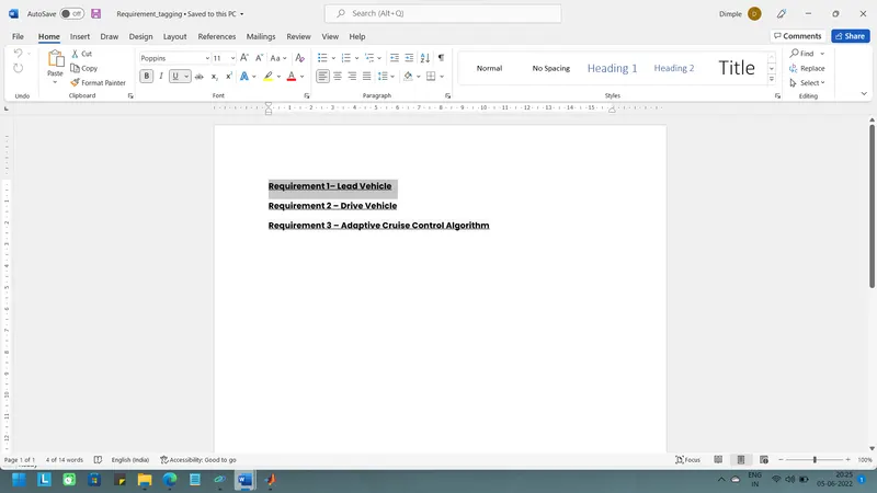
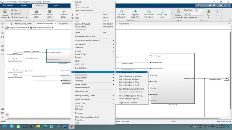
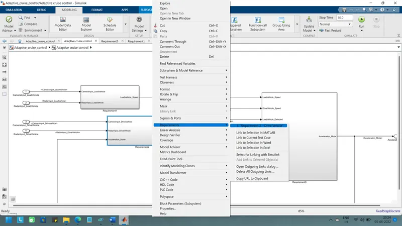
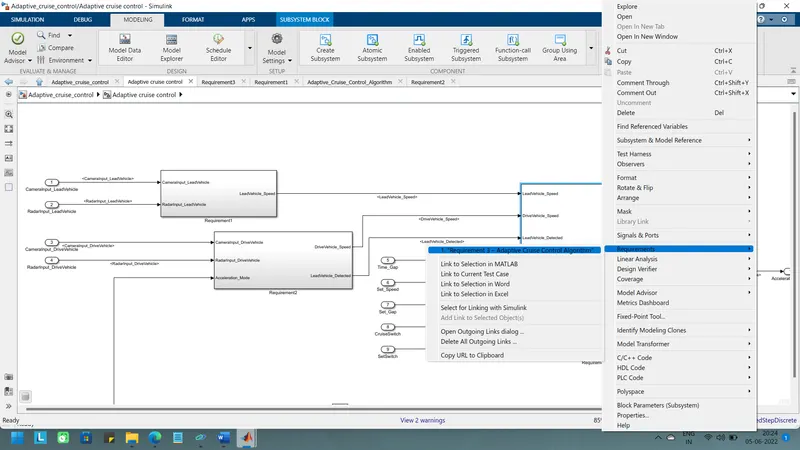
The requirements ‘requirement-1’ , ‘requirements-2’ & requirement-3 as provided in the requirements word document are tagged to their corresponding subsystem in the Simulink model. tagging a requirement in Simulink model is to first highlight the requirement statement in the word document, then right click on the subsystem in the model that has to be tagged, then select requirements, and then select ‘link to selection in word’.
For tagging select the word in document as shown below.
After tagging the subsystem is like shown below.
For requirement-2
For requirement-3
Creation of Simulink data dictionary
A simulink data dictionary (SLDD)file is created that contains input, output signals and calibration parameters used in the model. SLDD file is created by clicking the modelling then model properties, then ‘external data’ and specifying a file name for the data dictionary.
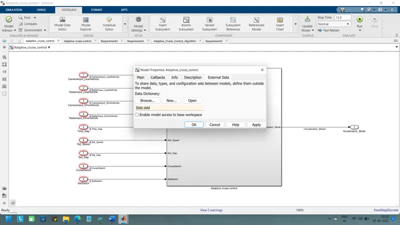
After creation of sldd like below
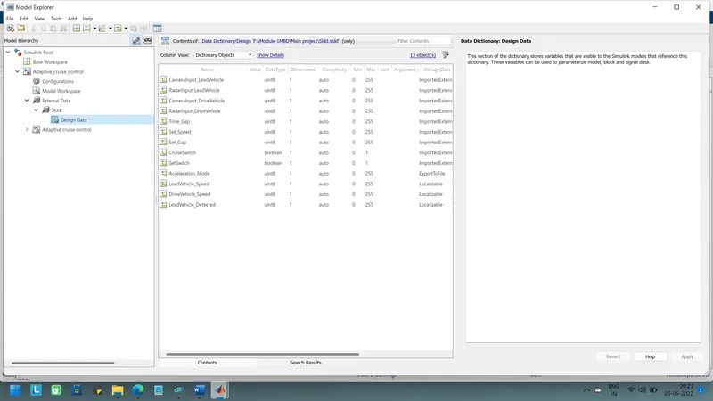
solver settings Type as fixed step and solver as discrete beacuase of Discrete solvers are used for solving purely discrete models. They compute only the next simulation time step for a model.And also select step size is as 0.01.
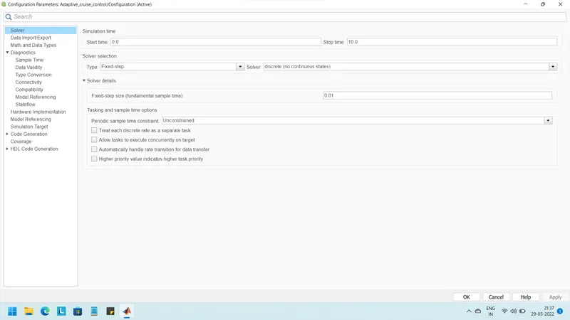
For code generation purpose change the settings in configuration parameters select the system target file as ert.tlc embeded coder.
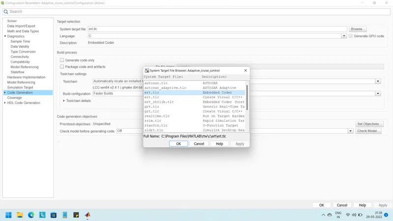
*MODEL ADVISOR
Check the model advisor and in that check MAAB and JMAAB rules .open model advisor and select the checks.
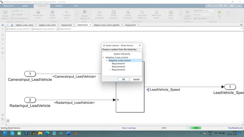
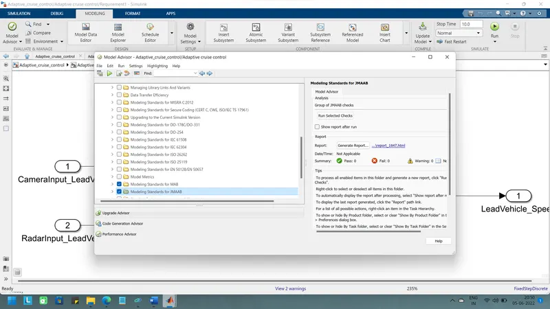
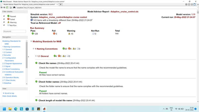
After run the checks report is generated
Code is shown below
Adaptive_cruise_control.c
/*

 * File: Adaptive_cruise_control.c

 *

 * Code generated for Simulink model 'Adaptive_cruise_control'.

 *

 * Model version                  : 1.6

 * Simulink Coder version         : 9.5 (R2021a) 14-Nov-2020

 * C/C++ source code generated on : Sat May 28 21:12:17 2022

 *

 * Target selection: ert.tlc

 * Embedded hardware selection: Intel->x86-64 (Windows64)

 * Code generation objectives: Unspecified

 * Validation result: Not run

 */


#include "Adaptive_cruise_control.h"

#include "Adaptive_cruise_control_private.h"


/* Named constants for Chart: '/Adaptive _Cruise _Control _Algorithm' */

#define Ada_IN_LeadVehicle_Not_Detected ((uint8_T)3U)

#define Adaptive_cr_IN_ACC_STANDBY_MODE ((uint8_T)3U)

#define Adaptive_cru_IN_NO_ACTIVE_CHILD ((uint8_T)0U)

#define Adaptive_cruise_IN_ACC_OFF_MODE ((uint8_T)1U)

#define Adaptive_cruise__IN_ACC_ON_MODE ((uint8_T)2U)

#define IN_LeadVehicle_Detected_Follow ((uint8_T)1U)

#define IN_LeadVehicle_Detected_Resume ((uint8_T)2U)

#define IN_LeadVehicle_Not_Detected_Res ((uint8_T)4U)

#define IN_LeadVehicle_Speed_equal_Set_ ((uint8_T)5U)

#define IN_LeadVehicle_Speed_lessthan_S ((uint8_T)6U)


/* Block states (default storage) */

DW_Adaptive_cruise_control_T Adaptive_cruise_control_DW;


/* External outputs (root outports fed by signals with default storage) */

ExtY_Adaptive_cruise_control_T Adaptive_cruise_control_Y;


/* Real-time model */

static RT_MODEL_Adaptive_cruise_cont_T Adaptive_cruise_control_M_;

RT_MODEL_Adaptive_cruise_cont_T *const Adaptive_cruise_control_M =

  &Adaptive_cruise_control_M_;

real_T rt_roundd_snf(real_T u)

{

  real_T y;

  if (fabs(u) < 4.503599627370496E+15) {

    if (u >= 0.5) {

      y = floor(u + 0.5);

    } else if (u > -0.5) {

      y = u * 0.0;

    } else {

      y = ceil(u - 0.5);

    }

  } else {

    y = u;

  }


  return y;

}


/* Model step function */

void Adaptive_cruise_control_step(void)

{

  real_T rtb_DriveVehicle_Speed;

  int32_T tmp;

  int32_T tmp_0;

  uint8_T rtb_LeadVehicle_Speed;

  uint8_T tmp_1;

  uint8_T tmp_2;


  /* Sum: '/Add' incorporates:

   *  Inport: '/CameraInput_LeadVehicle'

   *  Inport: '/RadarInput_LeadVehicle'

   */

  rtb_LeadVehicle_Speed = (uint8_T)((uint32_T)CameraInput_LeadVehicle +

    RadarInput_LeadVehicle);


  /* Sum: '/Add' incorporates:

   *  Inport: '/CameraInput_DriveVehicle  '

   *  Inport: '/RadarInput_DriveVehicle'

   *  UnitDelay: '/Unit Delay'

   */

  rtb_DriveVehicle_Speed = ((real_T)CameraInput_DriveVehicle +

    Adaptive_cruise_control_Y.Acceleration_Mode) + (real_T)

    RadarInput_DriveVehicle;


  /* Chart: '/Adaptive _Cruise _Control _Algorithm' incorporates:

   *  Inport: '/CruiseSwitch'

   *  Inport: '/RadarInput_DriveVehicle'

   *  Inport: '/SetSwitch'

   *  Inport: '/Set_Gap'

   *  Inport: '/Set_Speed'

   *  Inport: '/Time_Gap'

   *  UnitDelay: '/Unit Delay'

   */

  if (Adaptive_cruise_control_DW.is_active_c3_Adaptive_cruise_co == 0U) {

    Adaptive_cruise_control_DW.is_active_c3_Adaptive_cruise_co = 1U;

    Adaptive_cruise_control_DW.is_c3_Adaptive_cruise_control =

      Adaptive_cruise_IN_ACC_OFF_MODE;

    Adaptive_cruise_control_Y.Acceleration_Mode = 0.0;

  } else {

    switch (Adaptive_cruise_control_DW.is_c3_Adaptive_cruise_control) {

     case Adaptive_cruise_IN_ACC_OFF_MODE:

      Adaptive_cruise_control_Y.Acceleration_Mode = 0.0;

      if (CruiseSwitch) {

        Adaptive_cruise_control_DW.is_c3_Adaptive_cruise_control =

          Adaptive_cr_IN_ACC_STANDBY_MODE;

        Adaptive_cruise_control_Y.Acceleration_Mode = 1.0;

      }

      break;


     case Adaptive_cruise__IN_ACC_ON_MODE:

      if (SetSwitch) {

        Adaptive_cruise_control_DW.is_ACC_ON_MODE =

          Adaptive_cru_IN_NO_ACTIVE_CHILD;

        Adaptive_cruise_control_DW.is_c3_Adaptive_cruise_control =

          Adaptive_cr_IN_ACC_STANDBY_MODE;

        Adaptive_cruise_control_Y.Acceleration_Mode = 1.0;

      } else if (!CruiseSwitch) {

        Adaptive_cruise_control_DW.is_ACC_ON_MODE =

          Adaptive_cru_IN_NO_ACTIVE_CHILD;

        Adaptive_cruise_control_DW.is_c3_Adaptive_cruise_control =

          Adaptive_cruise_IN_ACC_OFF_MODE;

        Adaptive_cruise_control_Y.Acceleration_Mode = 0.0;

      } else {

        switch (Adaptive_cruise_control_DW.is_ACC_ON_MODE) {

         case IN_LeadVehicle_Detected_Follow:

          Adaptive_cruise_control_Y.Acceleration_Mode = 2.0;

          if (RadarInput_DriveVehicle == 0) {

            Adaptive_cruise_control_DW.is_ACC_ON_MODE =

              Ada_IN_LeadVehicle_Not_Detected;

            Adaptive_cruise_control_Y.Acceleration_Mode = 1.0;

          } else if (((RadarInput_DriveVehicle == 1) && (rtb_LeadVehicle_Speed <

            Set_Speed)) || (Time_Gap < Set_Gap)) {

            Adaptive_cruise_control_DW.is_ACC_ON_MODE =

              IN_LeadVehicle_Speed_lessthan_S;

            Adaptive_cruise_control_Y.Acceleration_Mode = 4.0;

          }

          break;


         case IN_LeadVehicle_Detected_Resume:

          Adaptive_cruise_control_Y.Acceleration_Mode = 3.0;

          if ((rtb_DriveVehicle_Speed == Set_Speed) && (rtb_LeadVehicle_Speed >=

               Set_Speed) && (Time_Gap >= Set_Gap)) {

            Adaptive_cruise_control_DW.is_ACC_ON_MODE =

              IN_LeadVehicle_Detected_Follow;

            Adaptive_cruise_control_Y.Acceleration_Mode = 2.0;

          } else if ((rtb_DriveVehicle_Speed < Set_Speed) &&

                     (rtb_LeadVehicle_Speed > rtb_DriveVehicle_Speed) &&

                     (Time_Gap >= Set_Gap)) {

            Adaptive_cruise_control_DW.is_ACC_ON_MODE =

              IN_LeadVehicle_Speed_equal_Set_;

            Adaptive_cruise_control_Y.Acceleration_Mode = 5.0;

          } else if (RadarInput_DriveVehicle == 0) {

            Adaptive_cruise_control_DW.is_ACC_ON_MODE =

              IN_LeadVehicle_Not_Detected_Res;

            Adaptive_cruise_control_Y.Acceleration_Mode = 1.0;

          }

          break;


         case Ada_IN_LeadVehicle_Not_Detected:

          Adaptive_cruise_control_Y.Acceleration_Mode = 1.0;

          if ((RadarInput_DriveVehicle == 1) && (rtb_DriveVehicle_Speed ==

               Set_Speed) && (rtb_LeadVehicle_Speed >= Set_Speed) && (Time_Gap >=

               Set_Gap)) {

            Adaptive_cruise_control_DW.is_ACC_ON_MODE =

              IN_LeadVehicle_Detected_Follow;

            Adaptive_cruise_control_Y.Acceleration_Mode = 2.0;

          } else if (((RadarInput_DriveVehicle == 1) && (rtb_LeadVehicle_Speed <

            Set_Speed)) || (Time_Gap < Set_Gap)) {

            Adaptive_cruise_control_DW.is_ACC_ON_MODE =

              IN_LeadVehicle_Speed_lessthan_S;

            Adaptive_cruise_control_Y.Acceleration_Mode = 4.0;

          }

          break;


         case IN_LeadVehicle_Not_Detected_Res:

          Adaptive_cruise_control_Y.Acceleration_Mode = 1.0;

          break;


         case IN_LeadVehicle_Speed_equal_Set_:

          Adaptive_cruise_control_Y.Acceleration_Mode = 5.0;

          if ((RadarInput_DriveVehicle == 0) || (rtb_DriveVehicle_Speed <=

               Set_Speed)) {

            Adaptive_cruise_control_DW.is_ACC_ON_MODE =

              IN_LeadVehicle_Not_Detected_Res;

            Adaptive_cruise_control_Y.Acceleration_Mode = 1.0;

          } else if (((rtb_DriveVehicle_Speed < Set_Speed) &&

                      (rtb_LeadVehicle_Speed > rtb_DriveVehicle_Speed)) ||

                     (Time_Gap >= Set_Gap)) {

            Adaptive_cruise_control_DW.is_ACC_ON_MODE =

              IN_LeadVehicle_Detected_Resume;

            Adaptive_cruise_control_Y.Acceleration_Mode = 3.0;

          } else if (((rtb_LeadVehicle_Speed < Set_Speed) &&

                      (rtb_LeadVehicle_Speed < rtb_DriveVehicle_Speed)) ||

                     ((int32_T)rt_roundd_snf(0.75 * (real_T)Set_Gap) == Time_Gap))

          {

            Adaptive_cruise_control_DW.is_ACC_ON_MODE =

              IN_LeadVehicle_Speed_lessthan_S;

            Adaptive_cruise_control_Y.Acceleration_Mode = 4.0;

          }

          break;


         default:

          /* case IN_LeadVehicle_Speed_lessthan_Set_Speed: */

          Adaptive_cruise_control_Y.Acceleration_Mode = 4.0;

          if ((RadarInput_DriveVehicle == 0) && (rtb_DriveVehicle_Speed ==

               Set_Speed)) {

            Adaptive_cruise_control_DW.is_ACC_ON_MODE =

              Ada_IN_LeadVehicle_Not_Detected;

            Adaptive_cruise_control_Y.Acceleration_Mode = 1.0;

          } else {

            tmp = (int32_T)rt_roundd_snf((real_T)rtb_LeadVehicle_Speed * 1.25);

            tmp_0 = (int32_T)rt_roundd_snf(1.25 * (real_T)Set_Gap);

            if (tmp < 256) {

              tmp_1 = (uint8_T)tmp;

            } else {

              tmp_1 = MAX_uint8_T;

            }


            if (tmp_0 < 256) {

              tmp_2 = (uint8_T)tmp_0;

            } else {

              tmp_2 = MAX_uint8_T;

            }


            if ((tmp_1 >= rtb_DriveVehicle_Speed) && (rt_roundd_snf((real_T)

                  rtb_LeadVehicle_Speed * 0.75) <= rtb_DriveVehicle_Speed) &&

                (rtb_DriveVehicle_Speed < Set_Speed) && (Time_Gap <= tmp_2) &&

                (Time_Gap >= (int32_T)rt_roundd_snf(0.75 * (real_T)Set_Gap))) {

              Adaptive_cruise_control_DW.is_ACC_ON_MODE =

                IN_LeadVehicle_Speed_equal_Set_;

              Adaptive_cruise_control_Y.Acceleration_Mode = 5.0;

            }

          }

          break;

        }

      }

      break;


     default:

      /* case IN_ACC_STANDBY_MODE: */

      Adaptive_cruise_control_Y.Acceleration_Mode = 1.0;

      if (!CruiseSwitch) {

        Adaptive_cruise_control_DW.is_c3_Adaptive_cruise_control =

          Adaptive_cruise_IN_ACC_OFF_MODE;

        Adaptive_cruise_control_Y.Acceleration_Mode = 0.0;

      } else if (!SetSwitch) {

        Adaptive_cruise_control_DW.is_c3_Adaptive_cruise_control =

          Adaptive_cruise__IN_ACC_ON_MODE;

        Adaptive_cruise_control_DW.is_ACC_ON_MODE =

          IN_LeadVehicle_Detected_Follow;

        Adaptive_cruise_control_Y.Acceleration_Mode = 2.0;

      }

      break;

    }

  }


  /* End of Chart: '/Adaptive _Cruise _Control _Algorithm' */

}


/* Model initialize function */

void Adaptive_cruise_control_initialize(void)

{

  /* (no initialization code required) */

}


/* Model terminate function */

void Adaptive_cruise_control_terminate(void)

{

  /* (no terminate code required) */

}


/*

 * File trailer for generated code.

 *

 * [EOF]

 */
Conclusion:
Thus, a Simulink model for Adaptive Cruise Control has been designed and a Simulink data dictionary file has been created along with the code generation of the created model and its model advisor report satisfactorily.