Project-1: Powertrain for aircraft in runways
1.
An aircraft's gross weight will decrease during a flight when fuel and oil is being consumed. Gross weight may also vary during a flight due to payload dropping or in flight refueling. At the time of releasing its brakes, the gross weight of an aircraft is equal to its takeoff weight. During flight, an it's gross weight is referred to as the en-route weight or in-flight weight. An aircraft's gross weight is limited by several weight restriction. To avoid overloading its structure or to avoid unacceptable performance or handling qualities while in operation aircraft gross weight limits are established during an aircraft's design and certification period.
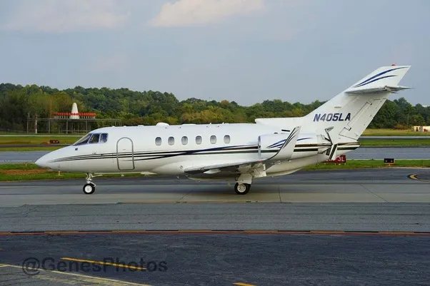
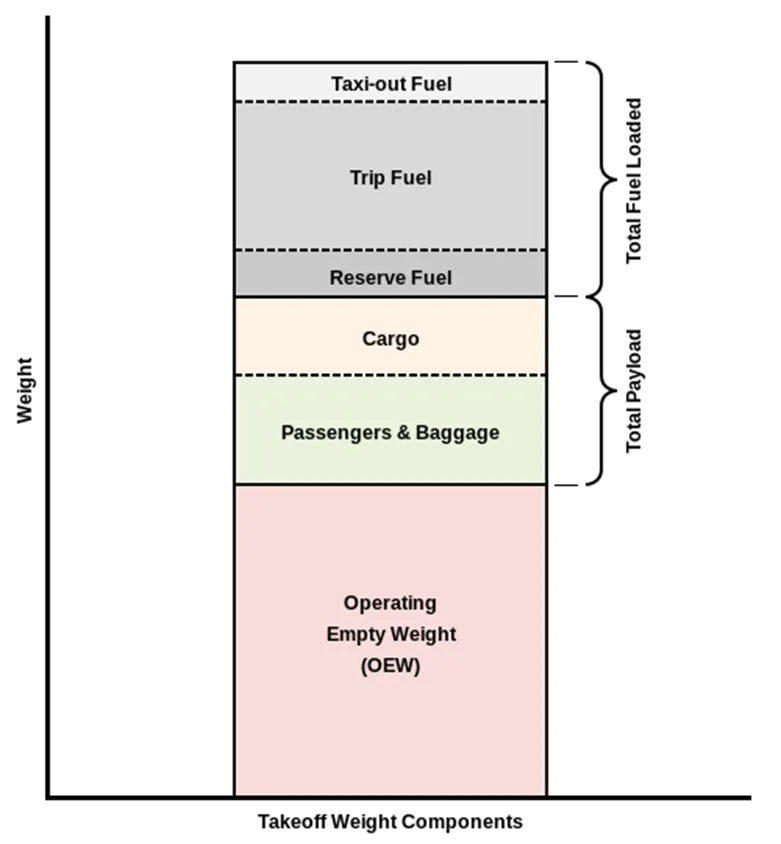
Manufacturer’s empty weight (MEW)
It is the weight of the aircraft "as built" and includes the weight of the structure, power plant, furnishings, installations, systems and other equipment that are considered an integral part of an aircraft.
Zero-fuel weight (ZFW)
This is the total weight of the airplane and all its contents (including unusable fuel), but excluding the total weight of the usable fuel on board.
As a flight progresses and fuel is consumed, the total weight of the airplane reduces, but the ZFW remains constant.
Maximum zero fuel weight (MZFW) is the maximum weight allowed before usable fuel and other specified usable agents (engine injection fluid, and other consumable propulsion agents) are loaded.
Operating empty weight (OEW) (Roughly equivalent to basic empty weight on light aircraft)
It is the basic weight of an aircraft including the crew, all fluids necessary for operation such as engine oil, engine coolant, water, unusable fuel and all operator items and equipment required for flight but excluding usable fuel and the payload.
Payload
It is the carrying capacity of an aircraft. It includes cargo, people, extra fuel. In the case of a commercial airliner, it may refer only to revenue-generating cargo or paying passengers.
Maximum takeoff weight (MTOW)
This is the maximum weight at which the pilot of the aircraft is allowed to attempt to take off
Regulated takeoff weight (RTOW)
Depending on different factors (e.g. flap setting, altitude, air temperature, length of runway), RTOW or maximum permissible takeoff weight varies for each takeoff. It can never be higher than MTOW.
Maximum ramp weight (MRW)
also called maximum taxi weight (MTW)
It is the maximum weight authorized for maneuvering (taxiing or towing) an aircraft on the ground.
Aircraft gross weight
It is the total aircraft weight at any moment during the flight or ground operation. This decreases during flight due to fuel and oil consumption.
Typical Airplane Weights
Below is a table of some of the most common aircraft flying around our skies today:
|
Aircraft |
Empty Weight |
Max Fuel Weight |
Max Cargo Weight |
Max Gross Takeoff Weight |
|
Antanov AN-225 |
628,000 lbs |
661,400 lbs |
417,000 lbs |
1,411,000 lbs |
|
Airbus A380-800 |
611,000 lbs |
560,000 lbs |
185,000 lbs |
1,268,000 lbs |
|
Boeing 747-800 |
485,300 lbs |
427,400 lbs |
295,000 lbs |
987,000 lbs |
|
Airbus A340-500 |
370,000 lbs |
386,300 lbs |
119,000 lbs |
820,000 lbs |
|
Boeing 777-300ER |
370,000 lbs 168,000 kg |
320,800 lbs 145,500 kg |
148,000 lbs |
776,000 lbs |
|
Boeing 787-10 |
299,000 lbs 135,500 kg |
223,500 lbs |
126,300 lbs 57,300 kg |
560,000 lbs |
|
Boeing 737-900 |
98,500 lbs |
53,100 lbs |
44,600 lbs |
187,000 lbs |
|
Airbus A320-100 |
93,900 lbs |
48,700 lbs |
44,000 lbs |
150,000 lbs |
|
Embraer 190 |
63,500 lbs |
28,600 lbs |
28,800 lbs |
106,000 lbs |
|
Gulfstream G650 |
54,000 lbs 24,500 kg |
48,200 lbs 21,900 kg |
6,500 lbs |
100,000 lbs |
|
Bombardier CRJ900 |
48,160 lbs 21,850 kg |
19,600 lbs 8,900 kg |
6,075 lbs 2,760 kg |
80,500 lbs |
|
Bombardier Q400 |
39,300 lbs |
11,700 lbs |
18,700 lbs |
62,000 lbs |
|
Learjet 75 |
13,900 lbs 6,300 kg |
6,060 lbs |
2,900 lbs |
21,500 lbs |
|
Cessna Citation CJ4 |
10,300 lbs 4,700 kg |
5,800 lbs |
2,200 lbs 1,000 kg |
17,200 lbs |
|
Beechcraft King Air B100 |
7,100 lbs 3,200 kg |
3,200 lbs |
4,150 lbs |
12,000 lbs |
|
Diamond DA50 RG |
3,200 lbs |
340 lbs |
1,250 lbs |
4,400 lbs |
|
Beechcraft Bonanza G36 |
2,500 lbs 1,150 kg |
450 lbs |
850 lbs |
3,660 lbs |
|
Cessna 206H |
2,200 lbs |
520 lbs |
1,150 lbs |
3,600 lbs |
|
Sirrus SR22 |
2,250 lbs 1,000 kg |
485 lbs |
950 lbs |
3,600 lbs |
|
Cessna 172R |
1,700 lbs |
380 lbs |
560 lbs |
2,425 lbs |
2.Is there any difference between ground speed and air speed.
Airspeed vs. Ground Speed
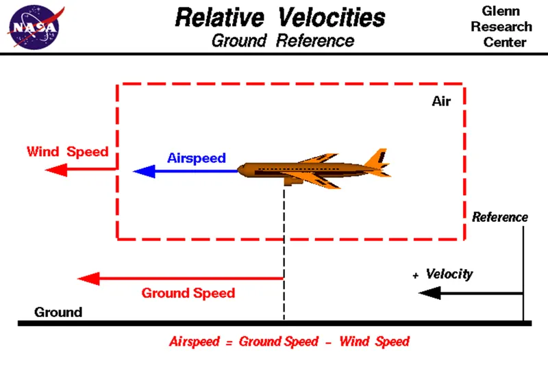
True airspeed is simply the speed at which an aircraft is moving relative to the air it is flying in. As such, it’s also the speed at which the air is flowing around the aircraft’s wings.
Ground speed, on the other hand, is the aircraft’s speed relative to the ground. One thing that should be noted here is that it’s its horizontal rather than vertical speed – an aircraft climbing completely vertically would have a ground speed of zero.
In other words, while airspeed is what determines whether there is enough airflow around an aircraft to make it fly, ground speed is what determines how fast an aircraft will get to its destination.
When I talked about airspeed earlier in this article, I was talking about true airspeed. However, pilots commonly use three different types of airspeed: indicated airspeed, calibrated airspeed, and true airspeed.
Indicated airspeed is an airspeed that is calculated directly off an aircraft’s pitot-static system. It’s the calculated off the aircraft’s dynamic pressure – the difference between its total pressure and static pressure.
The dynamic pressure depends not only on the aircraft’s speed, but also on the density of the air it is flying in. As such, the higher the aircraft flies – and the lower the air density as a result – the bigger the difference between indicated and true airspeed is.
Calibrated airspeed is indicated airspeed adjusted for a variety of errors.
Just as an example, one of the things it’s adjusted for is the flap position. The reason for that is that at different flap positions, air flows differently around the pitot-static system and affects the indicated airspeed readings.
True airspeed is, as has been mentioned numerous times in this article, the actual speed at which an aircraft is moving relative to the air it is traveling in. It’s calibrated airspeed adjusted for the the exact conditions (altitude, air temperature, etc.) that the aircraft is flying in.
3. Why is it not recommended to use aircraft engine power to move it on the ground at Airport.
For movement on the ground the aircraft uses it own engine power, which is called taxing.
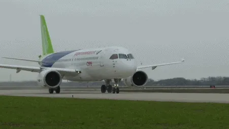
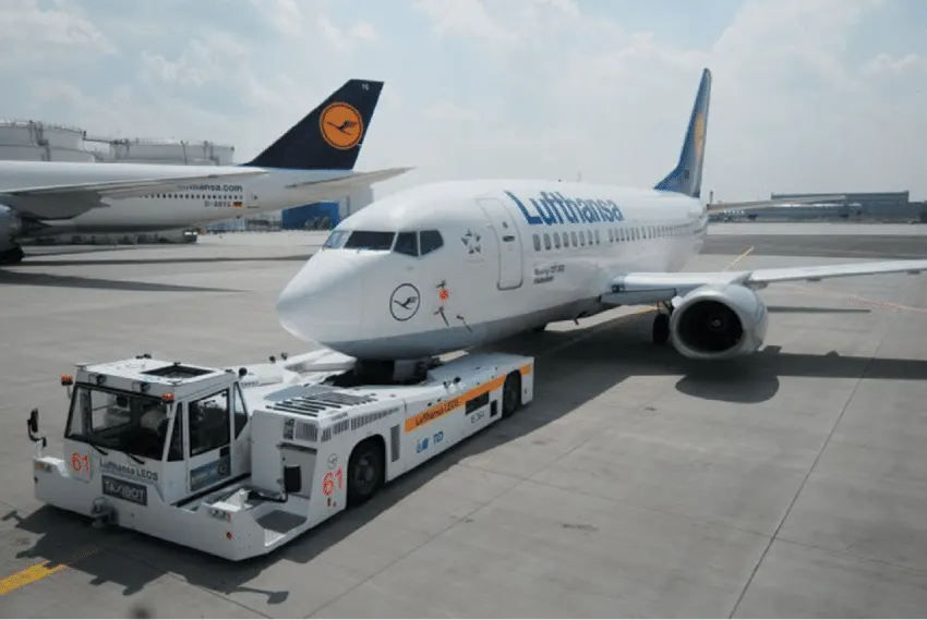
Although many aircrafts are capable of moving in backward using reverse thrust, as result the jet blast or prop wash might cause damage to the terminal building or equipment. Engine close to ground may also blow sand and debris forward and then suck them into the engine, causing damage to the engine. Therefore there are pushback trucks in the airport. A pushback truck lifts the front weel of the aircraft, their role in most airports is to move the aircraft away from the parking spot on to the taxiways, which is called towing.
Q_4 How an aircraft is pushed to runway when its ready to take off.
Pushback means the movement of an aircraft from a nose-in parking stand using the power of a specialised ground vehicle attached to or supporting the nose landing gear. It is commonly the second part of a ‘Taxi In Push Out’ (TIPO) procedure at airport terminal gates and will be necessary to depart from all except self manoeuvring parking stands unless the aircraft type is capable of powerback and local procedures allow this. Occasionally, a pushback may need to be followed by an engines-running pull forward to a position where local procedures allow aircraft to move forward under their own power, but usually, ground vehicle disconnection will occur after the completion of a pushback.
The Procedure
Once the aircraft commander (or other person in charge on the flight deck if the aircraft is not in service) has given their confirmation of ‘brakes released’ to the person in charge of the ground crew who are to carry out the pushback, the ground crew become temporarily responsible for the safe manoeuvring of the aircraft in accordance with either promulgated standard procedures or as specifically agreed beforehand.
Unless the manoeuvre is taking place outside the movement area controlled by ATC, an RTF clearance to carry it out will be required. Usually but not always, this will be obtained by the aircraft commander or other person in charge in the flight deck. The prescribed RTF phraseology for pushback is contained in ICAO PANS-ATM.
Formerly, almost all aircraft types required that the ground locking pin be installed in the nose landing gear during any pushback; however, this is now no longer always the case. If a ground locking pin is installed for the pushback, it will need to be removed after the completion of the ground vehicle manoeuvre if the aircraft has been pushed back prior to intended flight.
The ‘traditional’ method of allowing the ground vehicle to move an aircraft is to attach it to the aircraft nose landing gear by means of a towbar. These must be approved for use with a particular aircraft type and clearly marked as such, since there is no universal towbar specification. The same towbar attachment and ground vehicle may also be used for Aircraft Towing in the forward direction. An alternative method which is becoming more common for pushback is the use of a specialised vehicle called a ‘towbarless tug’. This positions two low level ‘arms’ either side of the aircraft nose landing gear and these are used to engage with the aircraft gear leg and raise it slightly off the ground. These specialised vehicles can also be used to tow aircraft forward,
Both pushback methods are subject to the observance of any aircraft limits for maximum nose landing gear steering angle, but these are not usually especially restrictive.
The responsibilities of the ground crew team carrying out a pushback include ensuring that no part of the aircraft structure will impact any fixed object or other aircraft and may include giving clearance to start one or more engines just before, during or immediately after a pushback. The number of people assigned to a ground crew team for a pushback may vary according to aircraft size, but in most cases will be at least three. One will be driving the pushback vehicle, one will be walking in the vicinity of one of the aircraft wingtips and looking beyond the aircraft tail and one will be in charge of the manoeuvre and in communication with the person with aircraft responsibility in the flight deck. Communication between the ground crew supervisor is usually by means of a plug in to an aircraft ground intercom circuit; if so, this is facilitated by a ground crew microphone which acquires the voice of the user whilst excluding background noise, which if the aircraft engines are running can be considerable. If only two ground crew are used for pushback of a smaller aircraft then it is important that the procedure takes full account of the roles of each ground crewmember and that the person in charge of ground crew communications on the flight deck is aware of the number of ground crew being used and the physical location of the supervisor.
Effective communication between the person in charge in the flight deck and the person in charge of the ground crew, and between the members of the ground crew team is critical. If the aircraft is being pushed back prior to intended flight and the person in charge of the flight deck is therefore an aircraft commander, the procedures of the aircraft operator may require that the designatedPilot Flying, who may be the co pilot, should oversee the pushback and in this case all communications with the ground crew will be undertaken by that person rather than necessarily by the aircraft commander. If it is considered that communication by hand signals rather than intercom is acceptable then it is essential that the applicable procedures are comprehensive and thoroughly understood by both parties and that they cover all possible abnormal and emergency circumstances.
The case of engines-running pull forward as a supplementary action prior to ground vehicle disconnection after a pushback should be considered as part of the pushback procedure and trained accordingly since it bears little practical resemblance to the towing for longer distances of empty out-of-service with engines stopped.
Engine Starts may be routinely accomplished immediately before or during pushback. Where they are carried out when the aircraft is moving, it is essential that the ground crew supervisor does not allow the checks and communication required in connection with engine starting to interfere with their primary responsibility to control the pushback and remain in full communication with those on the flight deck using the means available. Many aircraft operators require that when push back is accomplished without headset communications, engine starts do not take place whilst the aircraft is being pushed, preferring instead to require that engine starting takes place before or after completion of the pushback. Observations of abnormal circumstances in connection with engine starts or any other matter affecting, or potentially affecting the safety of the aircraft during a pushback are of great importance to those on the flight deck but it is essential that any descriptions of external observations during engine starts are imparted accurately; this may sometimes be demanding using ground intercom but can be extremely difficult with only hand signals available.
- The pilot parks the aircraft in exactly the right place. Usually with the help of an automatic system, but occasionally guided by a marshaller waving two paddles or wands. Dozens of handling personnel are already standing by to perform a whole range of tasks simultaneously.
- As soon as the aircraft is stationary and the engines are switched off, the first priority is to disembark the passengers as quickly as possible. The apron handler places chocks in front of the wheels and connects the ground power. Meanwhile, the passenger bridge manoeuvres up to the door and a belt loader rolls up to the cargo hold. Luggage is unloaded and transferred to the terminal on baggage carts.
- Refuelling begins, usually from a hydrant at the stand. A hose is attached to this from a special vehicle called a dispenser, with the other side connected to the fuel tank in the wing.
- Now it is time to service the aircraft. The caterer loads new meals and takes away the food waste and used cutlery and crockery. Other activities include draining the lavatories, replacing the headrest covers, removing rubbish and distributing fresh blankets and in-flight magazine.
- A specialist team – or sometimes the crew themselves – cleans the cabin so that the new passengers board a pristine aircraft.
- Meanwhile, specialists from the airline conduct a technical check to make sure that the engines, wings, control surfaces, landing gear, instruments, doors and other equipment are in full working order.
- The aircraft is now ready for baggage to be loaded for the next flight. This is a quick process, on average taking only 10-15 minutes. A little later the passengers start boarding. As soon as they are all in their seats, the door is closed and the pilot informs air-traffic control that the flight is ready for departure.
- The apron handler removes the chocks. A so-called pushback truck reverses the aircraft into taxiing position, pushing it with a towbar attached to the nose-wheel strut. Or, in the most modern versions, by actually lifting the wheel. That speeds up coupling and decoupling.
- The aircraft taxis to the runway to depart at the agreed time.
- The pilot waits for permission to take off from air-traffic control. This is possible once the departure route is clear. As soon as the go-ahead is received, the plane takes to the air at full power.
Taxiing refers to the movement of an aircraft on the ground, under its own power. The aircraft moves on wheels. An airplane uses taxiways to taxi from one place on an airport to another; for example, when moving from a terminal to the runway.
The aircrafts always moves on the ground following the yellow lines, to avoid any collision with the surrounding buildings, vehicles or other aircrafts. The taxiing motion has a speed limit. Before making a turn, the pilot reduces the speed further to prevent tire skids. Just like cars, there is a certain list of priorities during taxiing. The aircrafts that are landing or taking off have higher priority. The other aircrafts have to wait for these aircrafts before they start or continue taxiing.
The thrust to propel the aircraft forward comes from its propellers or jet engines. Steering is achieved by turning a nose wheel or tail wheel/rudder; the pilot controlling the direction travelled with their feet. The use of engine thrust near terminals is restricted due to the possibility of jet blast damage. This is why the aircrafts are pushed back from the buildings by a vehicle before they can start their own engines for taxiing.
Take-Off
Takeoff is the phase of flight in which an aircraft goes through a transition from moving along the ground (taxiing) to flying in the air, usually starting on a runway. Usually the engines are run at full power during takeoff. Following the taxi motion, the aircraft stops at the starting line of the runway. Before takeoff, the engines, particularly piston engines, are routinely run up at high power to check for engine-related problems. This makes a consid- erable noise. When the pilot releases the brakes, the aircraft starts accelerating rapidly until the necessary speed for take-off is achieved.
The takeoff speed required varies with air den- sity, aircraft weight, and aircraft configuration (flap and/or slat position, as applicable). Air density is affected by factors such as field ele- vation and air temperature.
Operations with transport category aircraft employ the concept of the takeoff V-Speeds, V1 and V2. These speeds are determined not only by the above factors affecting takeoff perform- ance, but also by the length and slope of the runway. Below V1, in case of critical failures, the takeoff should be aborted; above V1 the pilot continues the takeoff and returns for land- ing. After the co-pilot calls V1, Then, V2 (the safe takeoff speed) is called. This speed must be maintained after an engine failure to meet per- formance targets for rate of climb and angle of climb.
The speeds needed for takeoff are relative to the motion of the air (indicated airspeed). A head wind will reduce the ground speed needed for takeoff, as there is a greater flow of air over the wings. This is why the aircrafts always take off against the wind. Side wind is not preferred as it would disturb the stability of the aircraft. Typical takeoff air speeds for jetliners are in the 130–155 knot range (150–180 mph, 240–285 km/h). For a given aircraft, the takeoff speed is usually directly proportional to the aircraft weight; the heavier the weight, the greater the speed needed. Some aircraft have difficulty generating enough lift at the low speeds encountered during takeoff. These are therefore fitted with high-lift devices, often including slats and usually flaps, which increase the camber of the wing, making it more effective at low speed, thus creating more lift. These have to be deployed from the wing before performing any maneuver.
At the beginning of the climb phase, the wheels are retracted into the aircraft and the undercarriage doors are closed. This operation is audible by the passengers as a noise coming from below the floor.
Climb
Following take-off, the aircraft has to climb to a certain altitude (typically 30,000 ft or 10 km) before it can cruise at this altitude in a safe and economic way. A climb is carried out by increasing the lift of wings supporting the aircraft until their lifting force exceeds the weight of the aircraft. Once this occurs, the aircraft will climb to a higher altitude until the lifting force and weight are again in balance. The increase in lift may be accomplished by increasing the angle of attack of the wings, by increasing the thrust of the engines to increase speed (thereby increasing lift), by increasing the surface area or shape of the wing to produce greater lift, or by some combination of these techniques. In most cases, engine thrust and angle of attack are simultaneously increased to produce a climb.
Because lift diminishes with decreasing air density, a climb, once initiated, will end by itself when the diminishing lift with increasing altitude drops to a point that equals the weight of the aircraft. At that point, the aircraft will return to level flight at a constant altitude. During climb phase, it is normal that the engine noise diminishes. This is because the engines are operated at a lower power level after the take-off. It is also possible to hear a whirring noise or a change in the tone of the noise during climb. This is the sound of the flaps that are retracting. A wing with retracted flap produces less noise.
Cruise
Cruise is the level portion of aircraft travel where flight is most fuel efficient. It occurs between ascent and descent phases and is usually the majority of a journey. Technically, cruising consists of heading (direction of flight) changes only at a constant airspeed and altitude. It ends as the aircraft approaches the destination where the descent phase of flight commences in preparation for landing.
For most commercial passenger aircraft, the cruise phase of flight consumes the majority of fuel. As this lightens the aircraft considerably, higher altitudes are more efficient for additional fuel economy. However, for operational and air traffic control reasons it is necessary to stay at the cleared flight level. Typical cruising speed for long-distance commercial passenger flights is 475-500 knots (878-926 km/h; 547-578 mph).
Commercial or passenger aircraft are usually designed for optimum performance at their cruise speed. There is also an optimum cruise altitude for a particular aircraft type and conditions including payload weight, center of gravity, air temperature, humidity, and speed. This altitude is usually where the drag is minimum and the lift is maximum. As in any phase of the flight, the aircraft in cruise mode is always in communication with an Air Traffic Control (ATC) station. Although the general tendency is to follow a straight line towards the destination, there may be some deviations from the flight plan for weather, turbulence or air traffic rea- sons, after receiving clearance from ATC.
Descent
A descent during air travel is any portion where an aircraft decreases altitude. Descents are an essential component of an approach to landing. Other partial descents might be to avoid traffic, poor flight conditions (turbulence or bad weather), clouds (particularly under visual flight rules), to see something lower, to enter warmer air (in the case of extreme cold), or to take advantage of wind direction of a different altitude. Normal descents take place at a con- stant airspeed and constant angle of descent (3 degree final approach at most airports). The pilot controls the angle of descent by varying engine power and pitch angle (lowering the nose) to keep the airspeed constant.
At the beginning of and during the descent phase, the engine noise diminishes further as the engines are operated at low power settings. However, towards the end of the descent phase, the passenger can feel further accelerations and an increase in the noise. This is to realize the “final approach” before taking “landing posi- tion”.
Landing
Landing is the last part of a flight, where the aircraft returns to the ground. Aircraft usually land at an airport on a firm runway, generally constructed of asphalt concrete, concrete, gravel or grass. To land, the airspeed and the rate of descent are reduced to where the object descends at a slow enough rate to allow for a gentle touch down. Landing is accomplished by slowing down and descending to the runway. This speed reduction is accomplished by reducing thrust and/or inducing a greater amount of drag using flaps, landing gear or speed brakes. As the plane approaches the ground, the pilot will execute a flare (roundout) to induce a gentle landing. Although the pilots are trained to perform the landing operation, there are “Instrument Landing Systems” in most of the airports to help pilots land the aircrafts. An instrument landing system (ILS) is a ground-based instrument approach system that provides precision guid- ance to an aircraft approaching and landing on a runway, using a combination of radio signals and, in many cases, high-intensity lighting arrays to enable a safe landing during instrument meteorological conditions (IMC), such as low ceilings or reduced visibility due to fog, rain, or blowing snow.
At the beginning of the landing phase, the pas- sengers will hear the opening of the doors of the landing gears. As the landing gears are deployed, they will create an additional drag and an additional noise. Immediately after touch-down, the passengers can hear a blowing sound, sometimes with increasing engine sound. This is the engine’s thrust reverses, helping the aircraft to slow down to taxi speeds by redirecting the airflow of the engines for- ward. Once the aircraft is decelerated to low speed, it can taxi to the terminal building.
Q_5 Learn about take off power, tyre design, rolling resistance, tyre pressure, brake forces when landing.
Takeoff power
The amount of power that an engine is allowed to produce for a limited period of time for takeoff. The use of takeoff power is usually limited to 5 min for reciprocating engines and up to 2½ min for gas turbine engines. This may not always be the case. Specifically, with respect to reciprocating engines, it is the brake horsepower developed under standard, sea-level conditions and under the maximum conditions of the crankshaft rotational speed and the engine manifold pressure approved for the normal take-off. It is limited in continuous use to the period of time shown in the approved engine specifications. With respect to gas turbine engines, it is the thrust developed under static conditions at a specified altitude and atmospheric conditions of the rotor shaft rotational speed and gas temperature approved for the normal takeoff. It is limited in continuous use to the period of time shown in the approved engine specifications.
Many aviation technicians are not aware of the critical design factors of aircraft tyre in use today. I will discuss step by step, but first, I would like to ask the importance of tyre in aircraft.
Tyre Design:
When it comes to safety tyres are one of the most important components of aircraft. They help to absorb the shock of landing and provide cushioning. It also provides the necessary traction for braking and stopping of an aircraft.
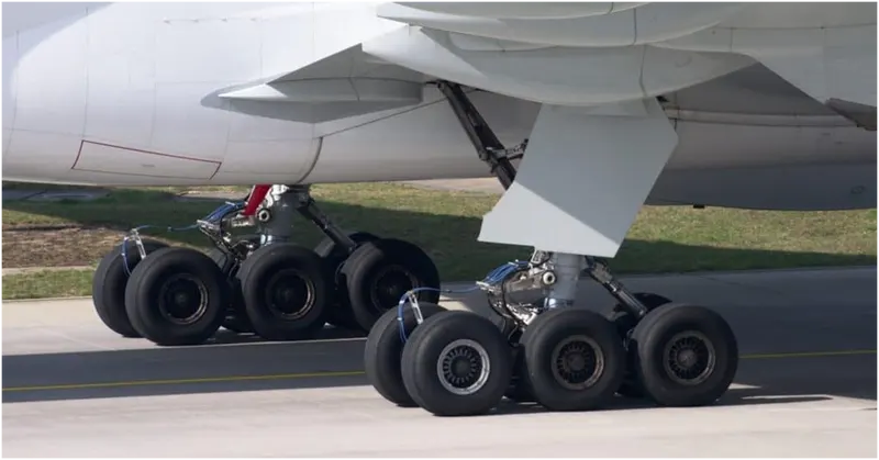
An aircraft tyre is designed to withstand extremely heavy loads while landing, take off, taxing, and parking. The number of wheels required for aircraft increases with the weight of the aircraft, as the weight of the aeroplane needs to be distributed more evenly.
A Boeing 737NG & 737MAX uses 6 wheels, Boeing 787 uses 10 wheels, Boeing 777 uses 14 wheels and Airbus A380 uses 22 wheels. Aircraft tyres work under extreme conditions, carrying up to 340 tons and accelerating at over 250 km/hour at takeoff, in addition to enduring varied environmental stress when in flight and taxiing.
Design and Construction of Aircraft tyre
Carcass plies are used to form the tire. They are sometimes called casing plies. An aircraft tyre is constructed for the purpose it serves.
- They support the weight of an aircraft while it is on the ground.
- It also provides the necessary traction for braking and stopping of an aeroplane.
- Tyre also helps to absorb the shock of landing and provide cushioning the roughness of takeoff, roll-out, and taxi operations.
Unlike an automobile or truck tyre, it does not have to carry a load for a long period of continuous operation. However, an aircraft tyre absorbs the high impact loads of landing, and also it’s operating at high speeds for a short time when required.
Retreading – Retreading is methods of restoring a worn tyre by renewing the tread area or by renewing the tread area plus one or both sidewalls. Repairs are included in the tyre retreading process.
Load Rating – Load rating is the maximum permissible load at a specified inflation pressure.
Ply Rating – Ply Rating is used to identify the maximum recommended load rating and inflation pressure for a specified tyre. It is an index of tyre strength.
Speed Rating – The speed rating is the maximum takeoff speed to which the tyre has been tested.
Skid Depth – Skid depth is the distance between the tread surface and the deepest groove as measured in the mould.
Aircraft tyres must have an approved speed and load rating and have sufficient clearance when retracted through landing gear to allow for tyre growth. Tyre growth is the increase in the size of the tyre due to centrifugal forces at high speed.
Aircraft tyres may be Tube-type or Tubeless
Tubeless tyres are more advantageous over tube-type. There is no longer the use of tube-type tyre in recent aviation. Nowadays all airliners are using tubeless tyres. Tubeless that are meant to be used without a tube has the word TUBELESS on the sidewall of the tyre.
Aircraft tyres may be Radial or Bias
Almost all airliners are using Radial tyre. Bias is an older design, and it’s mainly used for road vehicles. Radial tyres have the word RADIAL on the sidewall. Radial tires are more expensive than bias-ply tyres. Radial tires are in demand because of their lower life cycle cost and long term value.
Yes, Today’s tyres are conductive. Aircraft tyres are manufactured with tread rubber with conducting compounds to permit earthing of static charges.
In early days when tyres were not sufficiently conductive, aircraft used to have a conductive strip hanging down from the axle of the landing gear. Upon landing, this strip would be the first part of the aircraft to touch the earth. This discharges any static electricity accumulated on the outer surfaces of the aircraft. Now you don’t see them anymore.
What is the purpose of Chines in aviation tyre
Chines are also called deflectors. Chine tyre used on the nose wheel of aircraft, specially fuselage-mounted jet engines. It diverts runway water away from the engine inlets.
Chines are circumferential protrusions that are moulded into the sidewall of nose tyres that deflect water sideways to help reduce excess water ingestion into the engines. Tyres may have chines on one or both sides, depending on the number of nose tyres on the aircraft.
Aircraft Tyre Standards
Each tyre manufacturer produces their own designs of the tyre with different tread patterns, wear patterns, wear limits etc, and in some cases, different names for the same part of the tyre. But all tyres must meet the approved standards before being accepted by the FAA or CAA.
All commercial aircraft tyres approved under FAA Requirement Technical Standard Order (TSO) C62. A TSO is a minimum performance standard for specified materials, parts, and appliances used on civil aircraft.
Rolling Resistance
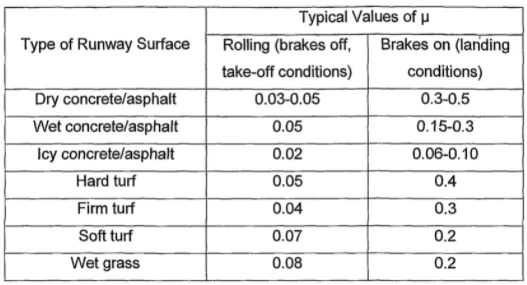
- In addition to the familiar forces like thrust, weight, lift, drag there is a rolling resistance force FR caused by friction between tyre and ground. When aircraft is towing or taxiing to push it into the runway or when takeoff roll is happening, the rolling resistance force act against the traction force of the aircraft.
- This rolling resistance force depends on many factors like surface of the road, roughness of the road, dry or wet condition of the road, tyre pressure, tyre material, tyre temperature, thread pattern of the tyre etc, which determines the rolling resistance force.
- The rolling resistance coefficient is denoted by μrr">μrrμrr. The values vary with speed. Tire pressure increases its value decreases need to carefully choose value as per typical cases under consideration.
Rolling Resistance force (Frr)">(Frr) = μrr">μrrx m x g
Where,
μrr">μrr= Rolling resistance coefficent
m = Total mass of the aircraft in kg
g = Gravitational constant i.e, 9.8 m/s2">s2s2
Tyre Pressure:
Aircraft tires may be tube-type or tubeless. Tubeless tyres are more advantageous over tube-type. There is no longer the use of tube-type tyre in recent aviation. Nowadays all airliners are using tubeless tyres. Tubeless that are meant to be used without a tube has the word TUBELESS on the sidewall of the tyre.
Tyre pressure varies from plane to plane.
- The tires do not use the typical compressed air we would use from a fuel station supply or a home air compressor.
- Aviation tires are made of a much stronger compound than what we use for the auto industry and in fact, they use nitrogen gas to inflate the tires, as opposed to compressed air.
- This provides additional strength to the tires in general, to support the tremendous weight they carry moving the plane or on take-off and for landing.
- The average pressure they run in the tires is between 200-220 PSI, it again depends on the model aircraft(Automobile run 30-40 PSI on average).
- Tires are required to replace after every 300 or so cycles. A cycle represents 1 for a landing and 1 for a lift-off. Every time a plane lands and departs, this is considered 2 cycles.
- When the tire pressure becomes too low then values of rolling resistance increase too much.
Brake forces when landing
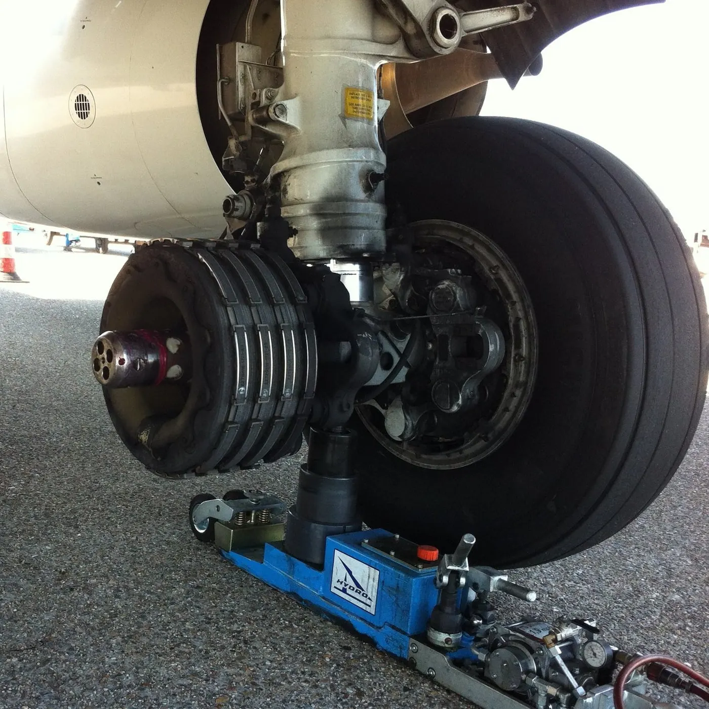
Airplanes rely on a braking system to safely land on runways. At cruising altitude, most commercial airplanes fly at a speed of roughly 500 to 600 mph. When landing, however, they must reduce their speed. A typical 747, for instance, has a landing speed of about 160 to 170 mph. And upon touching the runway, airplanes must quickly brake until they come to a complete stop. How do airplanes brake when landing exactly?
Wing Spoilers
Many airplanes use wing spoilers to assist with braking when landing. Not to be confused with ailerons, spoilers are extendable flaps on the ends of an airplane’s wings. Pilots can raise the spoilers to decelerate the airplane as it approaches the runway. And even while on the runway, pilots will typically leave the wing spoilers raised. Raised wing spoilers create drag, which essentially slows down the airplane so that it’s able to brake more quickly.
Disc Brakes
In addition to wing spoilers, airplanes use disc brakes. Airplane disc brakes are similar to the braking system in automobiles. They consist of a pair of calipers that, when engaged, squeeze pads against the rotors of an airplane’s landing gear.
Disc brakes are designed to remain static at all times. In other words, they don’t rotate with the wheels of an airplane’s landing gear. As the wheels turn, the disc brakes will remain static and stationary. They are a vital component of an airplane’s braking system because they are designed to apply pressure to the airplane’s wheels. Disc brakes will squeeze the wheels, thereby slowing down the speed at which they spin. In turn, this reduces the speed of the airplane so that it can come to a complete stop on the runway.
Reverse Thrust
Finally, many jet airplanes use reverse thrust to assist with braking during landings. Reverse thrust is a feature in jet engine airplanes that, as the name suggests, involves the reversal of the engines’ thrust. When flying, the thrust is projected out the rear of an airplane’s engines. When landing, however, pilots may use the reverse thrust feature. Reverse thrust changes the direction of the engines’ thrust. Rather than projecting out the rear, the thrust will be projected out the front. This reversal of thrust provides deceleration that allows airplanes to slow down more quickly when landing.
Part-B
Q_6(a)
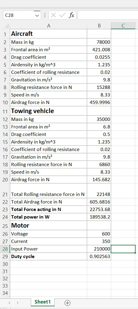
Here to calculate required to push / pull an aircraft by a towing vehicle. the following aircraft model is considered below and its calculations are done
Taking the value of aircraft 320, the specifications are :
Mass : 78000kg
Height : 11.76m
Width : 35.80m
Frontal area(A) : height * width = 11.76 * 35.80
= 421.008m2
Drag coefficient (cd) : 0.0255
Air density (ρ) : 1.235kg/m3
Considering the values of towing vehicle TBL280,
Mass : 35000kg
Height : 2.0m
Width : 3.4m
Frontal area (A) : height * width = 2.0 * 3.4
= 6.8m2
Tyre size (R) : 22’’ = 0.5588m
Drag coefficient (Cd) : 0.5
Air density (ρ) : 1.235kg/ m3
Speed (V) : 30kmph = 30 * 5/18
= 8.33m/s
Now lets calculate the forces acting on the aircraft by towing vehicle
Rolling resistance force ; Air drag force
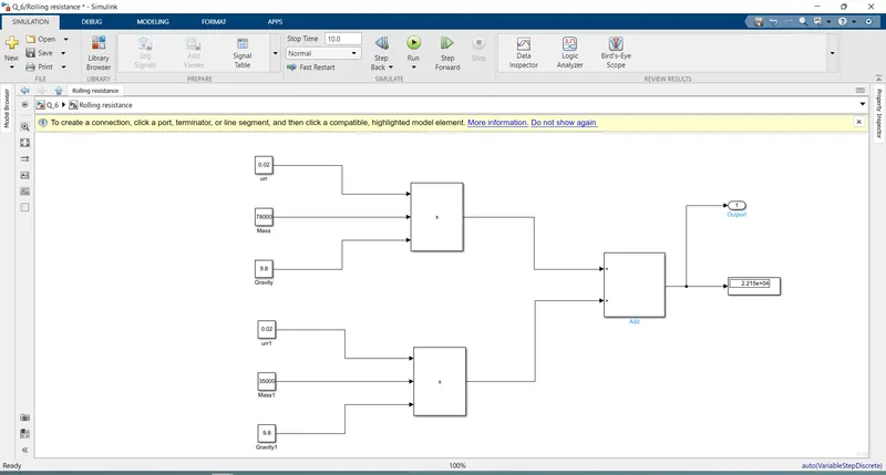
Rolling resistance force (Frr)1 : µrr * m * g
= 0.02 * 78000 * 9.8
= 15288 N
Rolling resistance force (Frr)1 = 15288 N (acting on aircraft)
Rolling resistance force (Frr)2 : µrr * m * g
= 0.02 * 35000 * 9.8
= 6860 N
Rolling resistance force (Frr)2 = 6860 N (acting on towing vehicle)
Total rolling resistance force (Frr) : (Frr)1 + (Frr)2
= 6860 + 15288
= 22148 N
Total rolling resistance force (Frr) = 22148 N
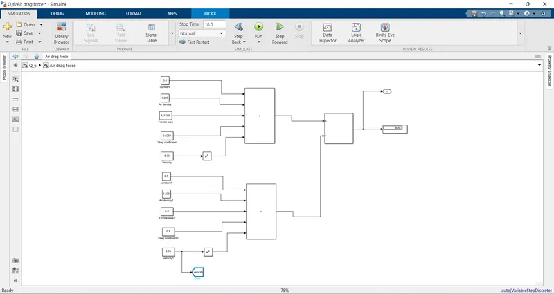
Air drag force (Fad)1 : 1/2 * ρ * A *Cd * V2
= 1/2 * 1.235 * 421.008* 0.0255 * 8.332
= 459.99 N
Air drag force (Fad)1 = 459.99 N (acting on aircraft)
Air drag force (Fad)2 : 1/2 * ρ * A *Cd * V2
= 1/2 * 1.235 * 6.8 * 0.5 * 8.332
= 145.68 N
Air drag force (Fad)2 = 145.68 N (acting on towing vehicle)
Total Air drag force (Fad) : (Fad)1 + (Fad)2
= 459.99 + 145.68
=605.67 N
Total Air drag force (Fad) = 605.67N
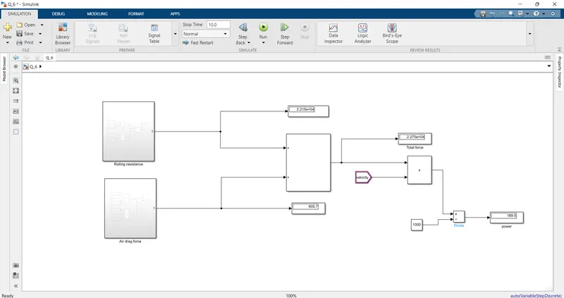
Total force acting (Ft) : Frr + Fad
= 22148 + 605.67
= 22753.67 N
Total power Pt : Ft * V
= 22753.67 * 8.33
= 189538.071 W
= 189.53 Kw
Total power (Pt) = 189.53 Kw
Total force required to push / pull an aircraft by a towing vehicle = 22753.67 N
Total power required to push / pull an aircraft by a towing vehicle = 189.53Kw
Q_6_B Develop the model for the calculated force and power using Simulink.
so here according to the above performed calculations the model is to be build in the SIMULINK .
First I am taking the subsystem as rolling resistance in that i creating a model by using constants,product,add & display as per above calculations and assain the values to the blocks.
And then creating a model for calculation of air drag force by using constants,sum,product & display and connected as per above calculations.
so, if we observe the below image we can see the output values in the display blocks for the both total force and the total power and there will be a slight variation in between the calculated values and the simulated values which is a very minor difference and it is negligable
Q_7
here they asked me to design an electric powertrain with type of motor, it’s power rating, and energy requirement to fulfill aircraft towing application in Simulink
the many values are considered from the above calculations, now we are calculating the energy required for the vehicle
Energy required :
Energy : power * time
From the above calculation the power calculated is
Power (P) : 189.53 Kw
Time is assumed as 20 min which is converted into hours as 0.33 hrs
Time (T) : 0.33 hrs
So, Energy : power * time
= 189.53 * 0.33
= 62.54 Kwh
So, the energy required for above calculated 20 min is 62.54 Kwh
Now lets calculate the input power of the towing vehicle. And the output power is considered from the above calculations and Considering the values of towing vehicle TBL280
Duty cycle : output power / input power
Input power is to be calculated based on the assumptions of motor specifications
Input voltage : 600 V
Input current : 350 A
Now input power : input voltage * input current
= 600 * 350
= 210000 w
= 210 Kw
Total input power = 210 Kw
From the above calculation the duty cycle will be,
Duty cycle : output power / input power
= 189.53 / 210
= 0.90 = 90.25%
Duty cycle = 90.25%
Duty cycle required for towing vehicle TBL280 is 90.25%
Now lets tabulate the whole assumed parameters of the system
|
Parameter |
Values |
|
Aircraft |
|
|
Mass |
78000 kg |
|
Height |
11.76 m |
|
Width |
35.80 m |
|
Air density |
1.235 kg/m3 |
|
Drag coefficient |
0.0255 |
|
Towing vehicle |
|
|
Mass |
35000 kg |
|
Height |
2 m |
|
Width |
3.4 m |
|
Tyre size |
0.5588 m |
|
Drag coefficient |
0.5 |
|
Air density |
1.235 kg/m3 |
|
Speed |
8.33 m/s |
|
Coefficient of rolling resistance |
0.02 |
Here i am taking the dc7_example model in that i am changing the ac source to battery.
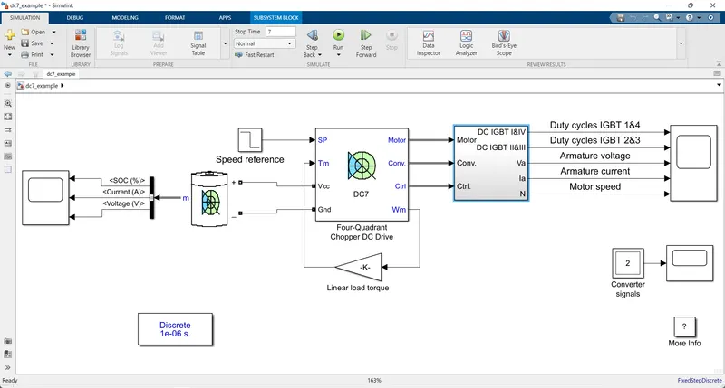
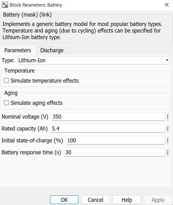
Then battery measurement port is connected to scope after connecting the battery i am changing the parameters.
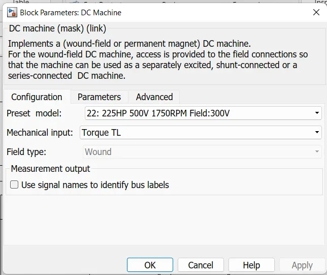
I am selcting the dc motor as 225hp,500V & 1750RPM
then run the simulation the results are shown below
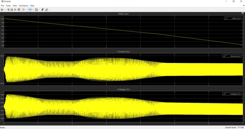
In this battery output graph, we can get the values of state of charge (SOC), current in Amps, Voltage in Volts as above.
From the SOC we can observe that the value is decreased slightly from 100% to 93%. this we can say that the energy utilized by the chopper from the battery.
From the second one is shown current in the battery varies from -450A to 450A
From the second one is shown voltage in the battery 600V.
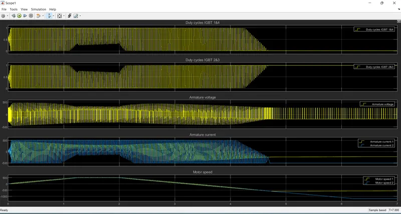
In the above first graph shows IGBT 1 & 4 conduction
Then second graph shows IGBT 2 & 3 conduction
Third graph shows armature voltage of the motor.
Fourth graph shows armature current of the motor
Fifth graph shows the motor speed.
Q_7_B
Design the parameters in excel sheet