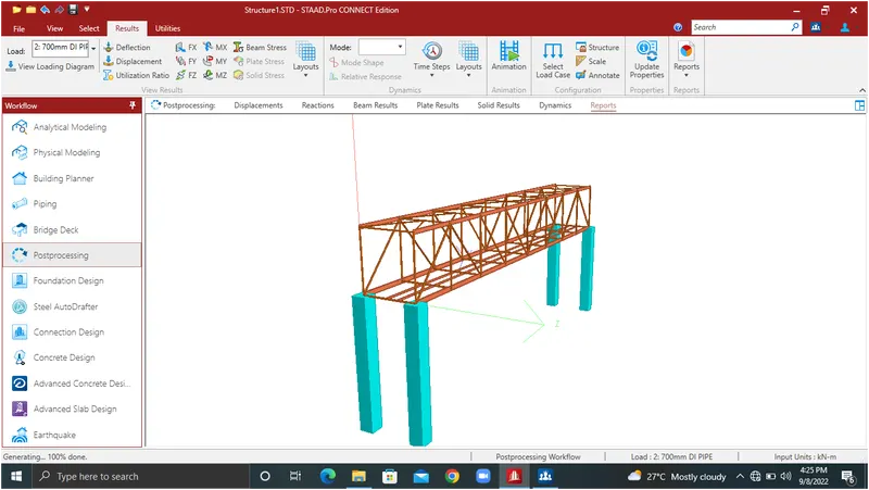
Week 6 Challenge
AIM:
To Create Steel bridge model and Applying pipe load on it and performing analysis using STAAD.pro
GIVEN:
⦁ Width of bridge is 3 M
⦁ Length of bridge is 24 M
⦁ NB DI pipe 700 mm Dia
⦁ NB DI pipe 200 mm Dia
PROCEDURE:
1.To create beam 24M x axis
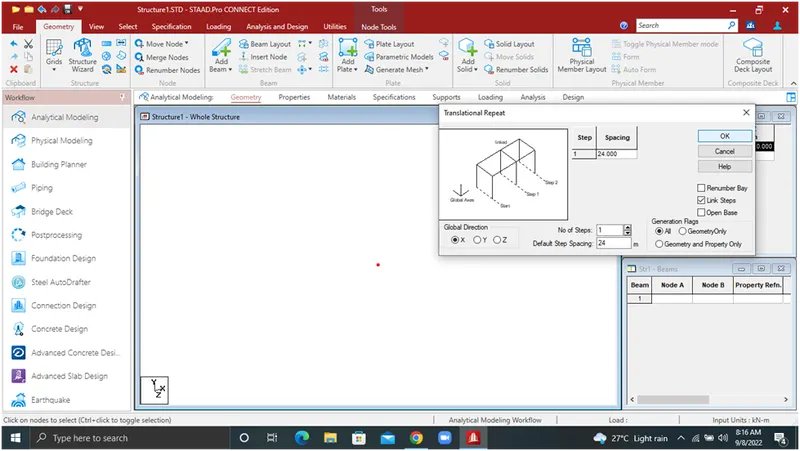
2.Same size 3M distance in z axis direction
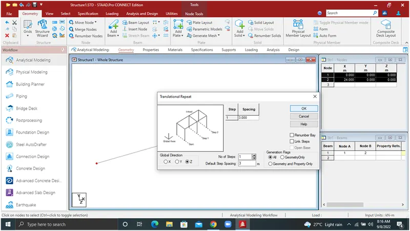
3.To select the z direction 3M beam translation repute 7 steps, 3M spacing
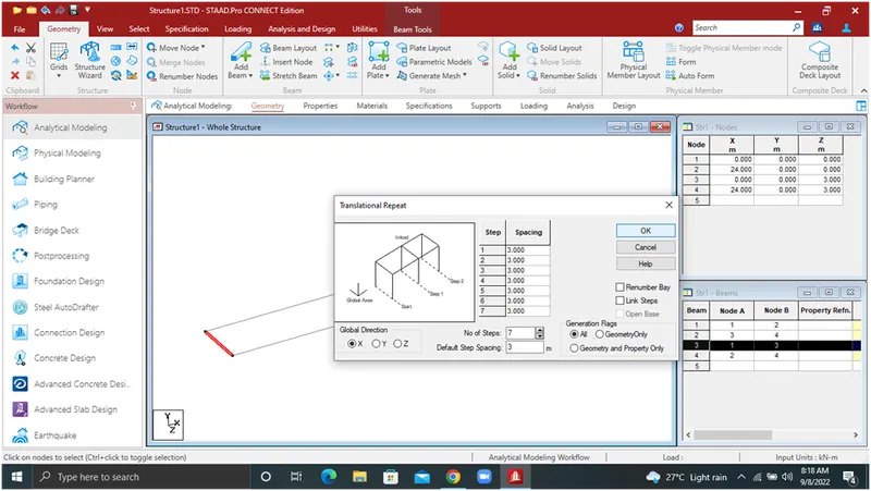
4.Select the all the beams to 3.250m spacing y direction
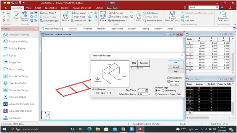
5.In top layer selected nodes to repute in -1.5M z direction
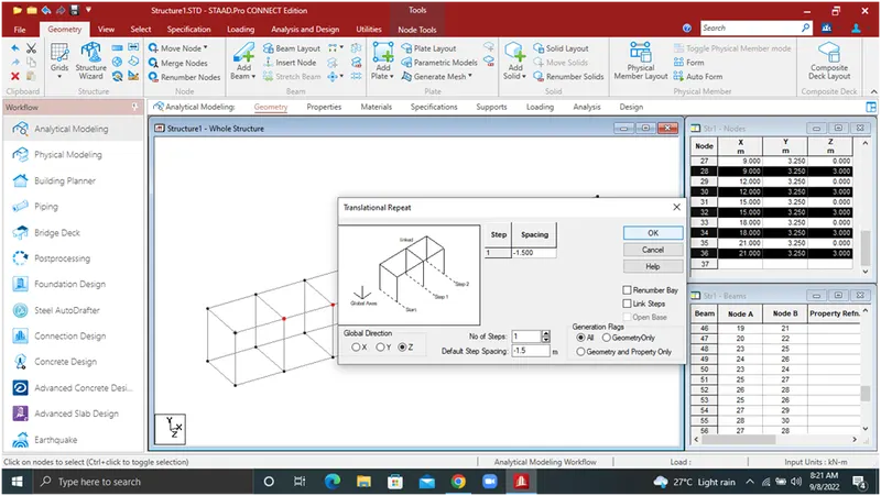
6.To add the beams show in fig
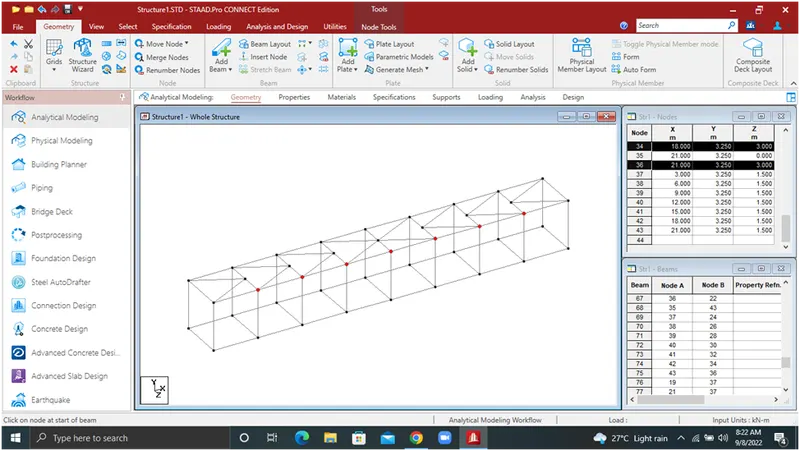
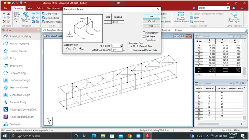
7.To select the corner nodes and spacing -1M from z direction
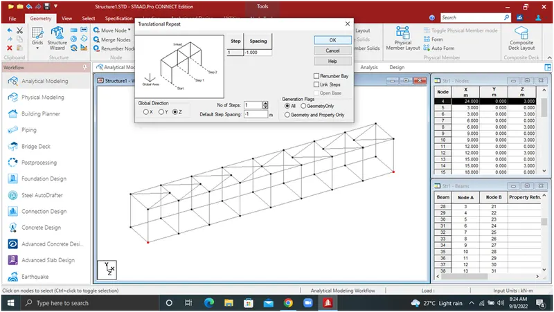
- Selected the two nodes spacing -0.640M z direction
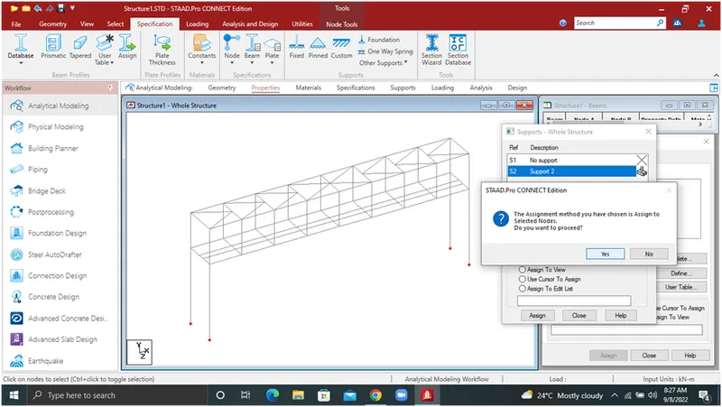
- It is the fixed support so create the pier in four corner y direction -7M
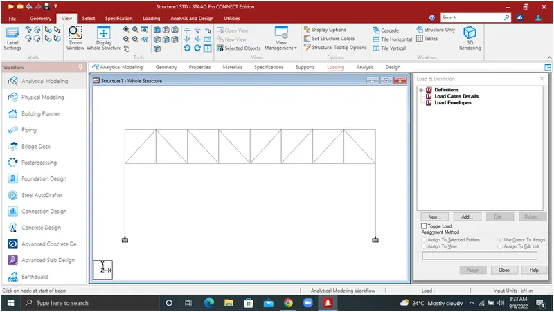
10.To add beams in side
11.The bottom corner beams are ISMC250 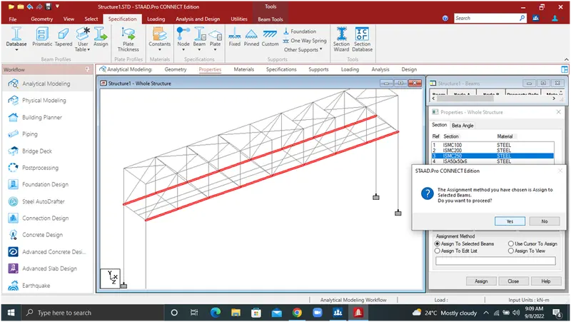
- The top corner beams are ISMC200
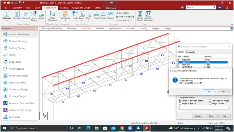
13.The NB DI pipes are ISMB100
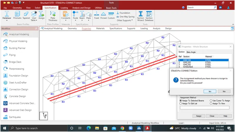
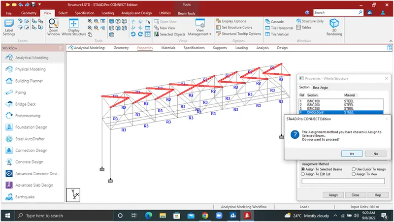
14.Top angles are ISA 50X50X6
15.Selected angles are 90X90X8
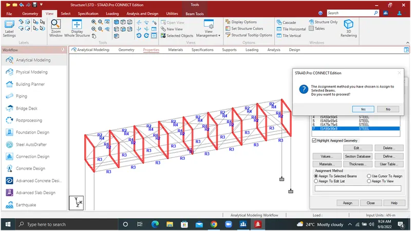
- Remening angles are ISA75X75X6
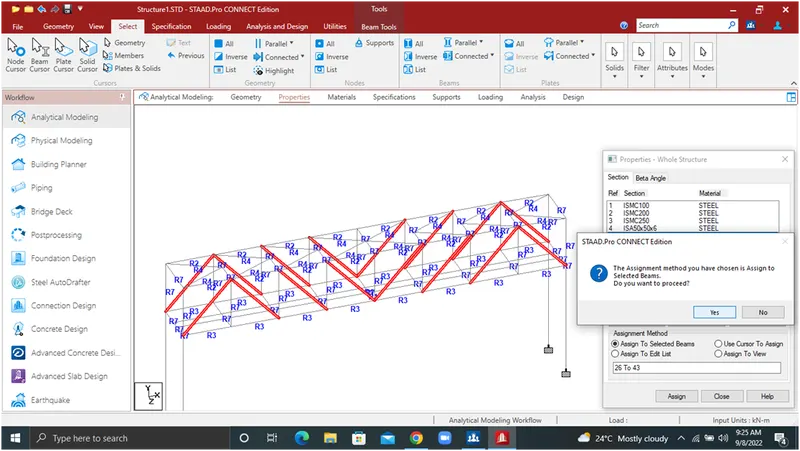
17.The pier size is 0.5mX0.5m
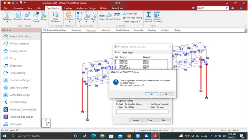
CALCULATION:
The self weight of 700mm DI pipe = 2.1719 Kn/m
Live load = (3.14 x (0.7)²/4 ) x 10
= 3.8465
Total load = self weight + live load
= 2.1719+3.8465
= 5.0184
The self weight of 200mm DI pipe = 0.4528 Kn/m
Live load = (3.14 x (0.2)²/4 ) x 10
= 0.314
Total load = self weight + live load
= 0.452+0.314
= 0.764
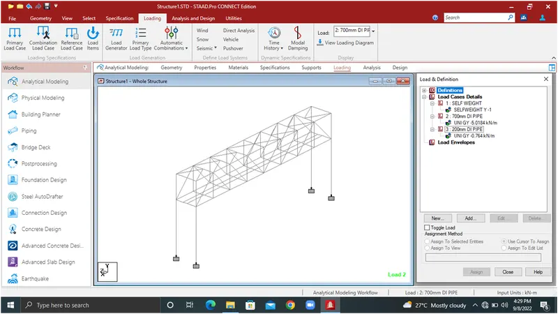
18.Go to loading section and then create self weight -1 y, 700mm DI Pipe -5.0184, 200mm DI Pipe -0.764
19.Run analysis (0 Error, 0 Warnings, 0 Nodes )
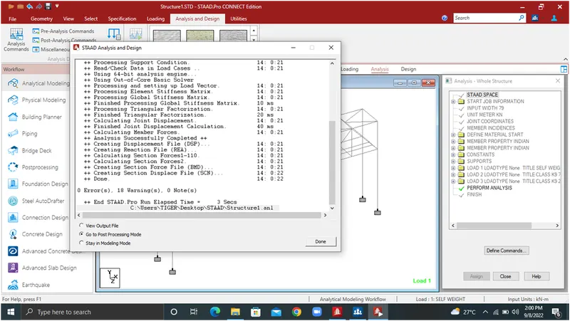
RESULTS
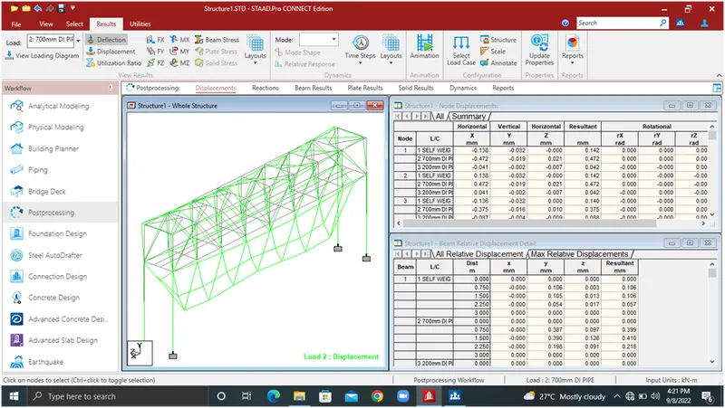
20.deflection
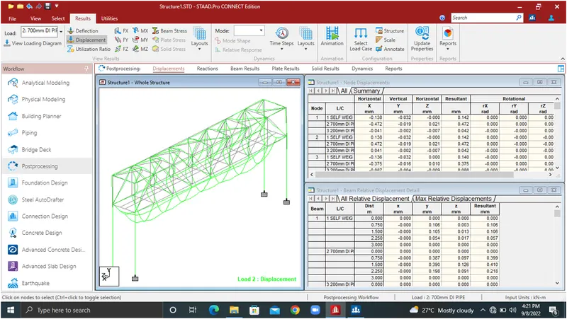
21.Displacement
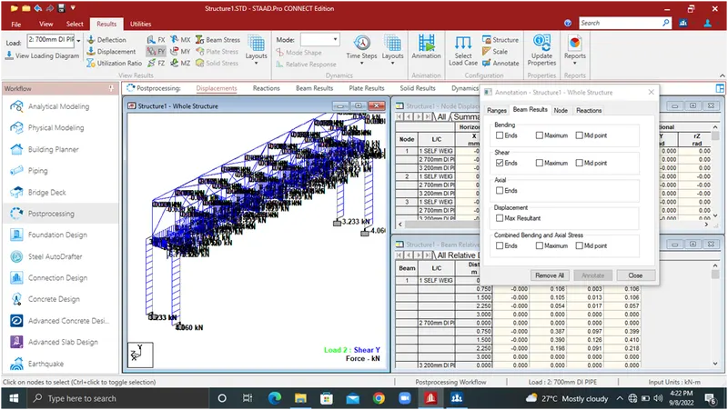
22.Sheyar FY
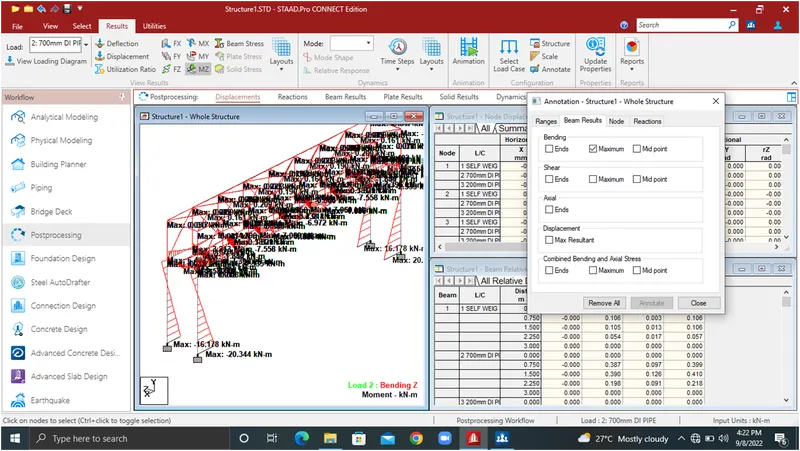
23.Bending moment MZ
- Beam stresses MY
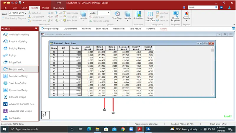
25.Beam stresses MZ
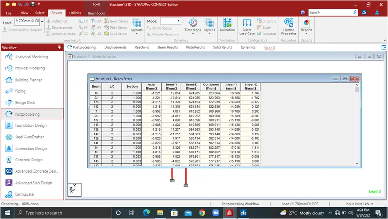
26.3D