Week 3 Challenge
AIM:
1.To define how hydrology and geotechnical studies (preliminary and detail studies, zone of influence) are used in fixing span as per IRC standards and type of bridge and mention the clauses applicable for the same.
2. To determine the scour depth at the pier and abutment location
3. To mention measures to be taken to avoid scour at bridge for shallow foundation and draw the section of measures on the downstream and the upstream
4. To explain what is uplift and how it can affect the foundation. (loss of contact)
5. To calculate the uplift in U trough of given section with height 3,4,5 meters. with water level on top of ramp wall level .
6. To mention different measures that can be taken to avoid uplift.
GIVEN:
The given data has Silt factor =3, Design discharge = 1000 cumecs and Linear waterway = 128m. A U trough is given with carriage way width of 8.2m and footpath 1.2m
Procedure:
1.How hydrology and geotechnical studies (preliminary and detail studies, zone of influence) are used in fixing span as per IRC standards and type of bridge and mention the clauses applicable for the same.
Hydrology Studies:-
Hydrology is the study of the amount and quality of water being stored or conveyed on the land surface, and in soils and rocks near the surface. The hydrological response of a catchment is controlled by a combination of climate, vegetation, drainage, soils and land use.Hydrology in the study of bridge design mainly deals with the properties, distribution, and circulation of water on and above the land surface. The primary objective is to determine either the peak discharge or the flood hydrograph, at the highway stream crossings. The hydrological analysis is required for designing all the bridges over waterways, bridge roadway construction and construction over water profile. typically those should include the following.The horizontal alignment of a highway at a stream crossing should be considered in selecting the design and location of the waterway opening, as well as the crossing profile, Design should be made to align the highway so that the crossing will be normal to the stream flow direction.
Geotechnical Studies:-
Geotechnical engineering is the study of the behavior of soils under the influence of loading forces and soil-water interactions. This knowledge is applied to the design of foundations, retaining walls, earth dams, clay liners, and geo synthetics for waste containment. A geotechnical investigation is the gathering of information about the properties of the soil and rocks beneath the ground that are used when designing foundations or any other structures that require earth properties for the design of any structure onsite. A geotechnical investigation will include surface exploration and subsurface exploration of a site. Sometimes, geophysical methods are used to obtain data sites. Subsurface exploration usually involves soil sampling and laboratory tests of the soil samples retrieved, surface exploration can include geologic mapping, geophysical methods, and photogrammetric.
- Foundation soil and rock condition is primary information required for the economic design and construction of any structure.
- Geotechnical aims:-
- To find out the nature of the soil and rock deposit.
- Depth and thickness of various soil and rock strata for structure foundation requirement.
- Location of Ground Water Table.
- Selection of foundation type and depth.
- Geotechnical engineering assessment of Foundation regarding its load-bearing capacity and settlement aspects.
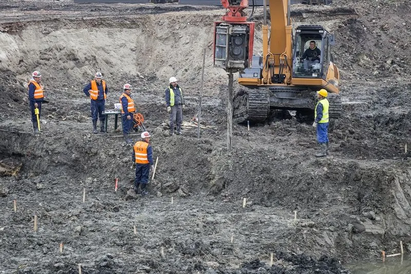
Factor for consideration of Bridge Length:-
- The roadway alignment is at a skew to the streambed, and normalizing the alignment would require unsafe or undesirable curves on the approaches to the bridge.
- Embankment may be limited to a certain location due to local soil instability or permitting requirements.
- Bridge costs might be cheaper than embankment costs.
- Matching the highway profile grade line.
- High potential for a meander to migrate, or other channel instabilities.
Stages of geotechnical investigation:-
- Soil and groundwater conditions
- Topography, drainage pattern, vegetation
- Condition of existing structure
- Suitability of site for the proposed project
- Types of soil and rock formations from geology
- Presence of natural resources
- Stream pattern
- Seismic activity in the area
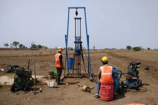
IRC:78-2014-Standard specifications and code of particle for road bridges
Geotechnical report:
- Geological history and geographical background of the area
- Total scope of work and a plot plan showing locations of all tests
- Detailed bore -log /drill-log in the approved format
- Laboratory test results in approved tabular and graphical form with the summary
- True cross-selections/profile of all boreholes and or trail pits
- All geotechnical engineering parameters
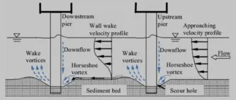
Scouring:-
- The erosion of soil surrounding a bridge foundation, piers and abutment. Scouring occurs when water flows water flows around a bridge with high velocity removes sediments around the bridge foundation, leaving behind scour holes, this will lead to failure of the structure.
- scour is the removal of sediment such as sand and gravel from around bridge abutments or piers , caused by fast flowing water, can carve out scour holes, compromising the integrity of a structure.
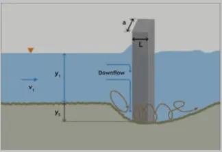
Scour depth:-
Scour depth means the maximum depth of streambed scour caused by erosive forces of the base flood discharge.
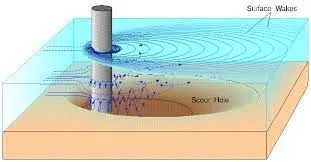
Areas affected by scour:-
Water normally flows faster around piers and abutments making them susceptible to local scour. At bridge openings, contraction scour can occur when water accelerates as it flows through an opening that is narrower than the channel upstream from the bridge. Degradation scour occurs both upstream and downstream from a bridge over large areas. Over long periods of time, this can result in lowering of the stream bed.
Causes:-
Stream channel instability resulting in river erosion and changing angles-of-attack can contribute to bridge scour. Debris can also have a substantial impact on bridge scour in several ways. A build-up of material can reduce the size of the waterway under a bridge causing contraction scour in the channel. A build-up of debris on the abutment can increase the obstruction area and increase local scour. Debris can deflect the water flow, changing the angle of attack, increasing local scour. Debris might also shift the entire channel around the bridge causing increased water flow and scour in another location.
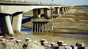
Scouring and Prevention:-
Scouring is defined as the erosion or loss of top bed soil around the bridge piers, abutments, spurs etc due to the water flow currents. Scouring can lead to foundation failure.
Scour creates holes around piers and reduces the stability of the bridge.
The flow speed got changed due to the presence of piers or abutments in the flowing direction which reduces the flow area and it makes changes in flow patterns.
Reduction strengthens the river bed to a certain degree and also slows the water current velocity thus reducing the scouring around the pier.
Construction of barriers upstream of the bridge piers that consist of the number of piles will reduce scouring depth.
Scour depth
Give:-
Slit factor= 3 ,
Design Discharge= 1000 ,
Calculate the mean scour depth= 1.34{(Db^2)1/1/ Ksf}^(1/3)
Dsm= 1.34{(10*10)/3}^1/3
= 1.34*3.21
= 4.31m
For pier scour depth is 2*dsm, So 4.31*2=8.62m
What ids uplift?
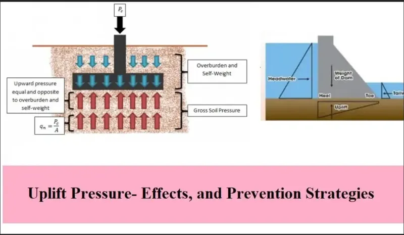
An uplift pressure is any pressure exerted beneath a structure thathas the potential to raise the structure higher level compared to its surroundings.
Uplift, which is also known as hydrostatic uplift, is an upward pressure applied to a structure that has the potential to raise it relative to its surroundings. It is the condition of greater pore water pressure than the overburden pressure of the structure.
An uplift force is any upward pressure applied to a structure that has the potential to raise it relative to its surroundings.
How to Check for Uplift Pressure?
The weight of the substructure should be greater than uplift pressure in order to meet the requirements of applicable codes, i.e. summation of downward load per given area should be larger than that of the vertical load per given area.
The downward load should at least greater than 25% compared to the upward load due to hydrostatic load. The following expression can be used to check the occurrence of uplift force below the structure under considerations:
{ΦW/ẉ(h+1)}=>1.25
where:
Ø: mass reduction factor, can be taken as 0.90
W: the mass of the structure
w: specific weight of water
h: height of water from the water table to the bottom of the foundation
1: Factor of safety
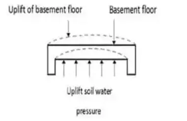
Uplift pressure on Basement
Uplift can affect the foundation:-
- It reduces the effective weight of the structure.
- Endanger stability of the structure
Section 1:-
Considering width will be 1m
Caluclating the total weight of U trough for 3m height based on section wise,
Horizontal Rectangle= (9.2 +0.6+ 0.41)*0.580*25
=148.045kN
Caluclating the total wieght of U trough taking vertical portion of U trough as rectangle throughout.
Vertical Rectangle=2*(3*0.3*1)*25
=45kN
total weight =148.045+45
193.045kN
Section 2:-
Caluclating the total weight of U trough for 4m height based on section wise,
Horizontal Rectangle= (9.2 +0.6+ 0.41)*0.580*25
=148.045kN
Caluclating the total wieght of U trough taking vertical portion of U trough as rectangle throughout.
Vertical Rectangle=2*(4*0.3*1)*25
=60kN
total weight =148.045+60
=208.045kN
Section 3:-
Caluclating the total weight of U trough for 5m height based on section wise,
Horizontal Rectangle= (9.2 +0.6+ 0.41)*0.580*25
=148.045kN
Caluclating the total wieght of U trough taking vertical portion of U trough as rectangle throughout.
Vertical Rectangle=2*(5*0.3*1)*25
=75kN
total weight =148.045+75
=223.045kN
Calculation of uplift along the base the foundation,
For 3m:-
Y*h=10*3.6
=36kN/m2
For 4m:-
Y*h=10*4.6
=46kN/m2
For 5m:-
Y*h=10*5.6
=56kN/m2
Check Uplift Pressure:-
Total weight /Uplift Pressure
For 3m:-
=193.045/36
=5.362362>1
For 4m:-
=208.045/46
=4.5227>1
For 5m:-
=223.045/56
=3.98294>1
Result:-
Hydrology and Geotectnical studies fo fixing span as per IRC standards and type of bridge have been explained.
Check for uplift has been done.