Week 2 Challenge
AIM:
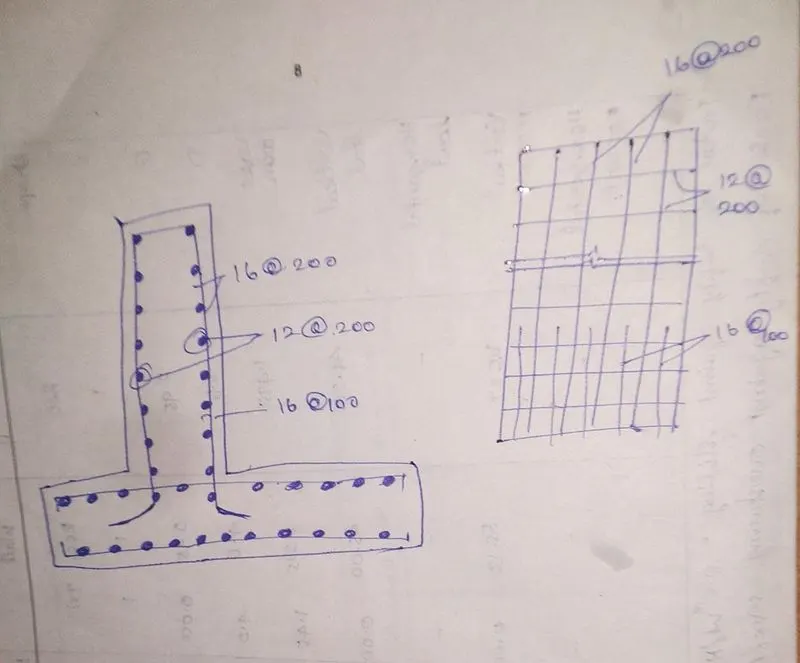
To define all loads to be applied in the abutment of the bridge as per IRC 6 and mention the clauses. And check overturning and sliding and design the section of stem, heel and toe. Also show the detailing of the steel in the foundation and wall
To decide the boreholes location and its depth of exploration in case of shallow foundation. To identify all the parameters we need to get from the site/geotechnical investigation for design of the foundation. List different type of soils/rock (minimum 5) and what criteria should be followed for the shallow foundations for selecting the foundation level, their characteristics and collect a picture of each. Draw a typical borehole showing all the data.
Given:
Height of Abutment is 4 m (from ground level), embedded 2 m ground. SBC = 200 kN/m2 (Eccentricity from bearing and abutment center is 0.3 m ). Use coefficient of friction = 0.5. Soil density = 18 kn/m3.
Procedure:
1.Define all loads to be applied in the abutment of the bridge as per IRC 6 and mention the clauses. (Dead load - IRC 6 2017 CL.203)
The dead load carried by a girder or member shall consist of the portion of the weight of the superstructure (and the fixed loads carried thereon) which is supported wholly or in part by the girder or member including its own weight. The following unit weights of materials shall be used in determining loads, unless the unit weights have been determined by actual weighing of representative samples of the materials in question, in which case the actual weights as thus determined shall be used.
(Live load IRC: 6-2017)
For bridges classified under Clause 201.1, the design live load shall consist of standard wheeled or tracked vehicles or trains of vehicles as illustrated in Figs. 1, 2 & 4 and Annex A or Special Vehicle (SV) as per Clause 204.5, if applicable. The trailers attached to the driving unit are not to be considered as detachable.
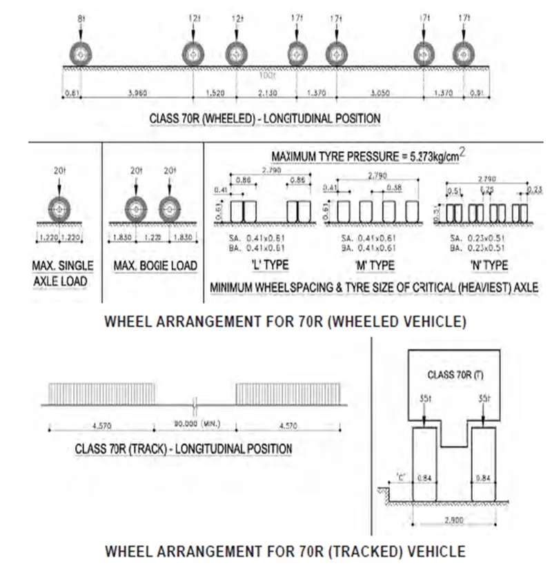
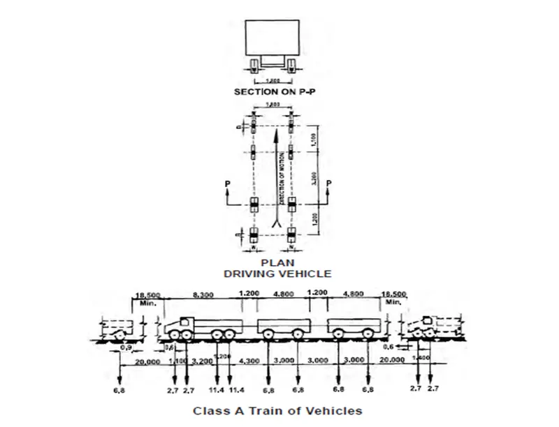
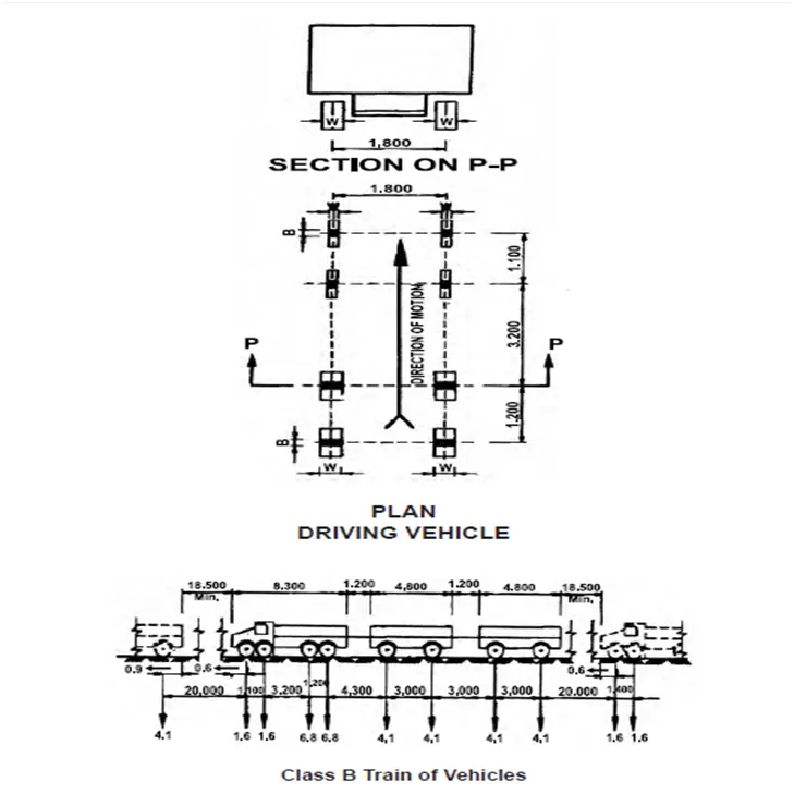
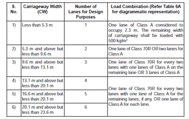
Live load combination:
The carriageway live load combination shall be considered for the design as shown in
Special Vehicle (SV)
IRC Class SV Loading: Special Multi Axle Hydraulic Trailer Vehicle( Prime Mover with 20 Axle Trailer - GVW = 385 Tones ). The longitudinal axle arrangement of SV loading shall be as given
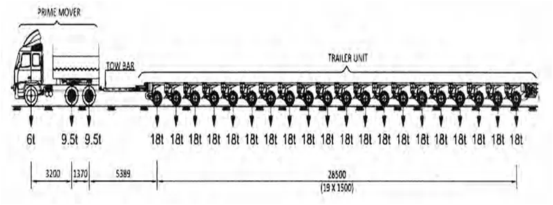
Typical Axle Arrangement for Special Vehicle
The transverse wheel spacing and the axle arrangement of SV loading shall be as given
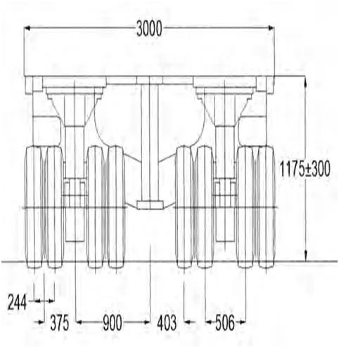
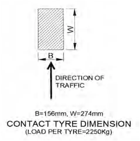
Transverse Wheel Spacing of Special Vehicle
(Reduction of live load is done as per clause 205 of IRC 2017)
205 REDUCTION IN THE LONGITUDINAL EFFECT ON BRIDGES
ACCOMMODATING MORE THAN TWO TRAFFIC LANES
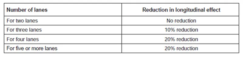
Reduction in the longitudinal effect on bridges having more than two traffic lanes due to the low probability that all lanes will be subjected to the characteristic loads simultaneously shall be in accordance with the Table 8.
Reduction in Longitudinal Effects
Notes:
1) However, it should be ensured that the reduced longitudinal effects are not less severe than the longitudinal effect, resulting from simultaneous loads on two adjacent lanes. Longitudinal effects mentioned above are bending moment, shear force and torsion in longitudinal direction.
2) Table 8 is applicable for individually supported superstructure of multi-laned carriageway. In the case of separate sub-structure and foundations, the number of lanes supported by each of them is to be considered while working out the reduction percentage. In the case of combined sub-structure and foundations, the total number of lanes for both the carriageway is to be considered while working out the reduction percentage.
Footpath Live Load (FPLL) - IRC 6 2017 CL.204
If footpath is present - For all parts of bridge floors accessible only to pedestrians and animals and for all footways the loading shall be 400 kg/m2. For the design of foot over bridges the loading shall be taken as 500 kg/m2
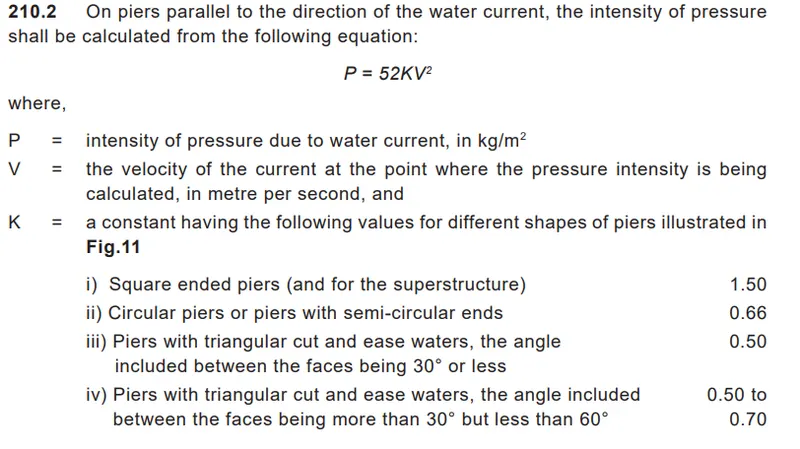
Horizontal forces due to Water current - IRC 6 2017 CL.210
Any part of a road bridge which may be submerged in running water shall be designed to sustain safely the horizontal pressure due to the force of the current.
Earth pressure - IRC 6 2017 CL.214
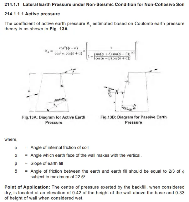
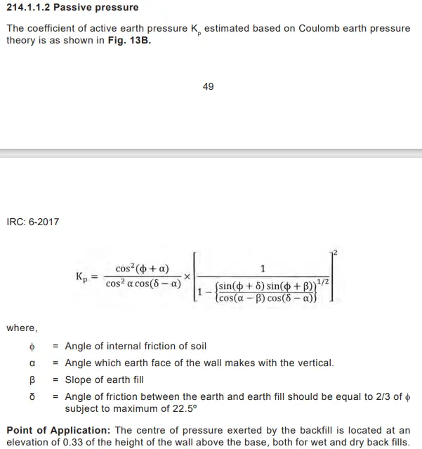
Structure designed to retain earth fills shall be proportioned to withstand pressure calculated in accordance with any rational theory. Coulomb’s theory shall be acceptable for non-cohesive soils. For cohesive soil Coulomb’s theory is applicable with Bell’s correction. For calculating the earth pressure at rest Rankine’s theory shall be used.
Buoyancy in HFL case - IRC 6 2017 CL.213
In the design of abutments, especially those of submersible bridges, the effects of buoyancy shall also be considered assuming that the fill behind the abutments has been removed by scour. To allow for full buoyancy, a reduction shall be made in the gross weight of the member affected by reducing its density by the density of the displaced water.
Note:
1) The density of water may be taken as 1.0 t/m3
2) For artesian condition, HFL or actual water head, whichever is higher, shall be considered for calculating the uplift.
In the design of submerged masonry or concrete structures, the buoyancy effect through pore pressure may be limited to 15 percent of full buoyancy.In case of submersible bridges, the full buoyancy effect on the superstructure shall be taken into consideration.
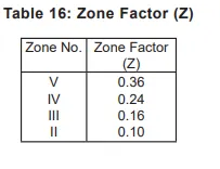
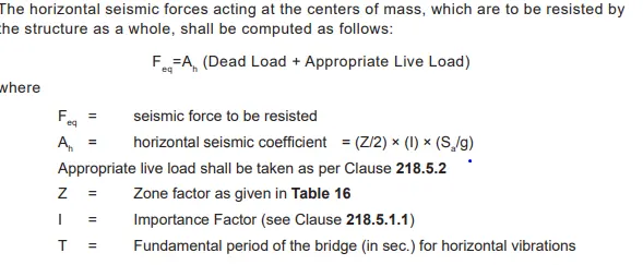
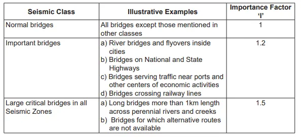
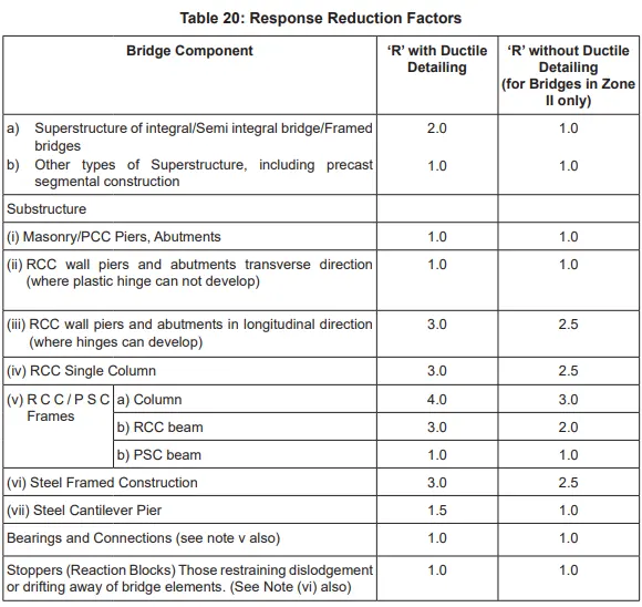
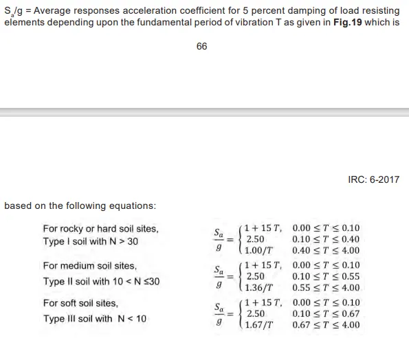
Seismic Load - IRC 6 2017 CL.218
Seismic Zone considered as per Map
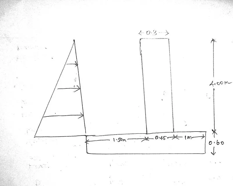
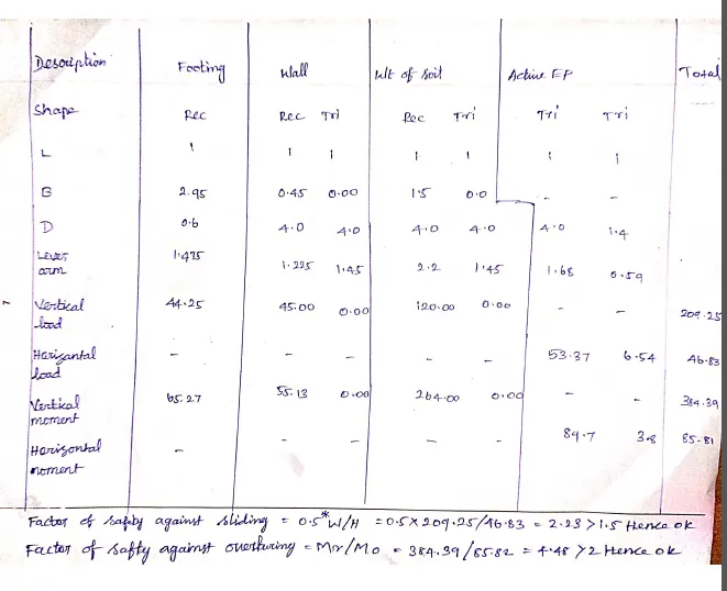
2.Check overturning and sliding of 4 m height of Abutment (from ground level) , embedded 2 m in ground.
Check for overturning and sliding:
Input Data:
Dimensions
Top width of the retaining wall = 300mm
Bottom width of Retaining wall = 450mm
Size of foundation = 1000 x 2950 x 600 mm
Width of toe = 1000mm
Width of heel = 1500mm
Length of Retaining wall = 1m
Concrete & Steel Data
Grade of Concrete = M30
Grade of Steel = Fe500
Unit Weight of Concrete = 25kN/m3
Soil Data
Unit Weight of Soil = 20kN/m3
Angle of internal friction of Soil = 30 deg
Surcharge angle = 0 deg
Angle of inclination of wall from vertical face = 90 deg
Angle of friction between wall & soil = 20 deg
Safe Bearing Capacity of Soil = 200kN/m3
3.A borehole and Geotechnical investigation of the site:
- Borehole investigations are done to get the properties of materials underneath soil layers, The type of foundations is given based on the condition of the soil layers.
- To perform a borehole investigation, we need to decide the number of boreholes to be drilled,
The borehole depends on factors
- Plot coverage of the building.
- The scale of the project.
- Structural loading and load distribution arrangments.
- Condition of the ground.
- Importance of the structure.
A borehole is a deep vertical hole with a small diameter drilled into the ground to obtain soil samples for soil investigation required for the construction of the suitable foundation for the planned structure.
The depth of Exploration carried out to a depth up to which the increase in pressure due to structural loading is likely to cause perceptible settlement or shear failure of the foundation, which depends upon the following factors,
- Type of structure
- Load on structure
- Size and shape of the foundation
- Position of loaded areas
- Soil profile and its properties
The depth of exploration should be one and half times to two times the estimated width of the footing, single or combined, from the base level of the foundation.
Site Investigation:
- Soil Exploration (Boring Holes)
- Collection of Soil Samples
- Conducting the in-situ tests
- Study of Groundwater conditions and Collection of water
sample for chemical analysis
- Preparation of Drawings, Charts, etc
- Analysis of Data Collected
- Preparation of Repor
TYPES OF SOIL :
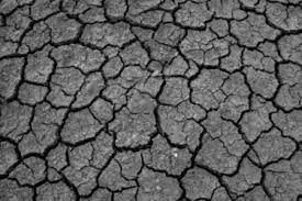
- Black cotton soil: It is a residual soil containing a high percentage of the clay mineral – montmorillonite. It has a very low bearing capacity and high swelling and shrinkage properties.
- Clay: It consists of microscopic and sub-microscopic particles derived from the chemical decomposition of rocks. It contains a large number of clay minerals. It can be made of plastic by adjusting the water content. It exhibits considerable strength when dry. Clay is a fine-grained soil. It is cohesive soil. The particle size is less than 0.002mm.

- Gravel: It is a type of coarse-grained soil. The particle size ranges from 4.75mm to 80mm. It is a cohesion-less material.
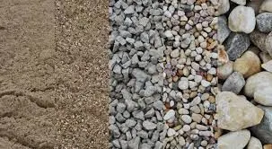
- Sand: It is coarse-grained soil, having a particle size between 0.075 mm to 4.75 mm. The particles are visible to the eye. The soil is cohesionless and pervious.
- Peat: It is a type of organic soil having fibrous aggregates of macroscopic and microscopic particles. It is formed from vegetal matter under conditions of excess moisture, such as in swamps. It is highly compressible and not suitable for foundation

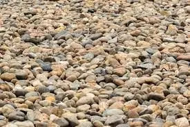
- Cobbles: Cobbles are large size particles in the range of 80mm to 300mm.
criteria Shallow foundation level :
Soil layer: The topsoil is organic soil or waste, which should be completely removed and the foundation is placed below the topsoil. If the topsoil extends to a larger depth, it may be replaced with a suitable backfill material and the foundation may be placed at the minimum depth.
Soil strength: The foundation should be taken to a level where soil with reasonably high bearing capacity and less compressibility is available. This is the usual rule unless the depth to the hard stratum is very large. This will mainly ensure that the size of the foundation is not excessively large and hence economical.
Groundwater: The foundation should be located above the groundwater table (GWT) to avoid undesirable effects of the groundwater on the foundation as well as the foundation soil. However, the GWT level changes with seasons.
Scour Depth: all bridges, the foundations should be located below the maximum scour depth plus the minimum grip length below the highest flood level.
RESULT :
- The recommended borehole depth is equal to one to three times the width of the loaded area.
- Hence the parameters taken for geotechnical investigation have been explained and the condition for sliding, overturning conditions were explained.
- The soil investigation report is the final document of the sub-soil investigation which contains important information’s for the designer. The report must be prepared in such a manner that the reader is able to get a complete picture of the subsurface condition of the site.
A good soil report should include the following:
1. Introduction
2. Borehole log
3. Method of investigation
4. Laboratory test results
5. Analysis of results
6. Recommendations.