Week - 4
1. Control logic of a washing machine
AIM: To implement control logic of a “washing machine” using Stateflow as per given sequence
- If the power supply is available, the system gets activated
- If the Water supply is not available, stop the process & indicate through LED
- Soaking time should be 200s followed by Washing time of 100s.
- Then rinsing happens for next 20s & dryer runs for 50s
Control logic is the part of a controller that defines how a reactive system responds to events or conditional changes. Applications for control logic include:
- Supervising how to switch between different modes of operation
- Scheduling a sequence of tasks or steps for a system
- Defining fault detection, isolation, and recovery logic
Stateflow provides a graphical language that includes state transition diagrams, flow charts, state transition tables, and truth tables. You can use Stateflow to describe how MATLAB algorithms and Simulink models react to input signals, events, and time-based conditions.
Stateflow enables you to design and develop supervisory control, task scheduling, fault management, communication protocols, user interfaces, and hybrid systems. Graphical animation enables you to analyze and debug your logic while it is executing.
OBJECTIVE:
- To create control logic of washing machine using Stateflow
- Provide Power supply and Water supply as input from Simulink editor
- Turn ON the lamp to indicate the completion of all processes
BODY OF CONTENT:
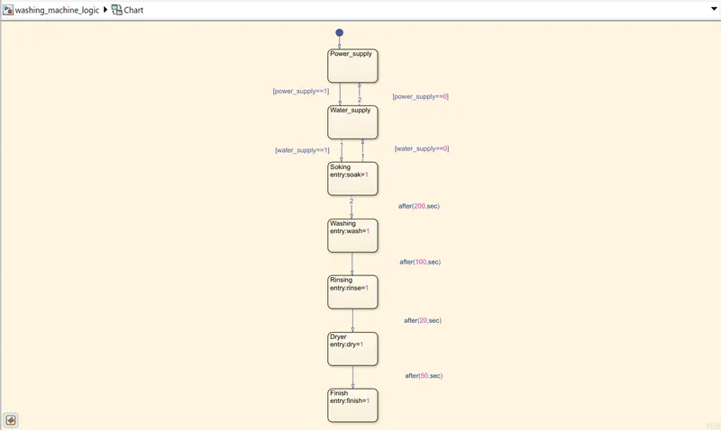
- Below figure shows the flowchart consisting various states and transitions which are used to implement the control logic of washing machine
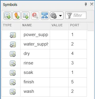
- Below figure shows the Symbols pane window consisting of input and output data, and the port information
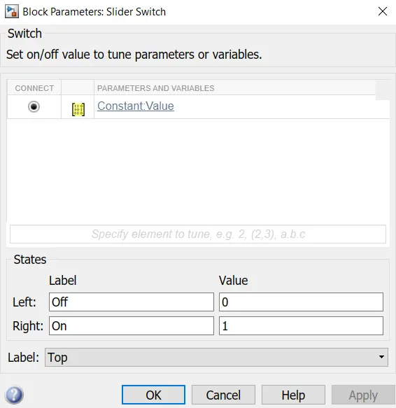
- Below figure shows the Slider Switch block parameters, connected to Constant block, which is power supply input and parameter Value 0 means OFF and 1 means ON
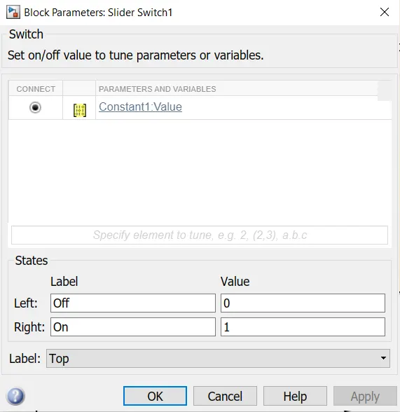
- Below figure shows the Slider Switch block parameters, connected to Constant block, which is water supply input and parameter Value 0 means OFF and 1 means ON
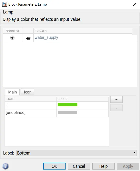
- Below figure shows the Lamp block parameters, which is connected to water supply signal from Constant block, and it glows green if signal value is 1 and it will remain gray if value is 0
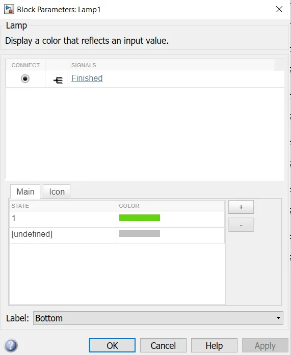
- Below figure shows the Lamp block parameters, which is connected to finished signal from Chart block, and it glows green if signal value is 1 and it will remain gray if value is 0
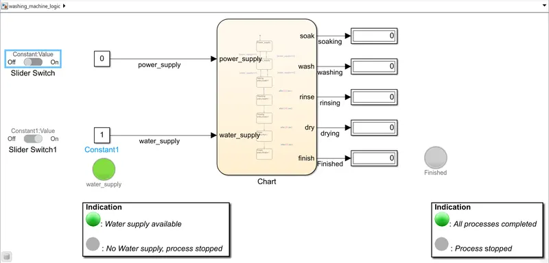
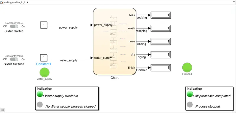
- Below figures shows the Simulink model implementing the control logic of washing machine
Power supply: OFF
Water supply: ON
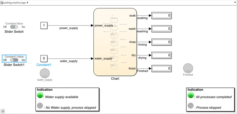
Power supply: ON
Water supply: OFF
Power supply: ON
Water supply: ON
EXPLAINATION:
- Initially we construct a Stateflow chart of washing machine
- Inside Stateflow chart, we use states and transitions to create control logic
- All states are connected by transitions and each transitions have conditions, if condition satisfies then only transition can take place between states
- In this control logic the conditions are,
- If power supply is available, the system activates
- If the Water supply is not available, stop the process & indicate through LED
- Soaking time should be 200s followed by Washing time of 100s.
- Then rinsing happens for next 20s & dryer runs for 50s
- After defining conditions, ‘Symbols pane’ is used to Resolve Undefined Symbols, and number the input and output ports
- Once this is done open Simulink editor and connect Constant blocks as input signals for power supply and water supply
- Connect these Constant blocks with Slider Switches to turn ON and OFF the supplies
- Connect Lamp block to water supply signal block to indicate if water supply is available or not, lamp glows green if water supply available otherwise it remains gray
- Connect Display blocks to the output signals from Chart to observe if process is complete
- Connect Lamp block to finished signal from Chart to indicate if all processes are complete or not, lamp glows green if all processes are complete otherwise it remains gray
CONCLUSION: Control logic of a washing machine is implemented using Stateflow. Slider Switches are used to turn ON and OFF the power and water supply. Lamps are used to indicate if the water supply is available and if the process is finished
2. Simulink chart for the “Gear shift” logic
AIM: To make a Simulink chart for the “Gear shift” logic as per the given conditions
Speed Range(kmph) Gear
0 to 15 1
16 to 25 2
26 to 40 3
41 to 60 4
Above 61 5
Gear shift, Gear stick or Gear lever, more formally known as a transmission lever, is a metal lever attached to the transmission of an automobile. The term gear stick mostly refers to the shift lever of a manual transmission, while in an automatic transmission, a similar lever is known as a gear selector. A gear stick will normally be used to change gear whilst depressing the clutch pedal with the left foot to disengage the engine from the drivetrain and wheels.
OBJECTIVE:
- Make a Simulink chart for Gear shift logic as per the conditions
- Give speed input while the simulation is running and display the gear number
BODY OF CONTENT:
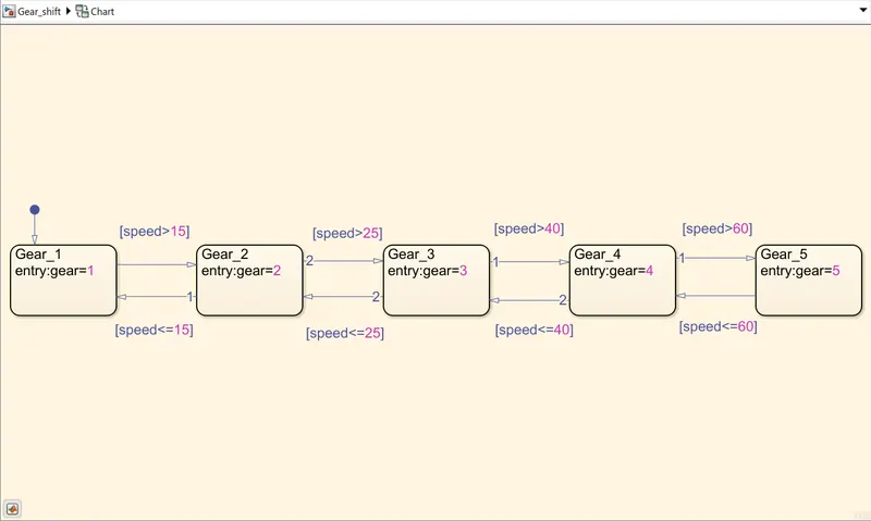
- Below figure shows the flowchart consisting various states and transitions which are used to implement the logic of Gear shift
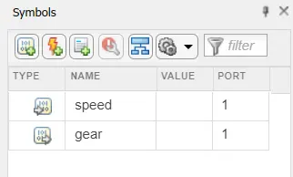
- Below figure shows the Symbols pane window consisting of input and output data, and the port information
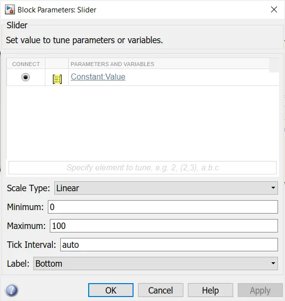
- Below figure shows the Slider block parameters which is connected to a Constant block, and its Minimum and Maximum values are set to 0 and 100 respectively, which will be indicating speed in km/h
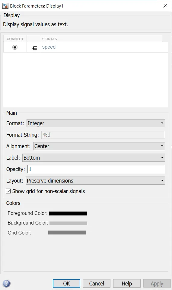
- Below figure shows the Display block parameters which is connected to speed signal of Constant block and displays speed as we change the speed input using Slider block
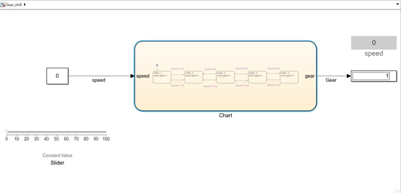
- Below figure shows Simulink model of Gear shift logic using the Stateflow Chart, where speed is 0 kmph and gear number is 1
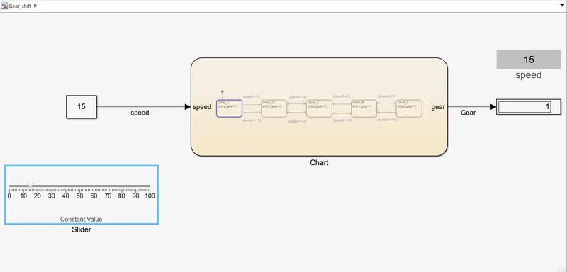
- When speed is 15 kmph, the gear number is 1 as per condition: (0 -15) kmph – gear 1
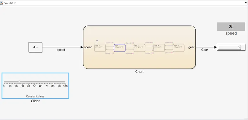
- When speed is 25 kmph, the gear number is 2 as per condition: (16-25) kmph – gear 2
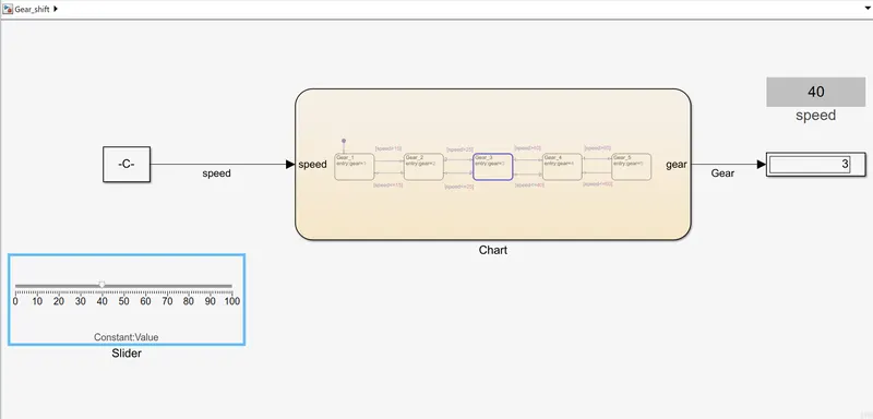
- When speed is 40 kmph, the gear number is 3 as per condition: (26 -40) kmph – gear 3
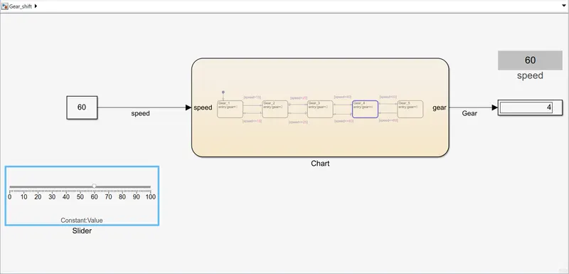
- When speed is 60 kmph, the gear number is 4 as per condition: (41-60) kmph – gear 4
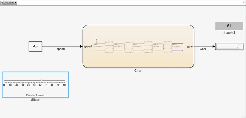
- When speed is 61 kmph, the gear number is 5 as per condition: (above 60) kmph – gear 5
EXPLAINATION:
- Initially we construct a Stateflow chart of Gear shifting logic
- Inside Stateflow chart, we use states and transitions to create logic according to given conditions
- All states are connected by transitions and each transitions have conditions, if condition satisfies then only transition can take place between states
- After defining conditions, ‘Symbols pane’ is used to Resolve Undefined Symbols
- Once this is done open Simulink editor and connect Constant block as an input signal for speed, which will decide the transition between states i.e., gears
- Two display blocks are used to observe Speed and current gear number
- Speed is varied while simulation is running using Slider and the change in gears is observed where Stop time was set to infinite(inf)
CONCLUSION: The Simulink chart for Gear shift logic is made as per given conditions. The Stop time is set to ‘inf’ and run the simulation during which the speed is varied using slider and the change in gear is observed using Display block