Week 8 - Challenge 4 - Coin Holder Design
Coin Holder Design
Tooling Axis: It is the axis along which the core or cavity moves.
Class-A: It is a term used specifically in automotive design. It describes the final production surface data for the aesthetic parts of the car.
Class-B: Class B surfaces are the secondary surfaces that you can see sometimes, but are less important, such as the inside of your glovebox, ash tray, etc.. These must be smooth and "error-free" as well, but are not held to the standards that class A surfaces are.
Class-C: The Class C finish allows more imperfections than Class A or B. Class C is often specified for interior surfaces not readily visible, surfaces that will be covered by another part when assembled, or surfaces which the Customer feels do not need to meet a high cosmetic finish.
PROCEDURE:
- Check if the class A surface is properly joined and has no discontinuity.
- For checking continuity use Join or Boundary command.
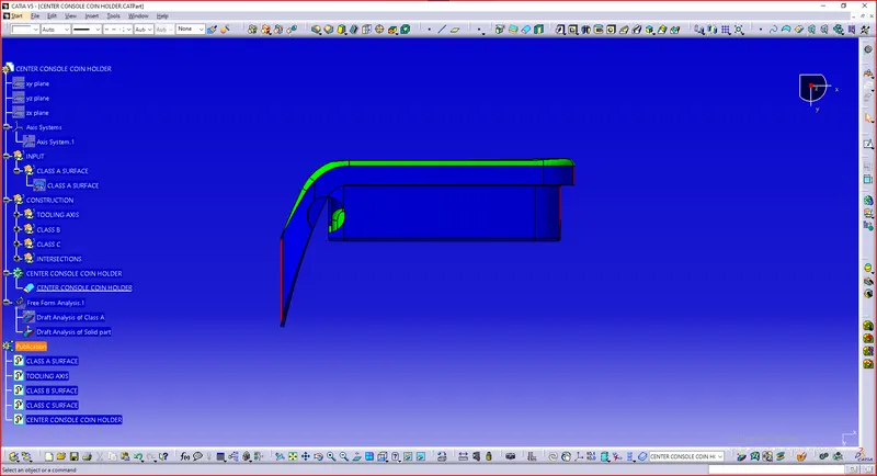
Class A Surface
TOOLING AXIS CREATION:
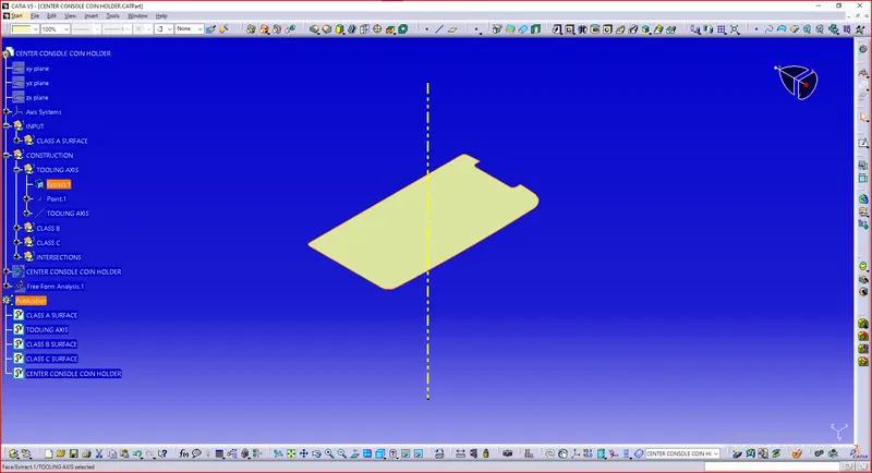
- Check for the suitable tooling direction. Usually, a perpendicular axis to large flat surface or hole is considered as a tooling axis.
- Extract base and create a line with point, perpendicular to the base surface.
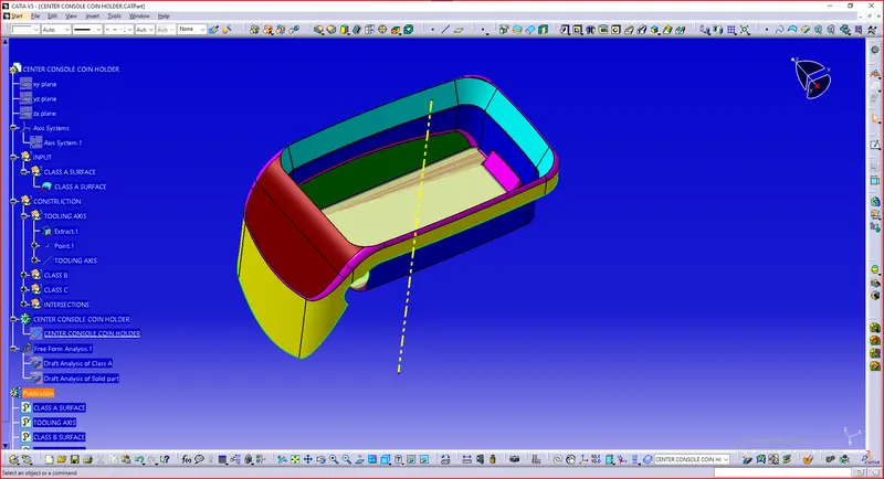
Tooling Axis
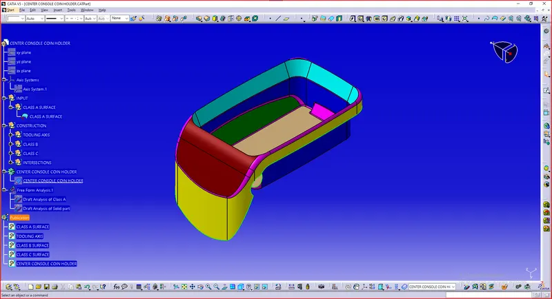
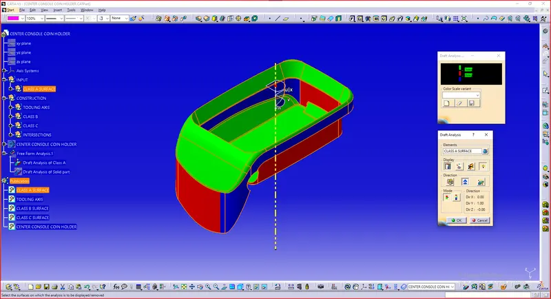
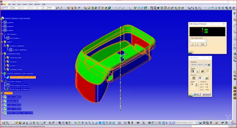
Draft Analysis of Class A Surface
- The green surfaces are having draft angle of more than 3 degrees and they can clear the tooling direction.
- The red surfaces are having draft angle more than 0 degrees and less than 3 degrees.
- The blue surfaces are having negative draft angle.
- So this Class A surface cannot be manufactured as surfaces cannot clear in tooling direction. This Class A surface has to be modified and the walls should have some positive draft angle.
CLASS B SURFACE
- Wall top edges in class A surface have a fillet of radius 5.5mm. In class B surafce the fillet radius would be 5.5-2.5 = 3mm i.e., (fillet radius - thickness). With 3mm radius, the fillets were not proper as shown in below figure. So 2mm fillet radius is used. And for the Base the fillet radius in Class A is lesser than the thickness, so a fillet radius of 1mm is used.
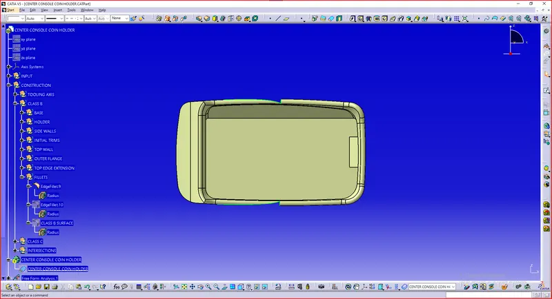
Class B Surafce
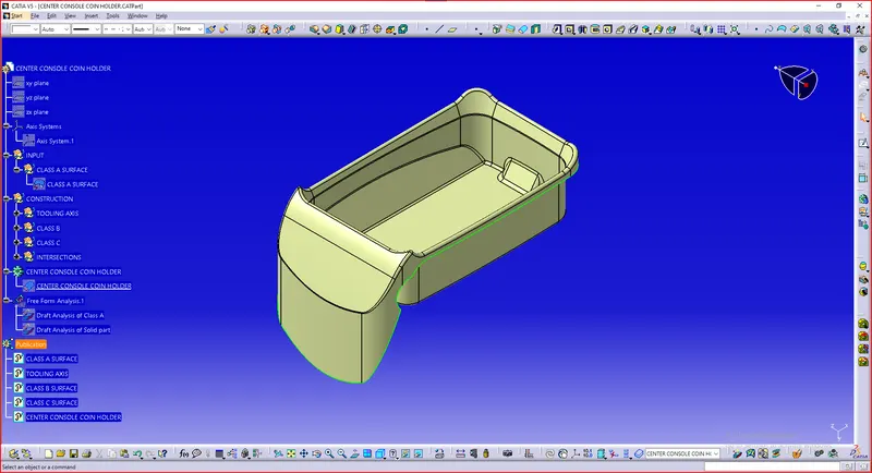
CLASS C SURAFCES
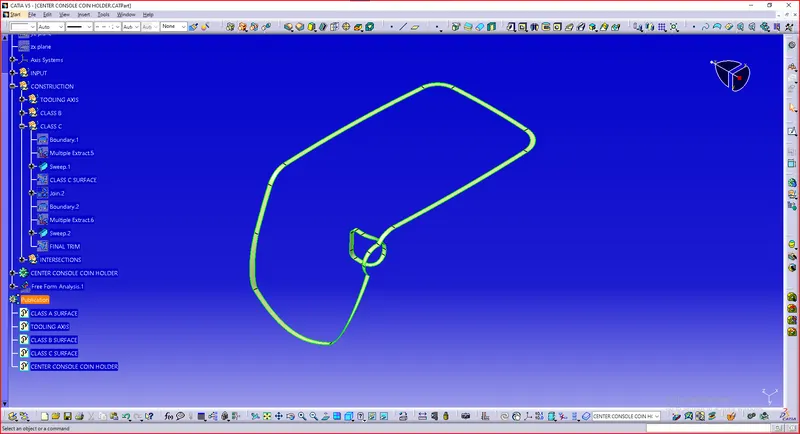
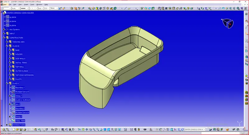
Joining Class B and Class C surface.
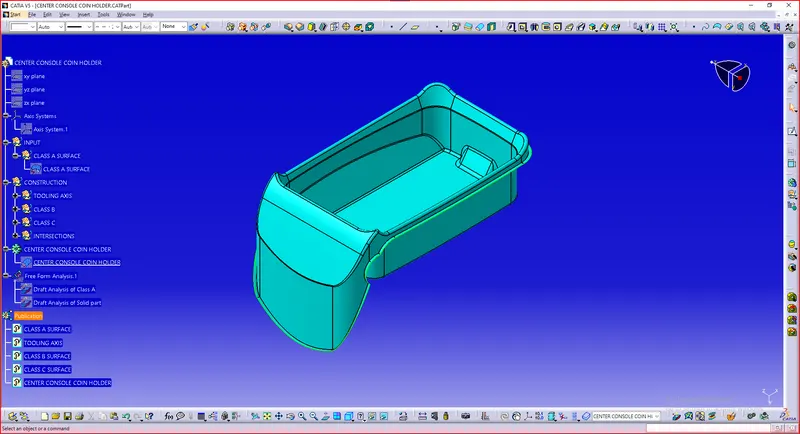
Trimming Class A surface with Class B and Class C.
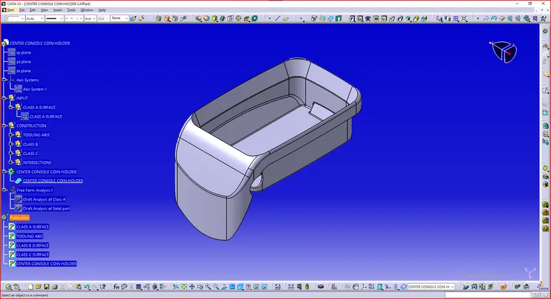
Solid part after using CLOSE SURFACE tool.
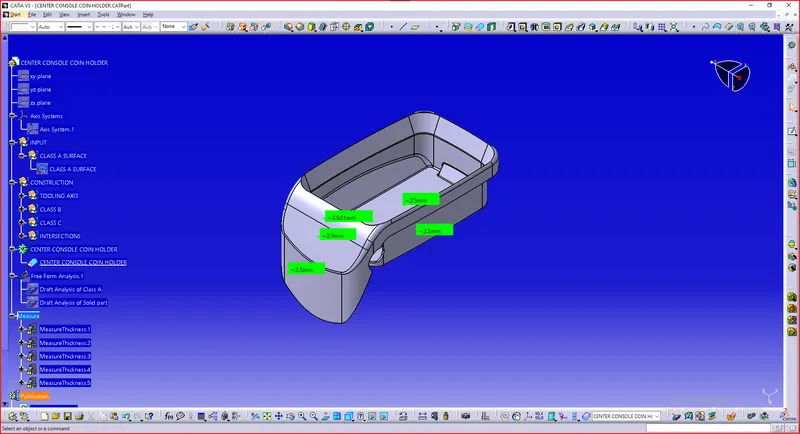
Solid part with thickness of 2.5mm
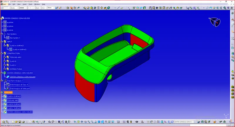
Draft Analysis of Solid Part
- The green surfaces are having draft angle of more than 3 degrees and they can clear the tooling direction.
- The red surfaces are having draft angle more than 0 degrees and less than 3 degrees.
- The blue surfaces are having negative draft angle. As the Class A surface is not manufacturable, the same problem can be seen in the solid part. The Class A surface has to be modified and the walls should have some positive draft angle.
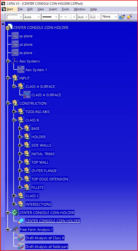
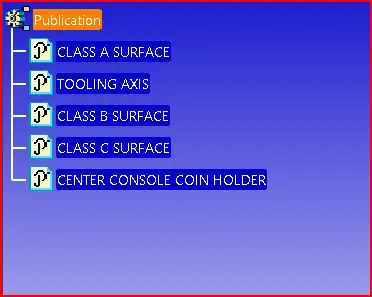
Tree Structure
ORIENTATION:
Isometric view
Front view
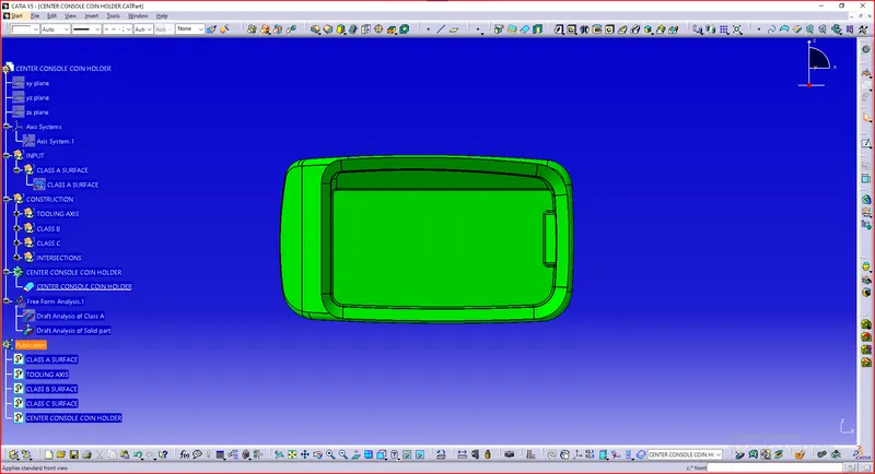
Right side view
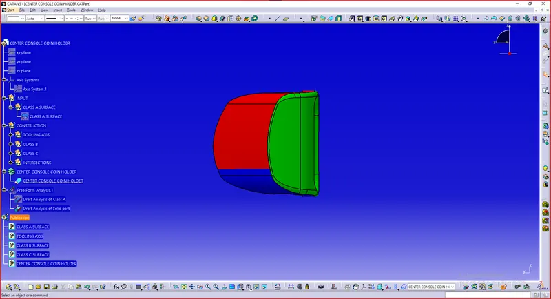
Left side view
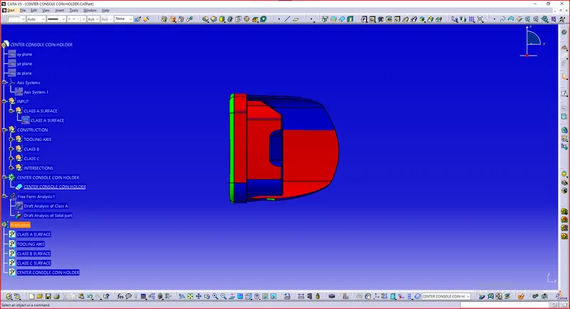
Top view
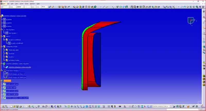
Bottom view