Week 8 - Challenge 5 - Core & Cavity Design
CORE AND CAVITY DESIGN FOR SWITCH BEZEL
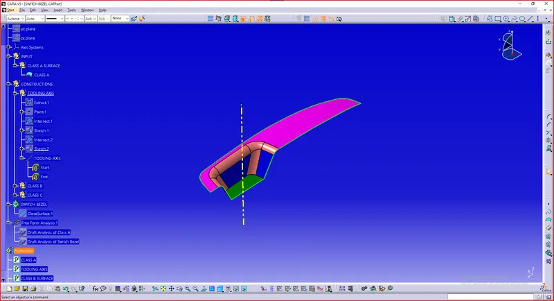
Tooling Axis: Axis along which the core and cavity moves.
Class-A: It is a term used specifically in automotive design. It describes the final production surface data for the aesthetic parts of the car.
Class-B: Class B surfaces are the secondary surfaces that you can see sometimes, but are less important, such as the inside of your glovebox, ash tray, etc.. These must be smooth and "error-free" as well, but are not held to the standards that class A surfaces are.
Class-C: The Class C finish allows more imperfections than Class A or B. Class C is often specified for interior surfaces not readily visible, surfaces that will be covered by another part when assembled, or surfaces which the Customer feels do not need to meet a high cosmetic finish.
PROCEDURE:
- Check if the class A surface is properly joined and has no discontinuity.
- For checking continuity use Join or Boundary command.
Tooling Axis creation:
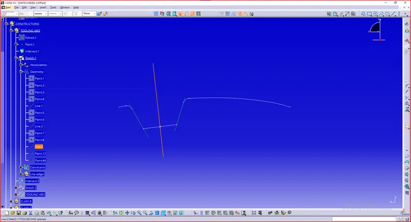
- Create a sketch on the ZY plane and the Switch Bezel to create a reference tooling axis.
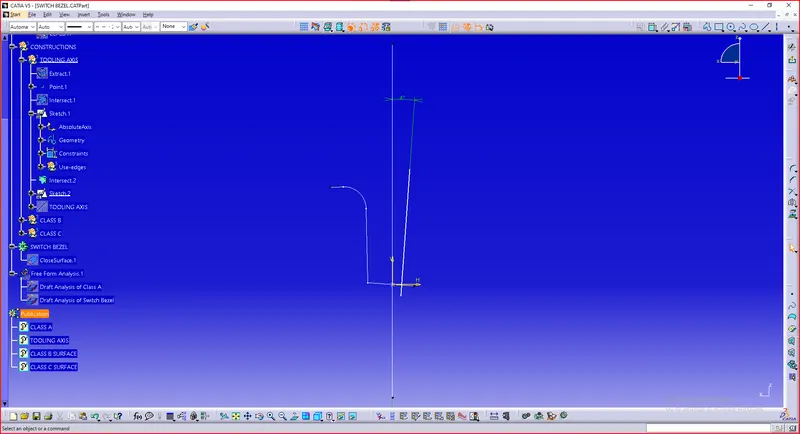
- Create a sketch on the ZX plane and the Switch Bezel to create a reference tooling axis.
- From the above two reference axis, Bisecting the lines to create the TOOLING AXIS.
Draft Analysis of Class A Surface:
- Insert->Analysis->Feature Draft Analysis
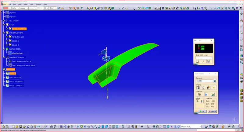
- Drag the Compass and align it with the Tooling axis.
- Click on the Class A surface and it will be differentiated with colours according to the Draft angle of the surface with the tooling axis. If the colour is Green, the draft angle is more than 3 degrees and it will clear the tooling axis, if colour is Red, the draft angle is more than 0 degrees and less than 3 degrees, if colour is Blue, draft angle is less than 0 degrees and it won’t clear tooling axis and draft angle must be changed.
Draft Analysis of Class A
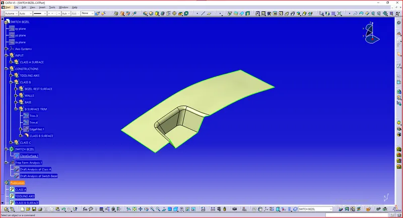
Class B Surface creation:
- Extract Bezel Rest Surface, Walls and Base. Untrim them and extrapolate.
- Trim these surfaces together and Offset by 2.5mm.
Final Class B surface.
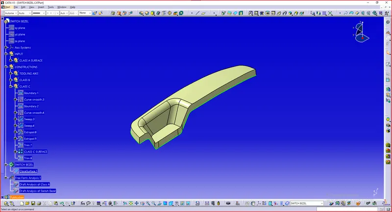
Class C Surface creation:
- Extract outside Boundary of the Class A surface.
- Sweep the Extracted Boundary using Tooling direction as the draft direction. Give 3mm Draft angle.
- Join Class A and Class C surface.
Final Class C surface.
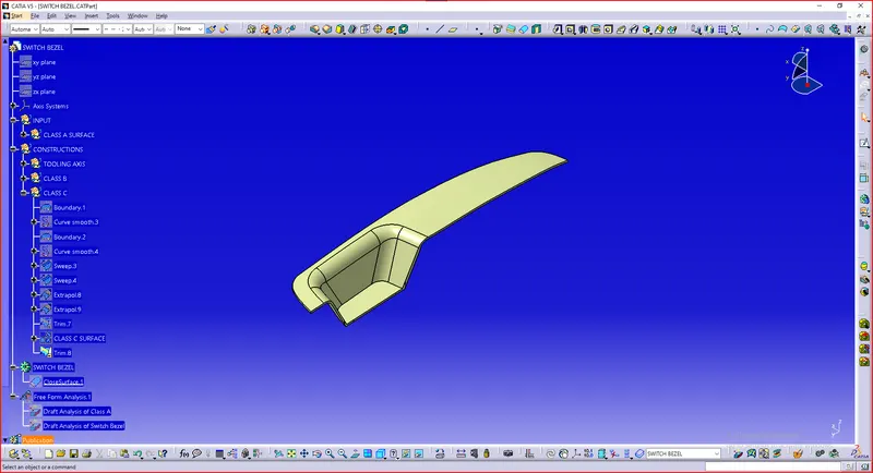
- Now Trim this Join surface with Class B surface.
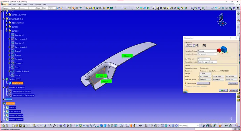
- Define Part Workbench. Use Close Surface tool to produce a solid body from the surface.
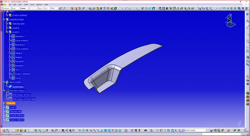
- Thickness 2.5mm
Draft Analysis of Solid Model:
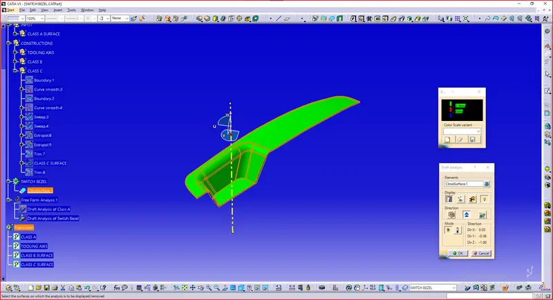
- Insert->Analysis->Draft Analysis
- Drag the Compass and align it with the Tooling axis
- Click on the Solid body and it will be differentiated with colors according to the Draft angle of the body with the tooling axis. If the colour is Green, the draft angle is more than 2.9 degrees and it will clear the tooling axis, if colour is Red, the draft angle is more than 0 degrees and less than 2.9 degrees, if colour is Blue, draft angle is less than 0 degrees and it won’t clear tooling axis and draft angle must be changed.
Draft Analysis of Switch Bezel
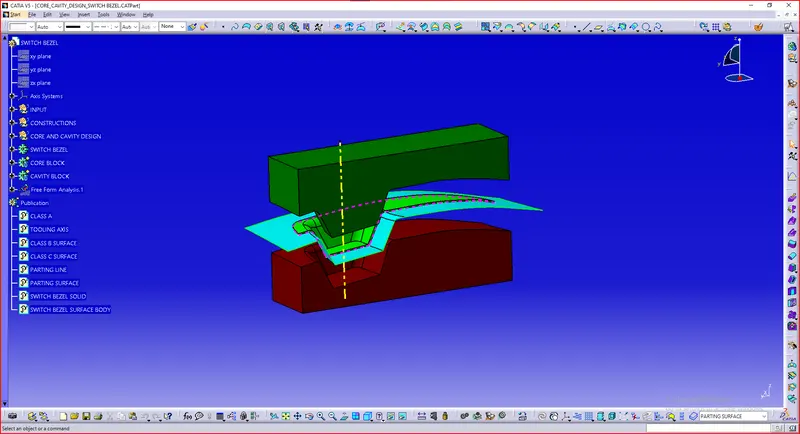
CORE & CAVITY DESIGN:
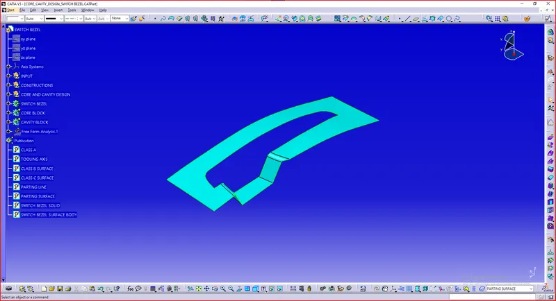
PARTING SURFACE
CORE
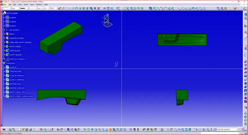
CAVITY
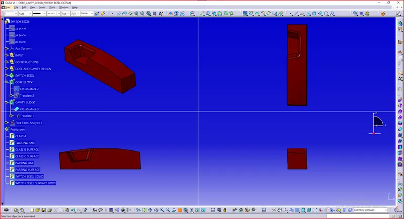
CORE, CAVITY AND SWITCH BEZEL
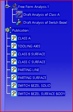
Publication:
Tools->Publication
Select Tooling axis, Class A, Class B, Class C surface, Parting line, Parting Surface, Switch Bezel Surface and Switch Bezel Solid Body and pick Publication from Tools tab below the title bar.

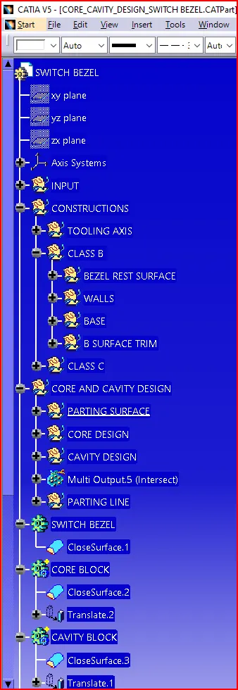
Tree Structure
CONCLUSION
- Tooling axis is created and Draft Analysis is done on Class A surface.
- Class B and Class C surfaces are developed and a Close surface is created.
- Draft analysis is done on Switch Bezel with a nominal draft angle of 2.9 degrees.
- Parting Surface is created.
- Core and Cavity parts are created.