Week -2
1. Simulink model of Doorbell
AIM: To create a Simulink model of Doorbell using solenoid block
Solenoid: A solenoid is a device comprised of a coil of wire, the housing, and a moveable plunger (armature). When an electrical current is introduced, a magnetic field forms around the coil which draws the plunger in. More simply, a solenoid converts electrical energy into mechanical work.
OBJECTIVE:
- To create Simulink model of doorbell
- Use close switch for two seconds and then releases
- To observe the physical movement of the plunger
BODY OF CONTENT:
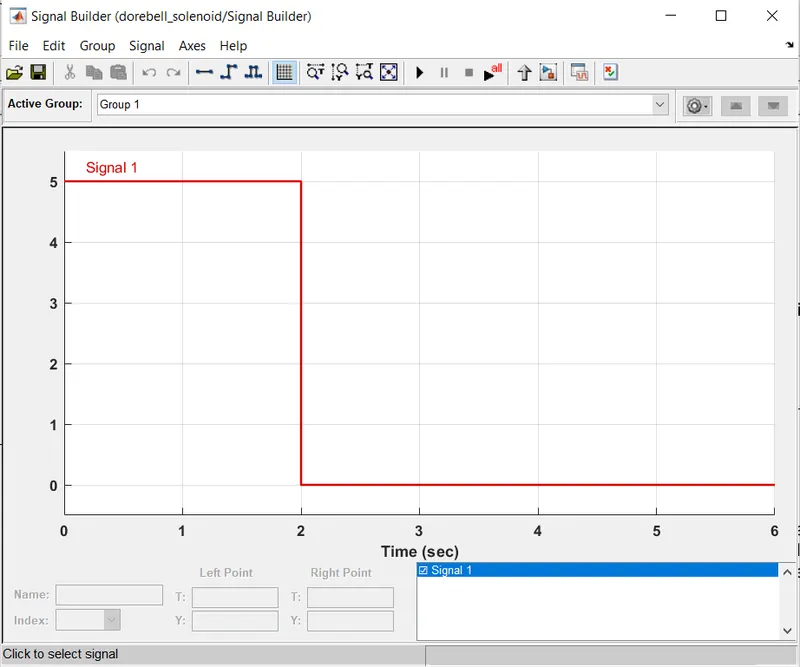
- Signal builder block is used to create the signal with variable amplitude for 6 seconds
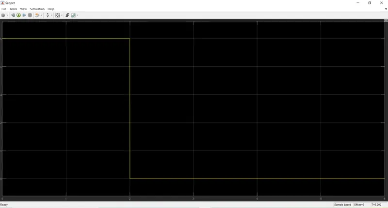
- In this signal, for initial two seconds the amplitude is 5mm and after two seconds the amplitude drops to zero
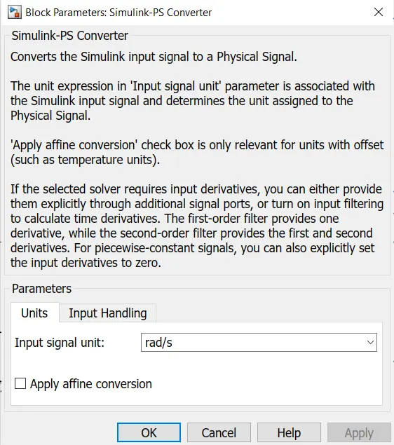
- Specifying the unit of the signal inside Simulink-PS converter block
- Specifying Units is necessary to obtain correct solution, in case if the next block uses some unit which is different from the input signal, that signal unit has to be converted before it is passed to the block
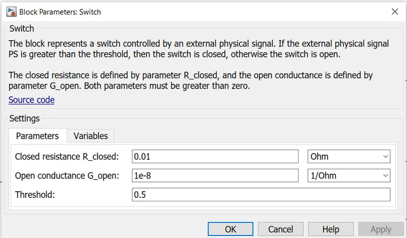
- The switch is used to create the situation where it is closed for two seconds and then released
- For first two seconds the amplitude is greater than threshold value so the switch will be closed and charge will be flowing in the circuit and after two seconds the amplitude drops to zero which is less than the threshold value, so the switch will be open and no charge will be flowing in the circuit
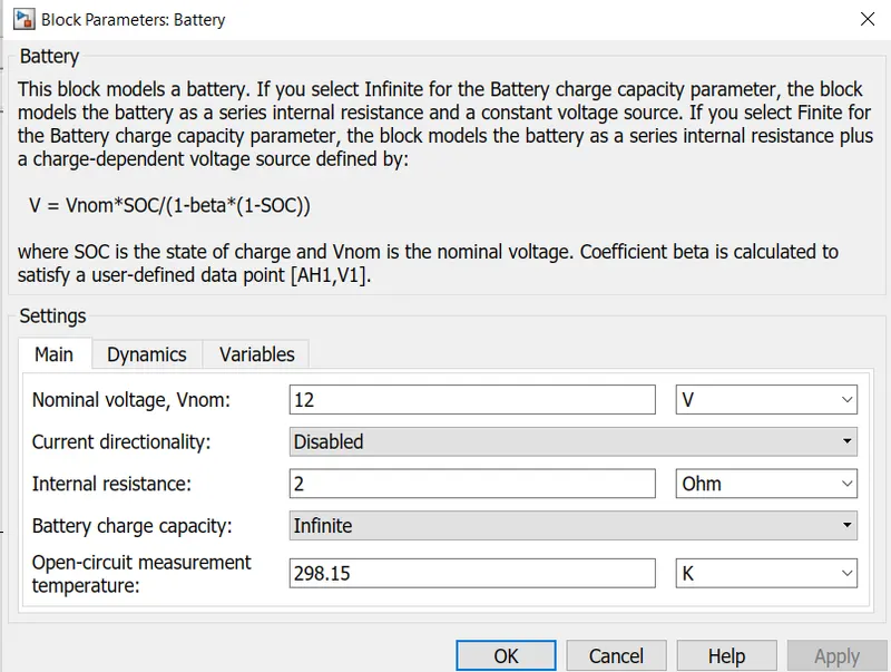
- The below figure shows the Battery block, where all parameters were kept default
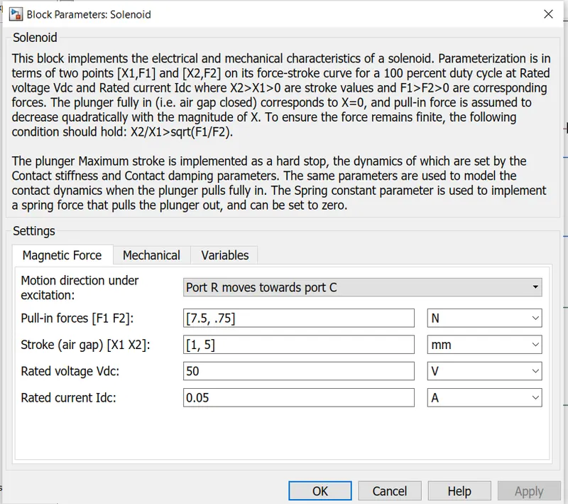
- Below figure shows the Solenoid block's Magnetic Force parameters
- Parameter-The Motion direction under exitation is selected for-Port R moves towards port C
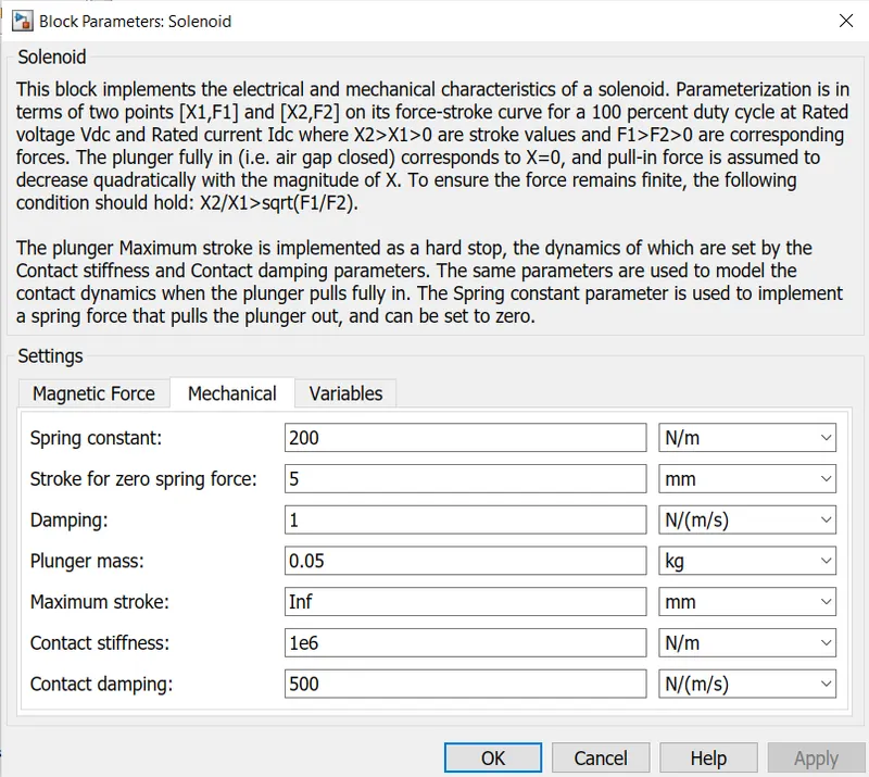
- Below figure shows the Solenoid block's Mechanical Parameters, where all the values are kept default
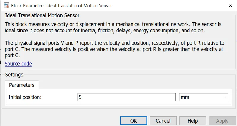
- The Ideal Translational Motion Sensor is used to measure the plunger displacement
- The Initial position of the plunger is set to 5mm from the C port
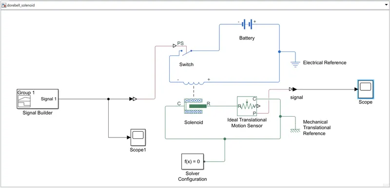
- Below figure shows the Simulink model of Dorebell
EXPLAINATION:
- The Signal Builder block is used to create a signal, where for initial two seconds the amplitude is 5mm and after two seconds the amplitude drops to 0mm for another 4 seconds
- The signal is observed using scope
- The Simulink-PS converter is used to input the signal to the Switch, which is part of electric circuit, other blocks in electric circuit are battery, Electrical Reference,and Solenoid
- The switch is closed for first 2 seconds as the threshold value is less than the signal amplitude and the charge flows through the circuit, and the magnetic field is generated due to the solenoid and the plunger starts to move and after 2 seconds the signal amplitude becomes less than threshold so the switch become open, stopping the flow of charge
- The Solenoid block has two ports R(plunger) and C(case) other than +ve and -ve charge ports
- The C port is connected to theMechanical Translational Reference and R port is connected to the R port of Ideal Translational Motion Sensor block
- The Ideal Translational Motion Sensor block is connected to the Solenoid to measure the plunger displacement
- This block has four ports R, C, V, and, P which are Rod, Case, Velocity, and Position respectively
- The PS-Simulink converter is used to convert the physical signal from the sensor block and input the converted signal to the scope to obtain the position of the plunger
RESULTS:
- Scope output of the signal from Signal Builder block, showing the signal curve, for initial 2 seconds the amplitude is 5mm and after 2 seconds the amplitude drops to 0
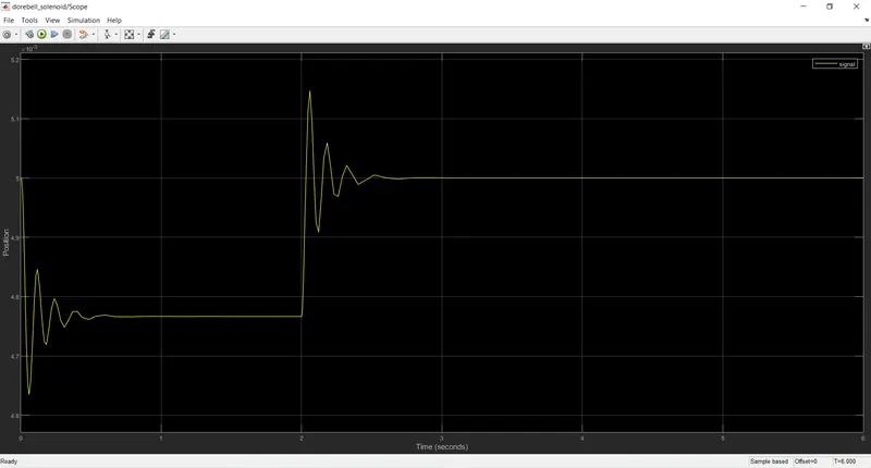
- Scope output of the Ideal Translational Motion Sensor, showing the displacement of the plunger, from 0 to 2 seconds there is plunger movement and then after 2 seconds the plunger movement comes to rest
CONCLUSION: The Simulink model of Dorebell is created and the plunger movement is observed. The Signal Builder block is used to create the signal which would keep the switch closed for 2 seconds and open the switch after 2 seconds, so in the initial 2 seconds the circuit will be closed and charge flows across the solenoid and the plunger moves, the plunger movement is measured using the motion sensor and obtained its position using the scope
REFERENCES:
- https://youtu.be/BbmocfETTFo
- https://www.mathworks.com/help/releases/R2021a/physmod/sps/ref/solenoid.html?s_tid=doc_srchtitle
- https://www.tlxtech.com/articles/solenoid-101-what-is-a-solenoid
2. Simulink model of Fan controlled by Temperature
AIM: To Model a system which uses a thermistor to sense the temperature of a heater to turn on or turn off the fan
GIVEN:
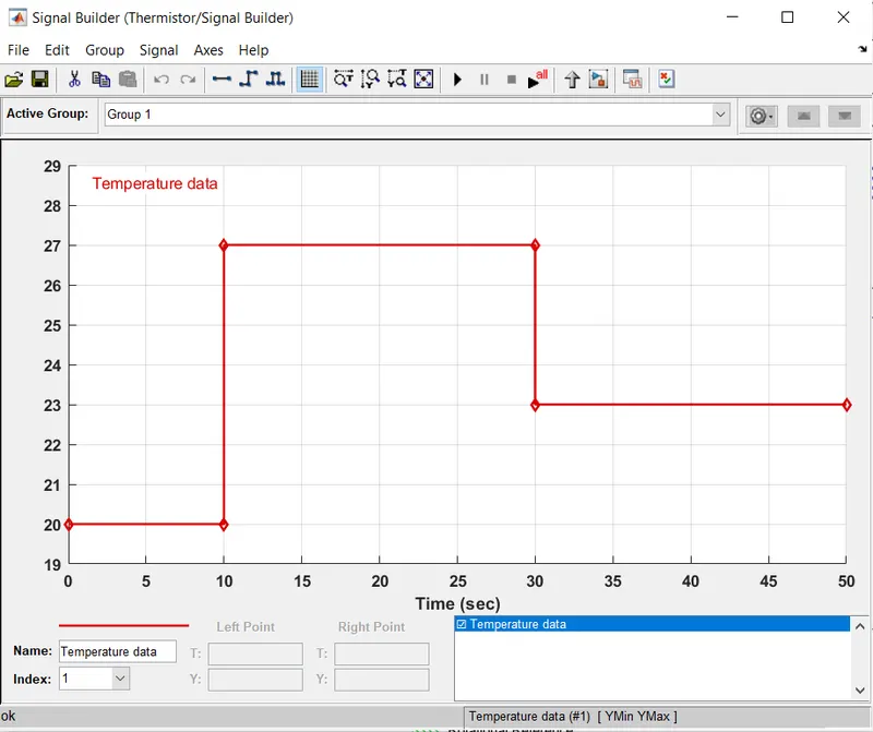
- Temperature source: 20 degC from 0 to 10 secs, 27 degC from 10 to 30 secs, 23 degC from 30 to 50 secs
- Fan conditions: ON if the temperature above 25 degC, OFF otherwise
OBJECTIVE: Use thermistor to sense temperature and control the DC motor output
- Thermistor: The Thermistor is a special type of variable resistive element that changes its physical resistance when exposed to changes in temperature. The working principle of a thermistor is that its resistance is dependent on its temperature.
BODY OF CONTENT:
- Signal Builder block is used to create a signal according to given conditions
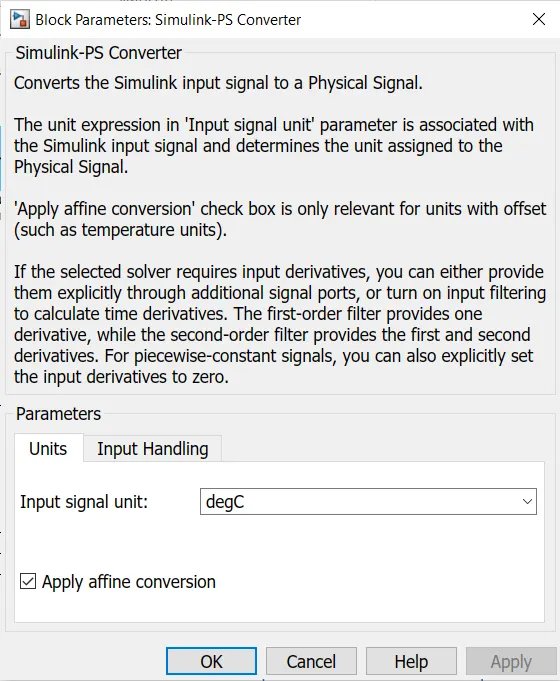
- Below figure shows specifying the unit of the input signal. As the given temperature is in degC and we used same while creating signal, we should specify the units used in Simulink-PS Converter parameters block, which will remove the error which may occur if the next block will be acccepting the signal in some other units
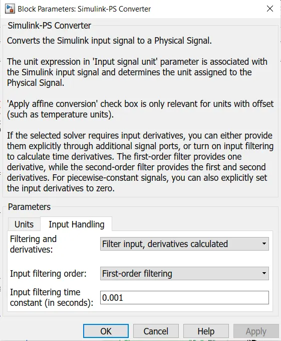
- Below figure shows the input handling Parameters block of Simulink-PS converter where the parameter - 'Filtering and derivatives' is selected to 'Filter input, derivatives calculated' and parameter - 'Input filtering order' is selected to 'First-order filtering'. These parameters are changed due the error showing 'not enough input derivatives were provided for one or more Simulink-PS converter', this is due the solver type requiring fewer input derivatives to solve the model.
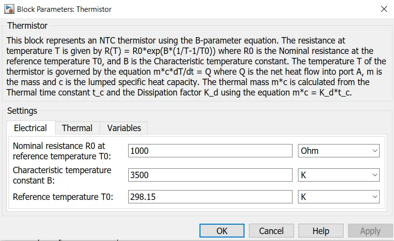
- Below figure shows the parameters block of Thermistor with Negative Temperature Coefficient, where the electrical parameters are kept constant. Thermistor converts the unit of temperature from degC to K
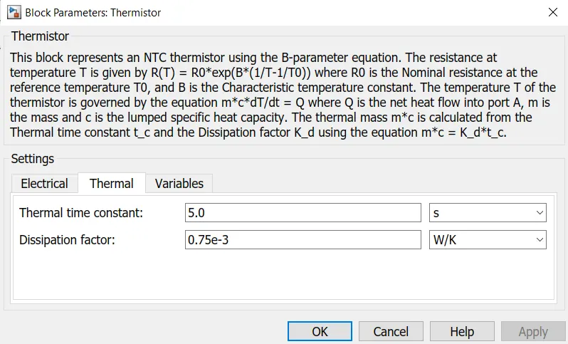
- Below figure shows the parameters block of Thermistor with Negative Temperature Coefficient, where the thermal parameters are kept constant
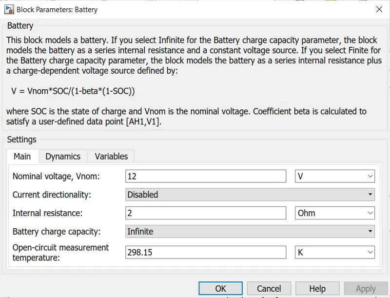
- Below figure shows the Battery parameter block where all the parameters are kept default
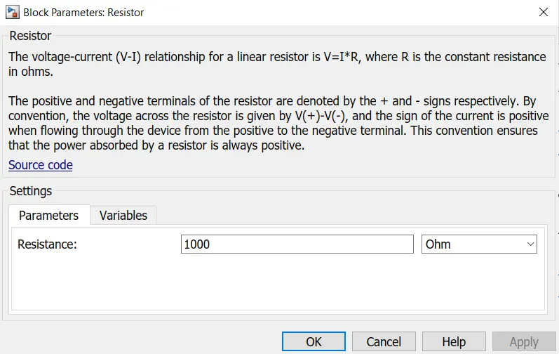
- Below figure shows the parameters of Resistor block, where the Resistance value is changed to 1000 ohm
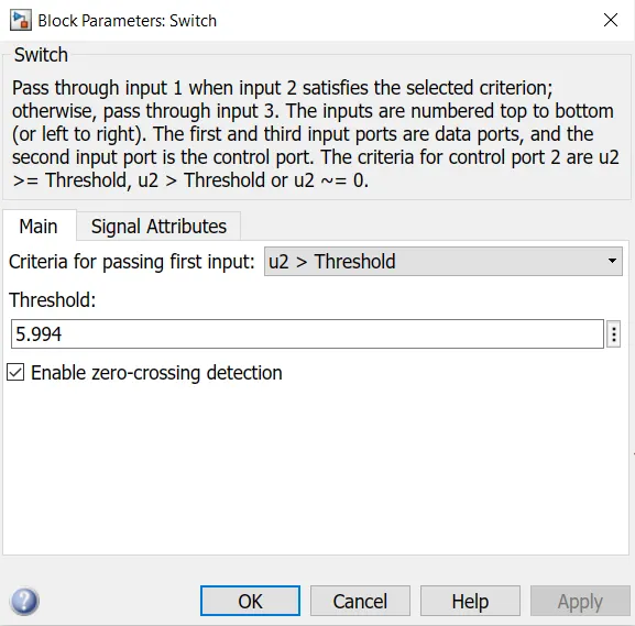
- Below figure shows the Parameters of the Switch block which receives the input signal from voltage sensor, and the parameter - 'Criteria for passsing first input' is selected to - 'u2>Threshold', which would make sense according to the condition provided. The Threshold value is also changed to the value of voltage at 25 degC, which is 5.994. If the input signal value is greater than the threshold value than that signal will pass through and if the input signal value is less than the threshold value it will not pass through, instead a 0 value will be passed from the third port provided by the constant block
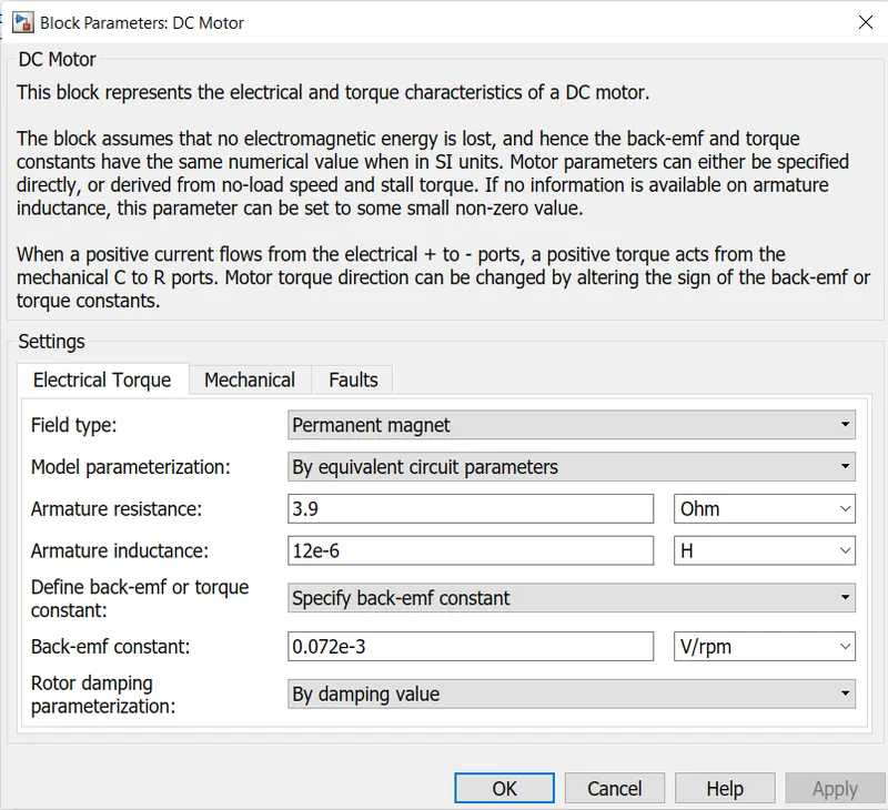
- Below figure shows the parameters block of DC Motor, where the Electrical Torque parameters are all used default
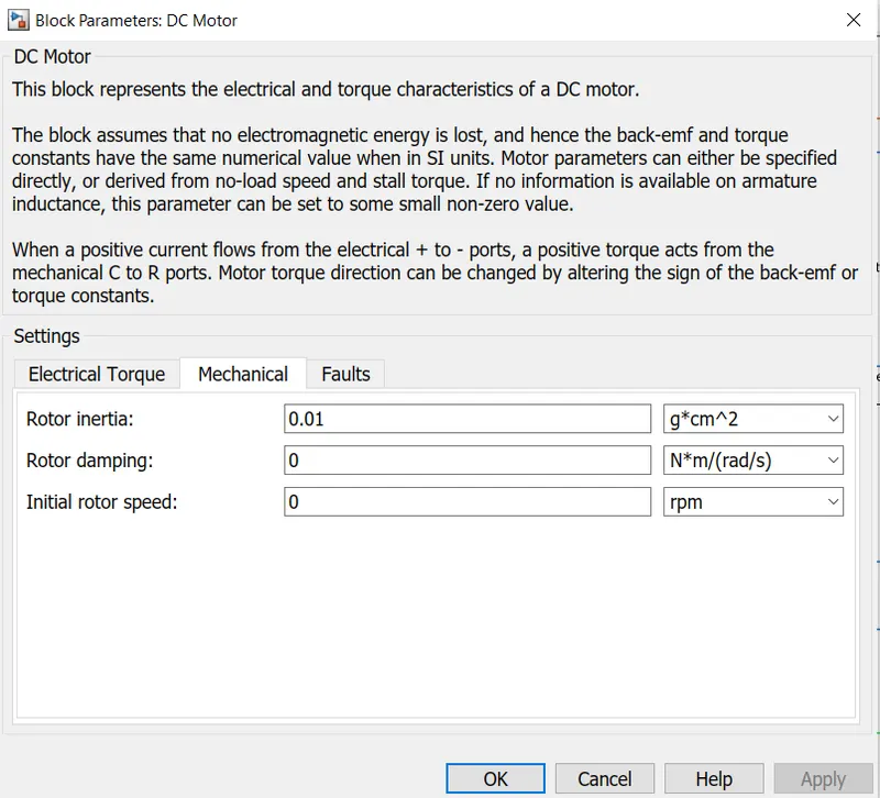
- Below figure shows the parameters block of DC Motor, where the Mechanical parameters are all used default
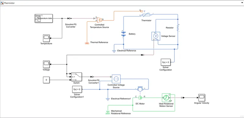
- Below figure shows the simulink model of fan which is turned on and turned off depending upon the temperature sensed by the thermistor and the Angular Velocity of the fan is recorded for given time period of 50 secs
EXPLANATION:
- To create a signal according to the given condition the Signal Builder block is used and then the signal is passed to Controlled Temperature Source through the Simulink-PS Converter, which converts the Simulink signal to Physical signal and this block is also used to assign units for the signal
- The Controlled Temperature Source usually stores the temperature in Kelvin units, so in order to get correct solution the input signal should be in Kelvin or the units should be specified so that convertion could be done in the Controlled Temperature Source
- The output of Signal Builder is observed using scope
- The output signal from Controlled Temperature Source is passed to Thermistor which is connected in a electrical circuit which has other elements including Resistor, Battery, Electrical Reference, Voltage Sensor, and Solver Configuration
- The resistance was changed to 1000 ohm inside the Resistor block, although it is not necessery for this model
- The voltage sensor is connected parallel to the resistor and the voltage is observed across the resistor through the scope
- To impliment the condition according to which the fan would be controlled, a Switch block is used with three input port where first port is data port which is passed with the output signal from the Voltage sensor, the second port is passed with with the same signal as passed with the first port but with the condition that if the signal value is greater than the Threshold value then only the signal from port one could be passed as an output from switch, if the signal value at second port is less than the threshold value, it will be blocked and the signal from third port will be outputed. Here in this model the third port is given value 0 using the constant block
- The output signal from the switch block is passed to Controlled Voltage Source which is connected in another electrical circuit which consists DC Motor, Electrical Reference and Solver Configuration
- The DC Motor block has other two ports excluding the charge ports, namely C(Motor Case) port and R(Motor Rotor) port
- The DC Motor is connected to the Mechanical circuit with its two ports C and R. The R port is connected to the R port of the Ideal Rotational Motion Sensor and C port of DC Motor is connected to the C port of the Ideal Rotational Motion Sensor and this closed circuit is connected with Mechanical Rotational Reference
- The Ideal Rotational Motion Sensor block has two output ports namely W(Angular Velocity) portand A(Angle) port. The output physical signal from the W port is converted into Simulink signal and it is observed using the scope block
RESULTS:
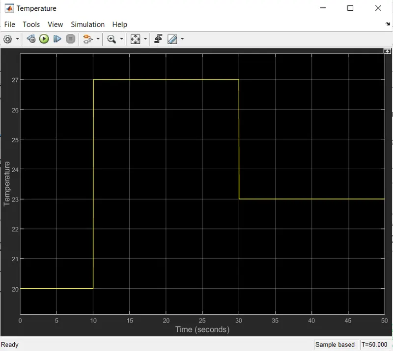
- The below figure shows the scope output contaning the signal from the Signal Builder block, which shows the signal which is a variable temperature over a time range of 50 secs. From 0 to 10 secs, temperature is 20 degC, from 10 to 30 secs, temperature is 27 degC and from 30 to 50 secs, temperature is 23 degC
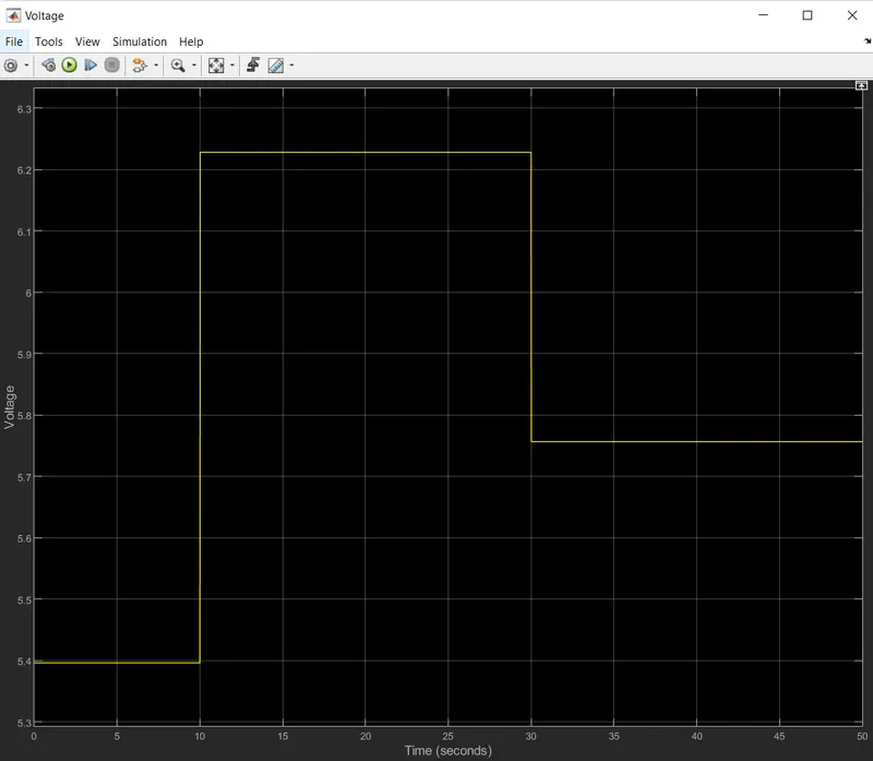
- The below figure shows the scope output containing the signal from the Voltage sensor, where 0 to 10 secs the voltage is 5.396V, from 10 to 30 secs the voltage is 6.228V and from 30 to 50 secs the voltage is 5.757V
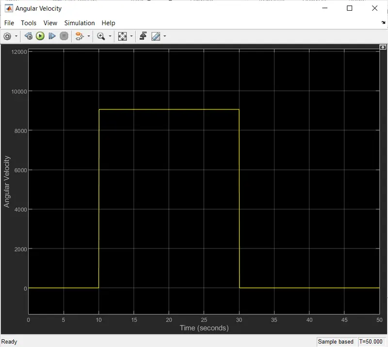
- The below figure shows the scope output containing signal from the Ideal Rotational Motion Sensor, which shows the angular velocity over a time period of 50 secs. From 0 to 10 secs the Angular Velocity is 0 rad/s, as in this period the temperature is below 25 degC and switch passes 0. From 10 to 30 secs the Angular Velocity is 9.058 rad/ms, as in this period the temperature raises above 25 degC and switch passes the voltage signal and from 30 to 50 secs the Angular Velocity drops to 0 rad/s over this time range as the temperature falls below 25 degC and the switch passes 0 value
CONCLUSION: Simulink model is created using Thermistor to sense the temperature and turn on and off the fan. To get the threshold value which is the voltage value at 25 degC, a different temperature signal is passed using the signal builder having the signal value of 25 degC and for this signal the voltage is observed and noted across the resistor. Once the voltage value at 25 degC is obtained, this value is passed as a threshold value inside the Switch block, and the main signal source is again changed according given conditions using the Signal Builder block
REFERENCES: