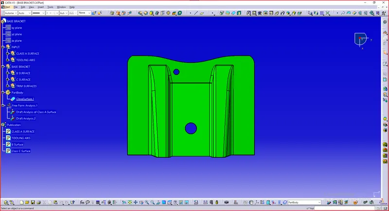
Week 8 - Challenge 2 - Base Bracket Design
BASE BRACKET DESIGN
PROCEDURE:
- Check if the class A surface is properly joined and has no discontinuity.
- For checking continuity use Join or Boundary command.
- Check for the suitable tooling direction. Usually, a perpendicular axis to large flat surface or hole is considered as a tooling axis.
From X direction the holes and slot cannot be cleared.
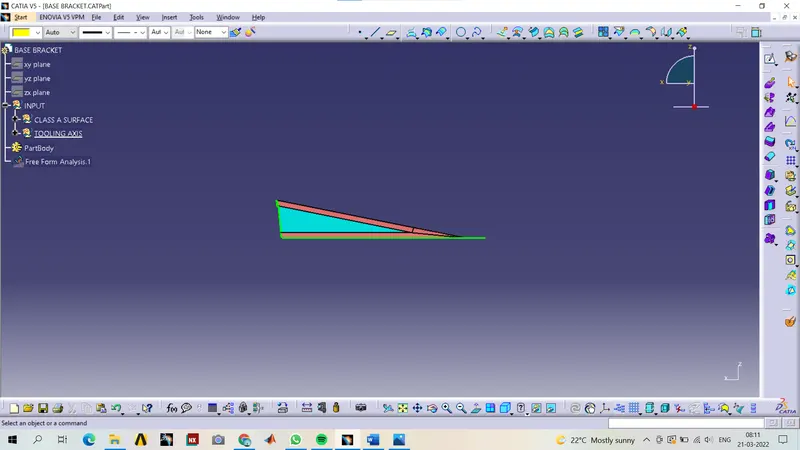
From Y direction only hole can be cleared.
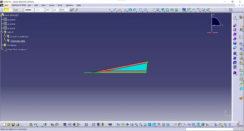
From Z direction all the features can be cleared, so create the dummy tooling axis along Z direction.
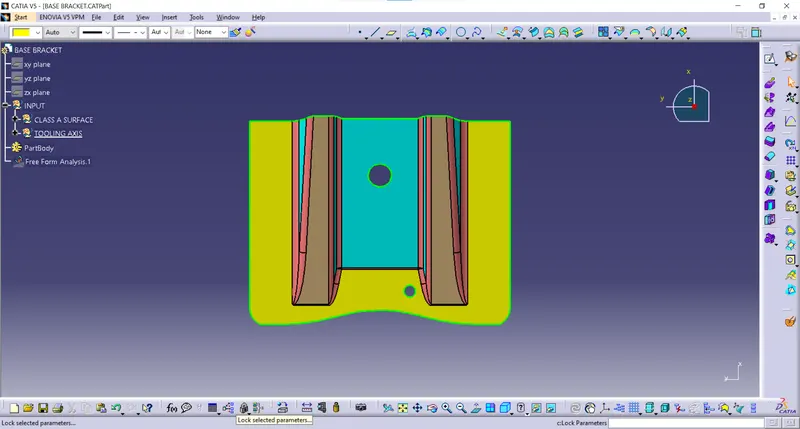
Dummy Tooling Axis
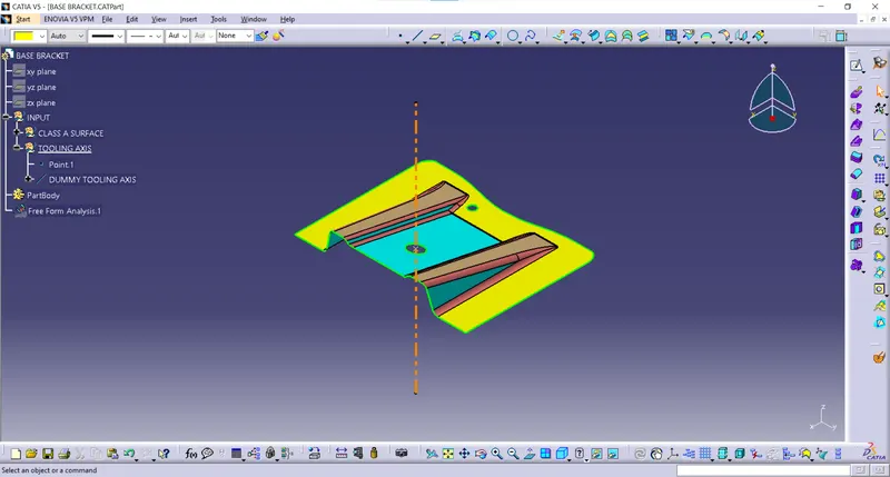
Tooling Axis creation:
- Another method of creating tooling axis is Bisecting method.
- Find the surfaces which would be difficult to be tooled. Create a plane and bisect it with the class A surface.
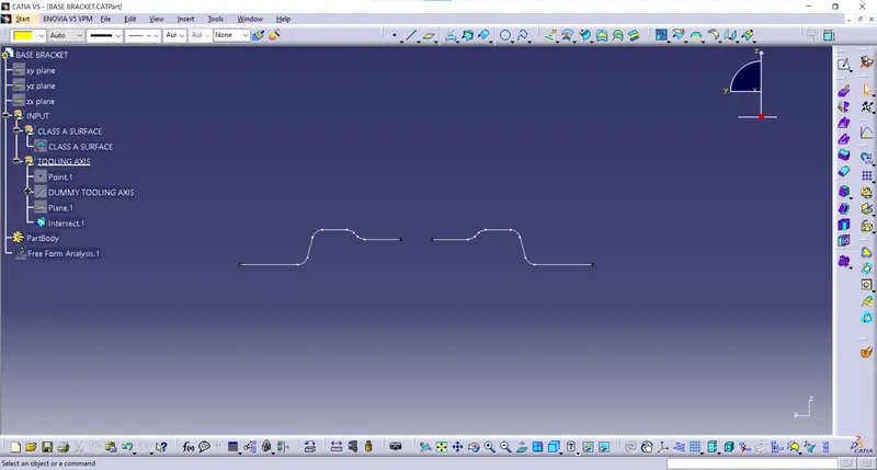
- Create lines using point to point method.
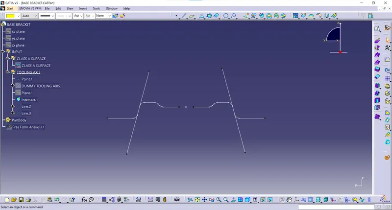
- Create a Tooling axis using bisecting method.
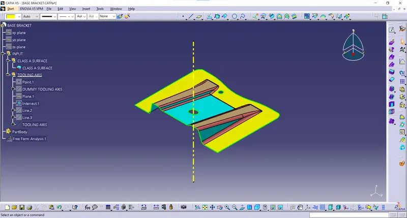
- Find the surfaces which would be difficult to be tooled. Create a plane and bisect it with the class A surface.
Draft Analysis of Class A Surface:
- Insert->Analysis->Feature Draft Analysis
- Drag the Compass and align it with the Tooling axis
- Click on the Class A surface and it will be differentiated with colours according to the Draft angle of the surface with the tooling axis. If the colour is Green, the draft angle is more than 3 degrees and it will clear the tooling axis, if colour is Red, the draft angle is more than 0 degrees and less than 3 degrees, if colour is Blue, draft angle is less than 0 degrees and it won’t clear tooling axis and draft angle must be changed.
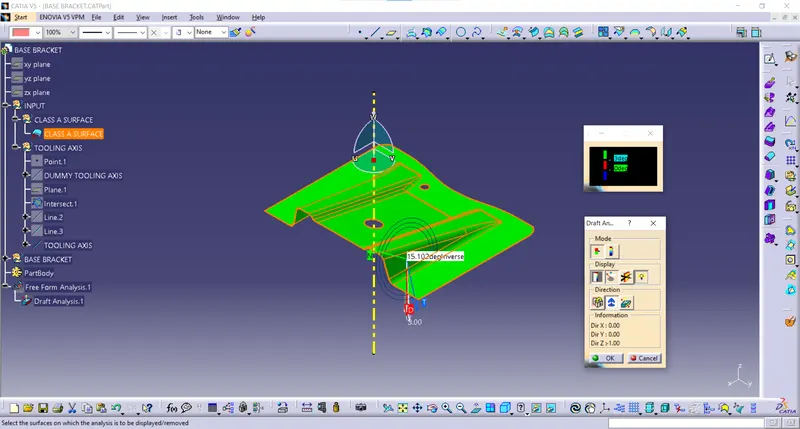
Class B Surface creation:
- Starting with the Ribs, extract Top and Side faces of ribs.
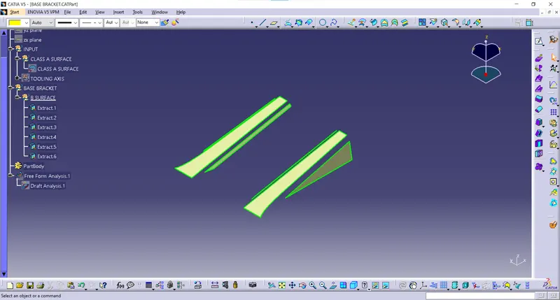
- After getting all faces, Untrim them.
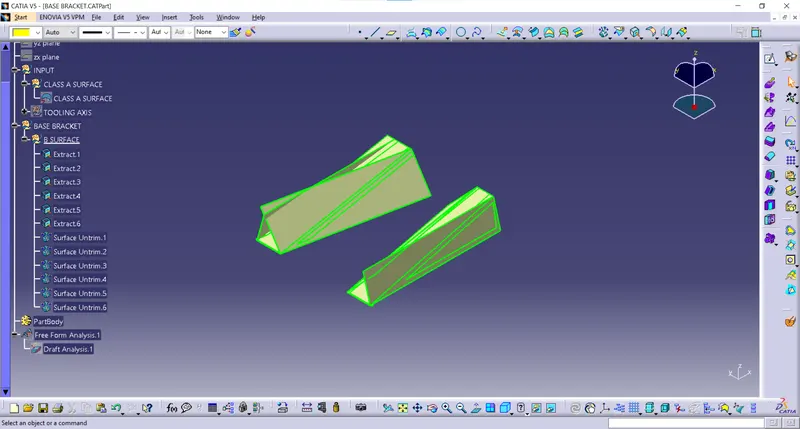
- Extrapolate all the Untrimmed faces.
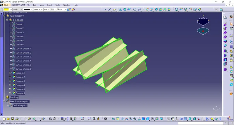
- Trim all the faces.
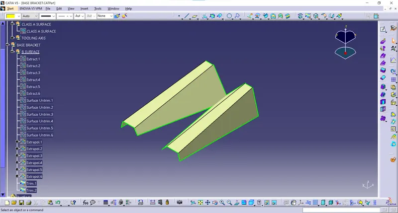
- Offset both ribs by 2.5mm, which is thickness of the component.
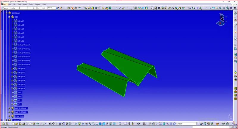
- Extract base surfaces.
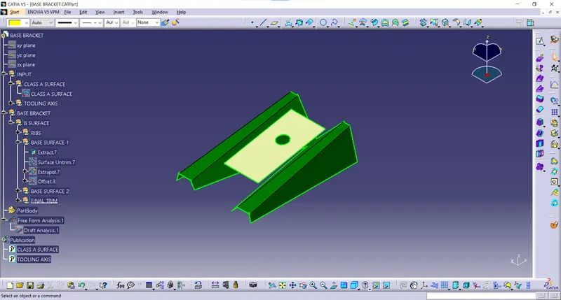
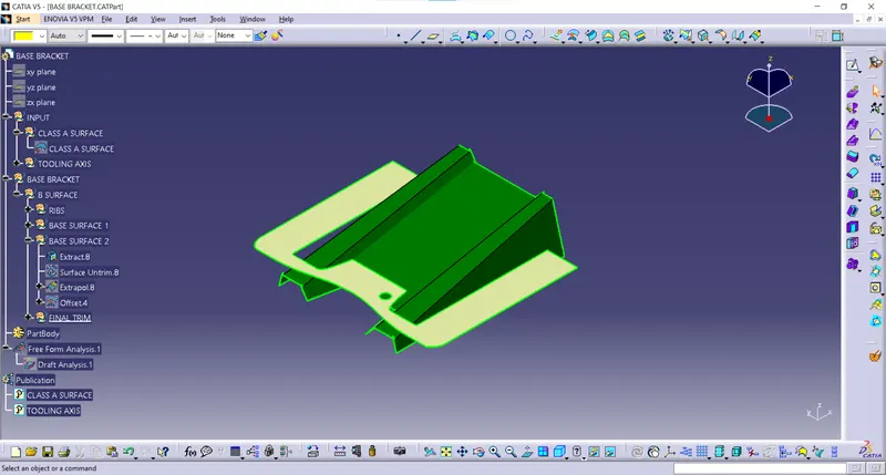
- Untrim them, then Extrapolate and Trim.
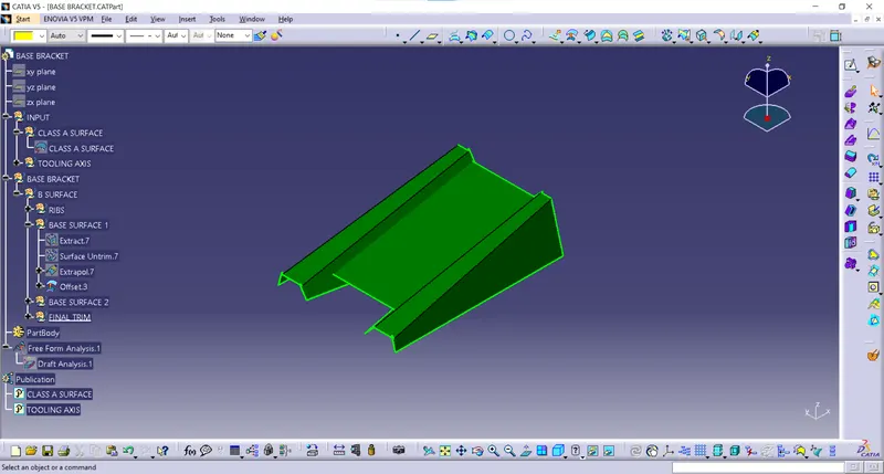
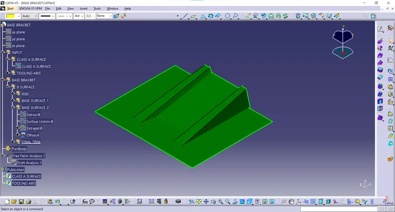
- Now Trim Ribs with Slant surface and this trimmed surface trim with Base surface. Now we got a final trim surface.
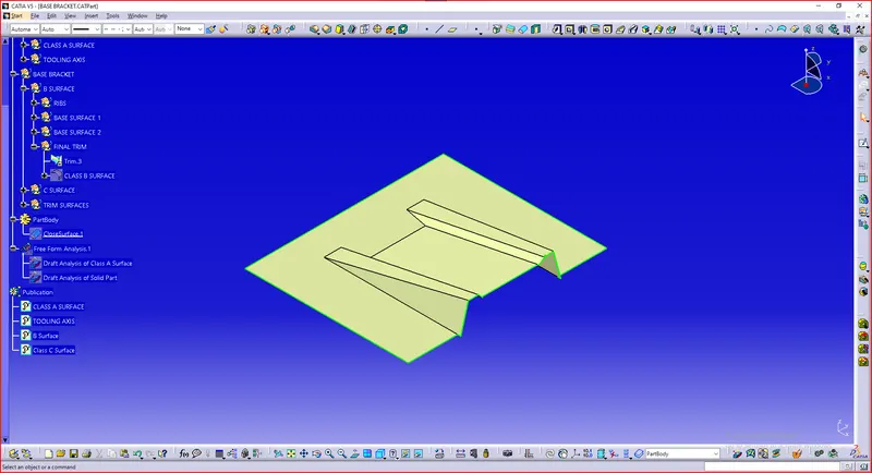
- Give Edge fillet of 5.5 mm to the edges. (Fillet radius + thickness)
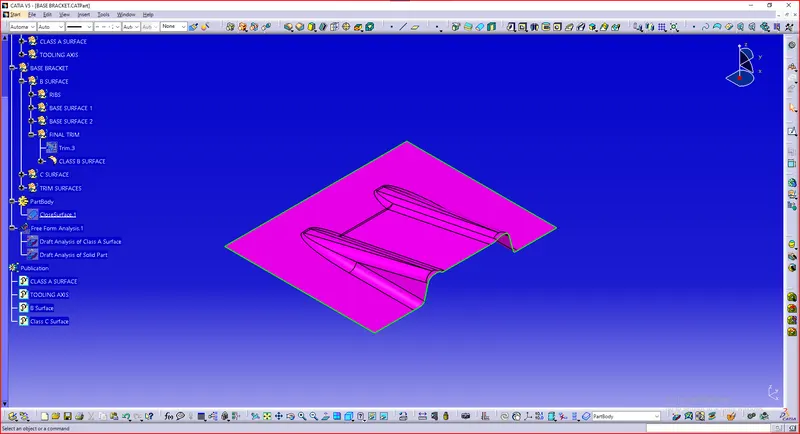
Class C Surface creation:
- Extract outside Boundary of the Class A surface.
- Sweep the Extracted Boundary using Tooling direction as the draft direction. Give 3mm Draft angle.
- Then extract the hole boundaries and Sweep with 3 degree draft angle.
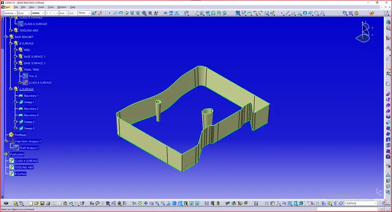
- Join Class A and Class C surfaces.
- Now Trim this Join surface with Class B surface.
- Define Part Workbench. Use Close Surface tool to produce a solid body from the surface.
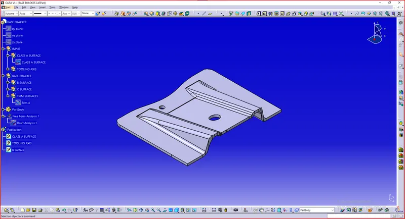
Draft Analysis of Solid Model:
- Insert->Analysis->Draft Analysis
- Drag the Compass and align it with the Tooling axis
- Click on theSolid body and it will be differentiated with colors according to the Draft angle of the body with the tooling axis. If the colour is Green, the draft angle is more than 3 degrees and it will clear the tooling axis, if colour is Red, the draft angle is more than 0 degrees and less than 3 degrees, if colour is Blue, draft angle is less than 0 degrees and it won’t clear tooling axis and draft angle must be changed.

Publication:
Tools->Publication
Select Tooling axis, Class A, Class B and Class C surface and select Publication from Tools option in the tools bar.
TREE STRUCTURE:
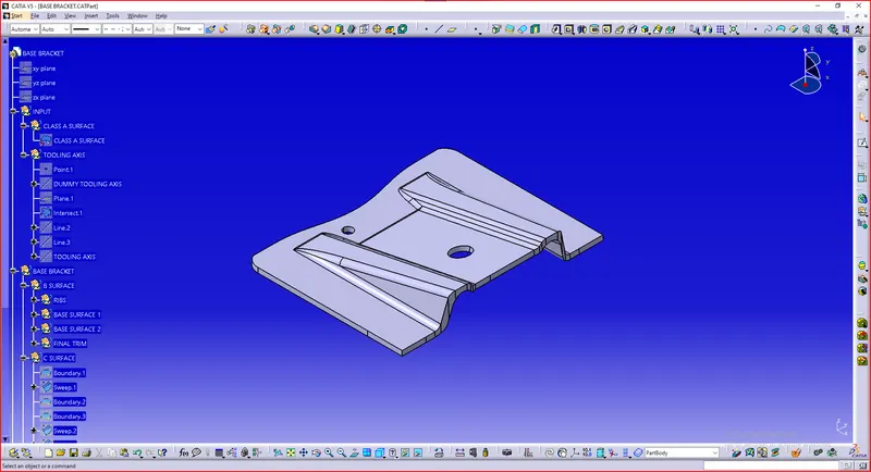
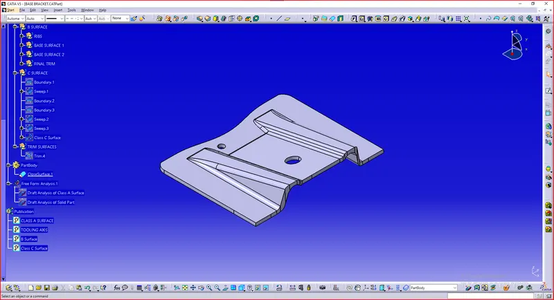
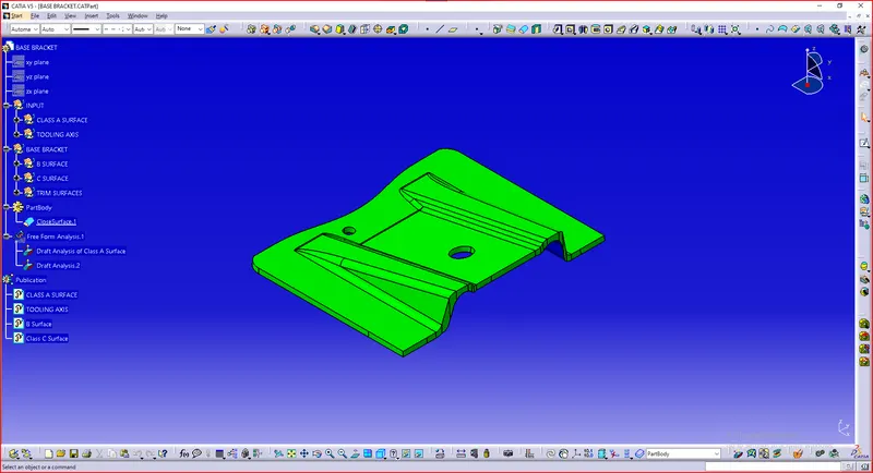
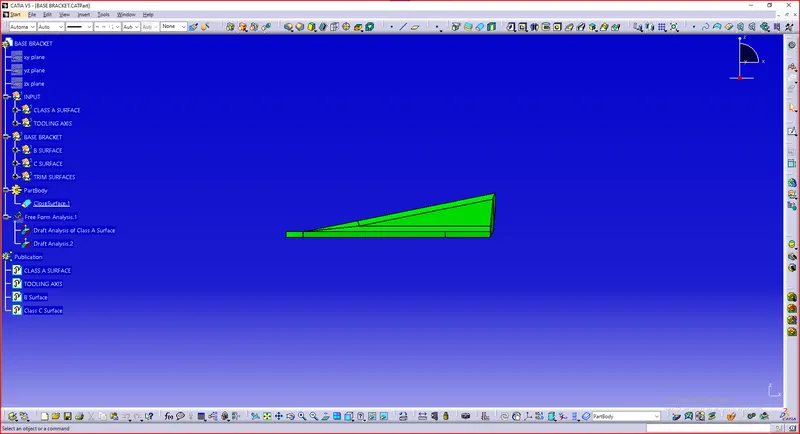
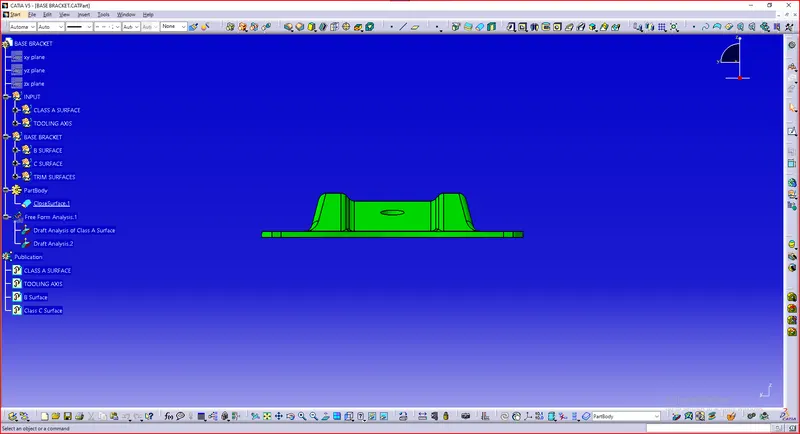
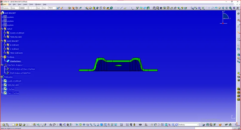
ORIENTATION:
ISOMETRIC VIEW
FRONT VIEW
LEFT SIDE VIEW
RIGHT SIDE VIEW
TOP VIEW