Week 4.2: Project - Transient simulation of flow over a throttle body
Aim: To set up and simulate the Transient simulation of flow over the throttle body.
Objective:
- Setting up Transient state simulation for flow over a throttle body.
- To generate the mesh that gives more accurate results.
- Post-processing the obtained results using ParaView and showing pressure and velocity contour.
Description:
A throttle is a mechanism by which fluid flow is managed by constriction or obstruction. The throttle is a means of controlling an engine's power by regulating the amount of fuel or air entering the engine. The throttle lever acts as a direct mechanical linkage. The butterfly valve of the throttle is operated by means of an arm piece, loaded by spring. This arm is usually directly linked to the accelerator cable and operates in accordance with the driver, who hits it. The further the pedal is pushed, the wider the throttle valve opens.
The main function of a throttle body assembly is to control the airflow into the engine based on vehicle demand. The throttle body is mounted between the air cleaner and the intake manifold. Following the angle of the throttle valve (butterfly valve) changes, it restricts the amount of airflow into the engine cylinder.
It has a venturi to reduce the pressure of the air flowing through it. The intake flow is throttled by reducing the flow area. This is done by providing a circular shaft known as a throttle shaft and is mounted with a butterfly valve downstream of the venture. The main challenge is the change in throttle position during transient operation of the engine, which introduces additional problems as the butterfly position is frequently changed as per the driver’s demand. The airflow can be considered unaffected by the fuel flow. However, the reverse is not true and fuel flow strongly depends upon the airflow. The schematic of a throttle body assembly describing the airflow path. Filtered air enters the throttle body and moves downstream. A butterfly valve (or throttle valve), restricts the amount of airflow into the engine based on the accelerator position.
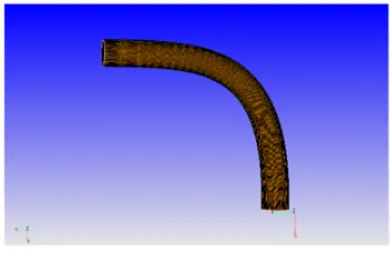
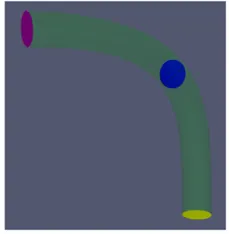
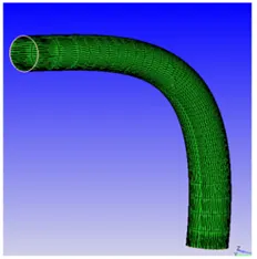
Geometry:
Simulation Case setup:
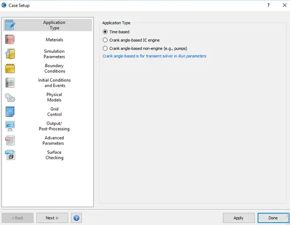
- Application type: Time based
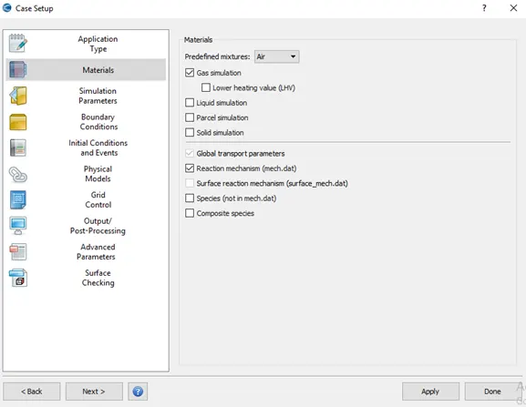
- Materials:
Predefined mixtures = Air
- Simulation Parameters:
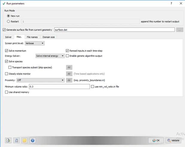
In Run Parameters two main things to be considered:-
(a) select the following solver settings
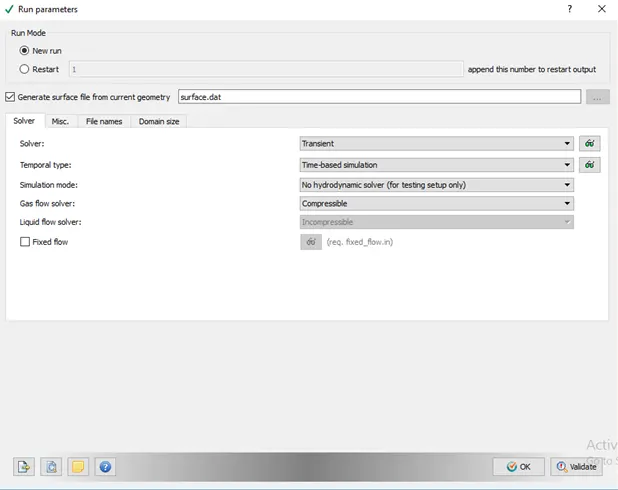
(b.) Go to Misc. > uncheck UseSharedMemory and uncheck Steady-State Monitor.
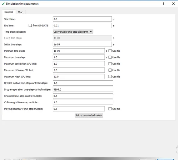
- Simulation Time Parameters:
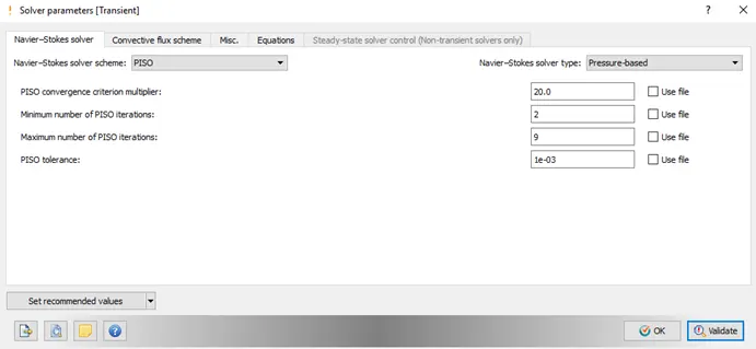
- Solver Parameters [Transient-State]:
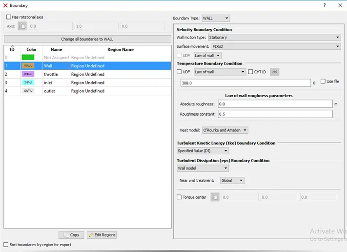
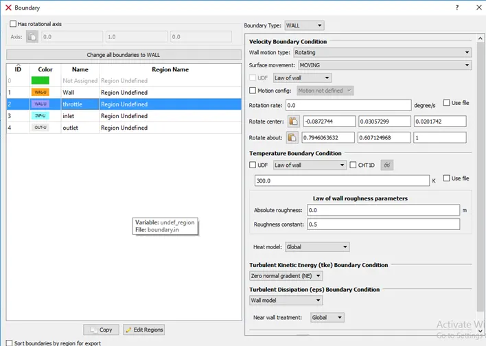
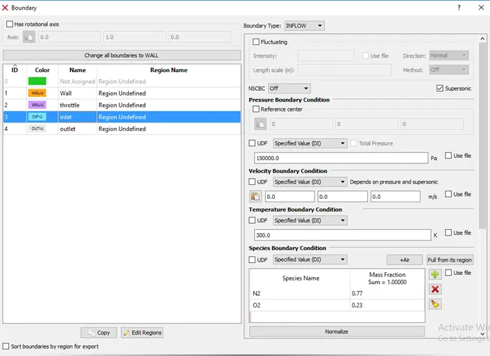
- Boundary Conditions:
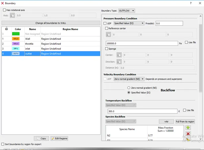
- Regions and Initialization:
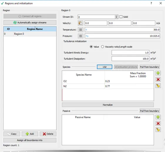
- Physical Models:
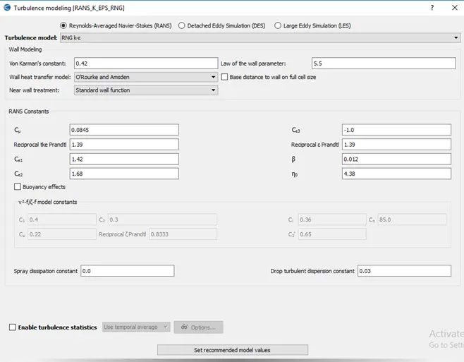
Click on Physical Models and select Turbulence Modeling in this case.
- Turbulence modeling:
- Grid Control:
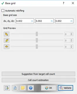
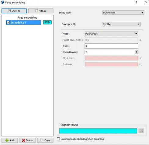
- Now click on Grid Control > select Fixed embedding.
- Post-Processing:
Post Variable Selection:
Click on Typical Variables/Geometry > Select required variables.
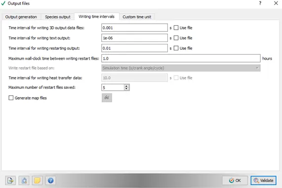
- Output Files:
Results:
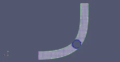
- Grid mesh (size: dx = 0.002, dy = 0.002, dz = 0.002)
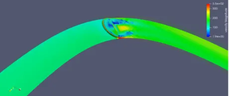
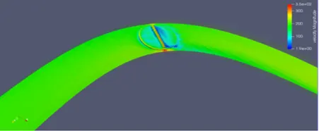
- Velocity Contour:
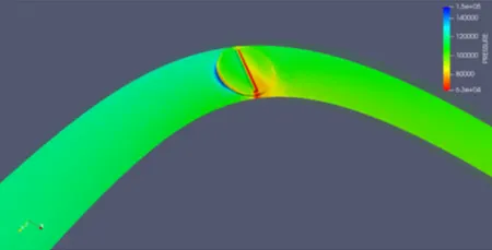
- Pressure Contour:
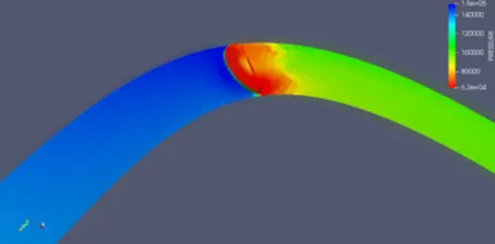
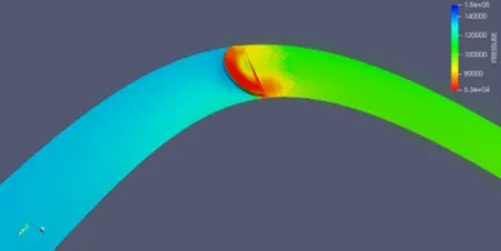
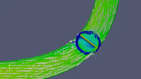
- Velocity Vector:
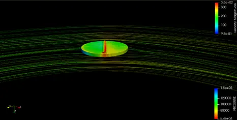
- Velocity Streamlines over the throttle valve:
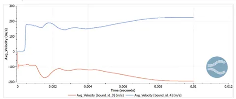
- Velocity Plot:
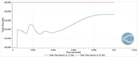
- Total pressure:
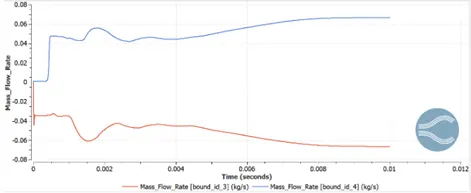
- Mass flow rate:
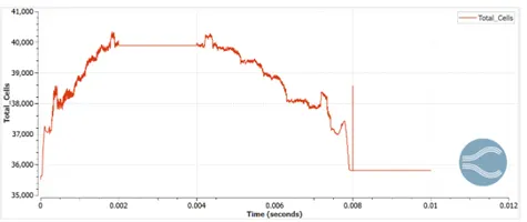
- Total Cell count:
Results:
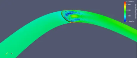
- From the above contours, it is clear that on giving the fine mesh to the valve the contours appear more details and the results are highly accurate.
- The flow through the throttle position is more accurate as the mesh generated along the throttle position is refined (having more cells surrounding the valve) i.e. by providing 2 embedded layers and scaling of 3 to the mesh.
- The contours show that there is a restriction to the flow of intake air that is caused by the throttle plate. The inflow mass flow rate is balanced by the outflow rate.
- If there is less restriction in the flow, then there is a lower loss in energy. Hence because of this the velocity at the outlet increases.
- As we have a moving mesh, the number of cells generated is more and hence simulation time is high.
Conclusion:
- The transient simulation flow over a throttle body is performed using converge CFD.
- With the finer refinement of mesh, accurate results are obtained. Various plots, contours, and animations are generated to study the flow over a throttle body.
- Throttle movement is also captured for a better understanding of flow.