Week-6 : Turbocharger Modelling
Aim:
Turbocharger Modelling using GT POWER
Objective:
- List down different TC and locate examples from GT Power
- Explore tutorial number 6 and 7
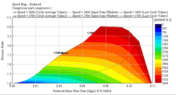
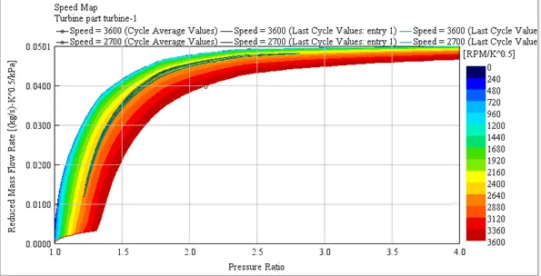
- Plot operating points on compressor and turbine maps
- In which application Variable Geometry Turbine is beneficial?
- Explore example- Diesel VGT EGR and understand the modeling part
Theory:
A turbocharger is a compressor that takes energy from the exhaust kinetic energy of the engine, makes it usable with the help of a turbine, and uses this energy for the action of compression of ambient air. When the compressor directly takes energy from the engine for compression, then it is termed a supercharger.
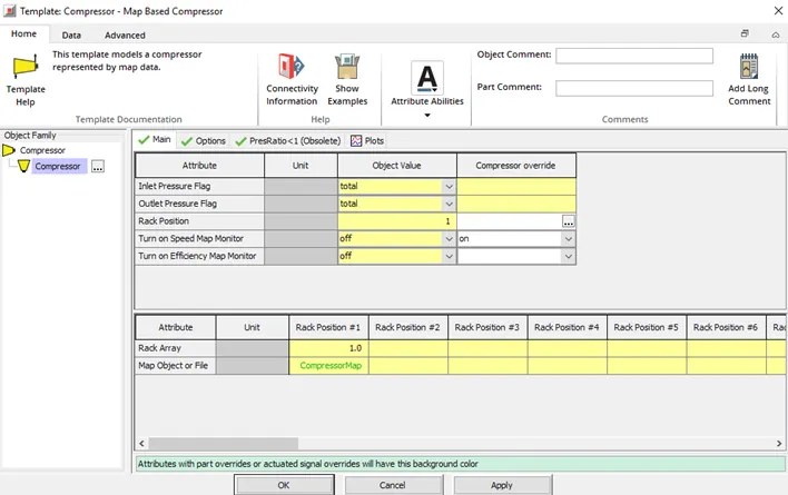
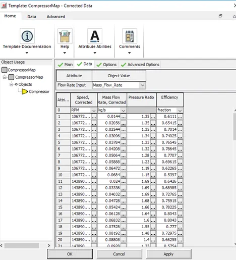
In GT-Power, we define the compressor and turbine object with reference temperature and pressure. To supply compressor/turbine data in GT, a standard SAE data file can be input. This standard SAE data file will be given by the supplier. Also, every compressor/ turbine has a performance chart data also called a compressor map or turbine map which has parameters such as RPM, Mass flow rate, Pressure ratio, and efficiency. This performance chart should also be given as input. This data as well is given by the supplier.
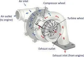
1. List down different TC and locate examples from GT Power
There are three types of Turbochargers that are used for practical purposes.
- Fixed geometry Turbocharger
- Wastegate turbocharger
- Variable Geometry Turbocharger or VGT
Fixed Geometry Turbocharger:
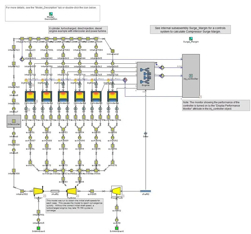
This is a form of turbocharger whose geometry is fixed. We cannot control the geometry and speed of the turbine or compressor of this turbocharger which makes it prone to mechanical failure at a very higher speed.
In the simplest turbocharger design, the turbine and compressor geometry is fixed and the boost pressure is entirely determined by the exhaust flow.
Wastegate turbocharger:
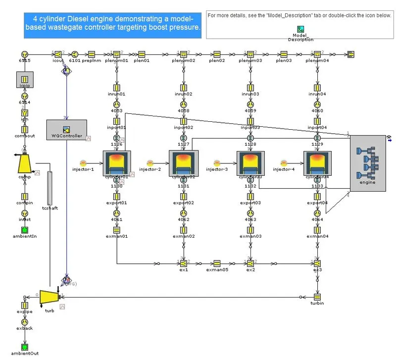
The wastage is the amount of exhaust gas which is going turbine is controlled by a small opening is known as wastage. Due to this mechanism, the speed of the turbine can be controlled and hence can be prevented from mechanical failure.
This technology helps to deliver optimum engine performance during peak operating conditions. In addition, the wastegate valve prevents the turbocharger from over-running. Particularly, it also avoids the engine from over-boost and prevents any mechanical failure.
Variable Geometry Turbocharger or VGT:
There are vanes around the turbine entry which control the number of exhaust gases entering the turbine inlet. So in that way, we can control the rpm of the turbine and hence the compressor. This is the most advanced version of the turbocharger and hence the most costly.
Variable-geometry turbochargers (VGTs), occasionally known as variable-nozzle turbines (VNTs), are a type of turbochargers, usually designed to allow the effective aspect ratio of the turbocharger to be altered as conditions change. This is done because the optimum aspect ratio at low engine speeds is very different from that at high engine speeds.
2. Explore tutorial number 6 and 7
- Tutorial 6
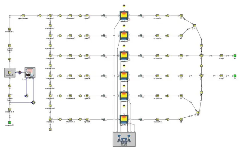
Boundary conditions:
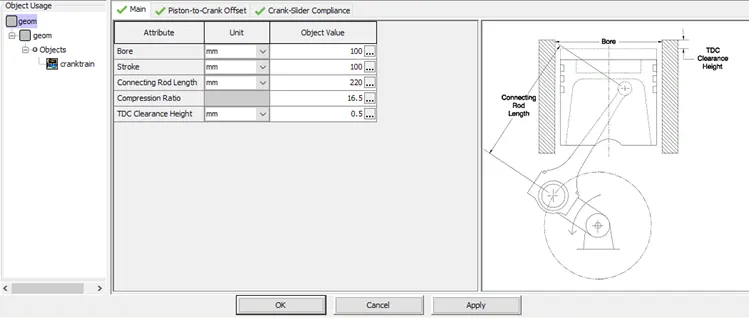
Engine boundary condition
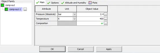
Inlet
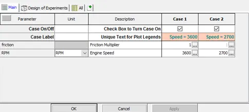
Case Setup
Run Setup
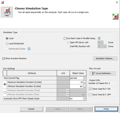
Results:
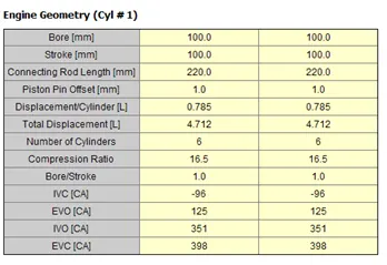
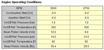
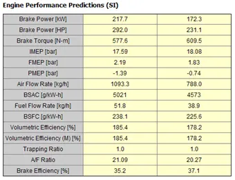
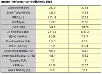
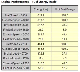
- Tutorial 7
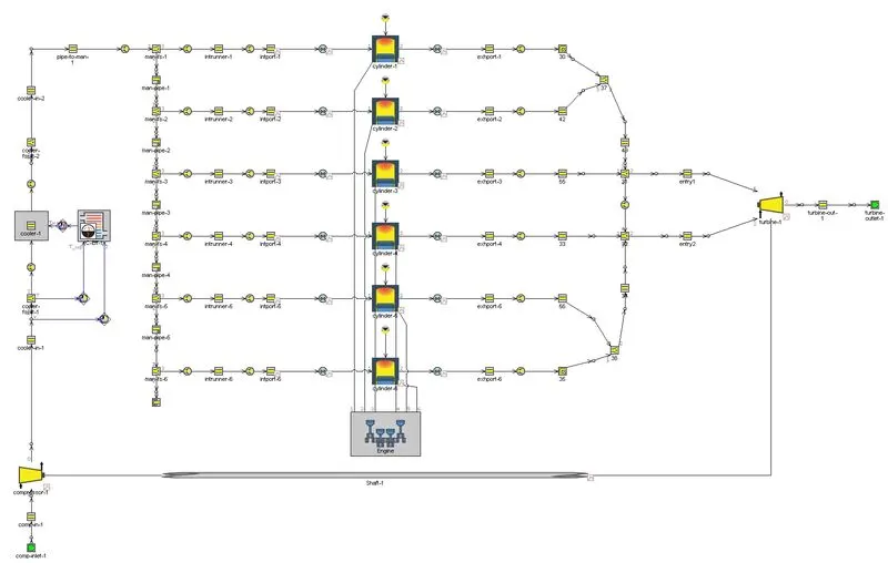
Boundary conditions:
Engine boundary condition
Inlet
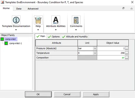
Compressor setup
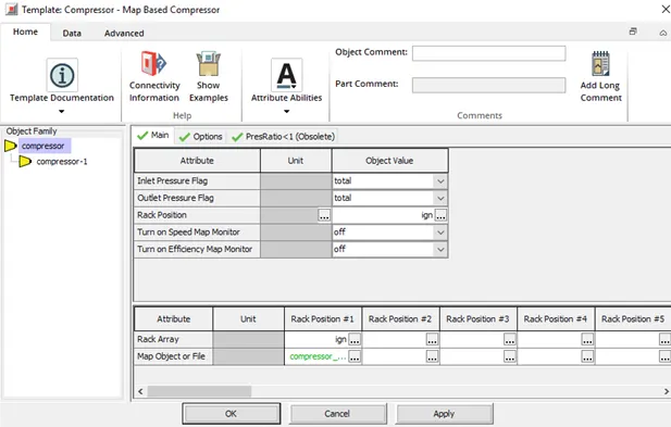
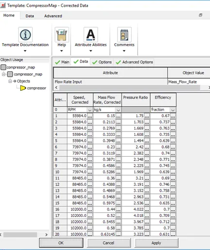
Turbine setup
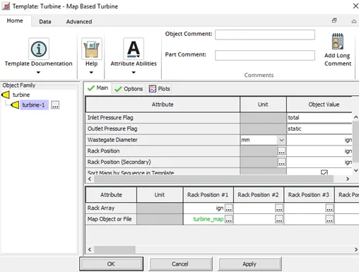
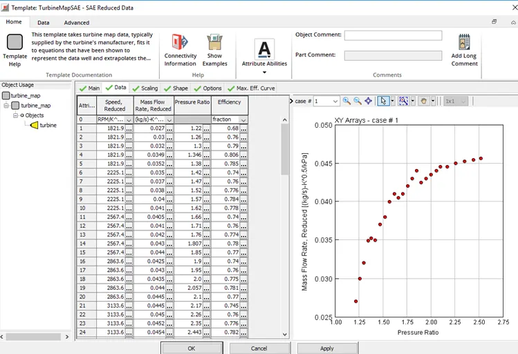
Case Setup
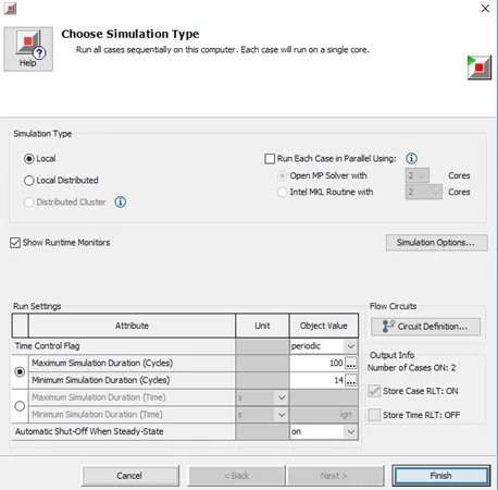
Run Setup
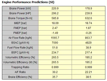
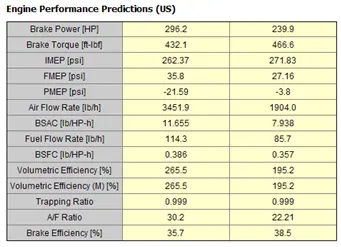
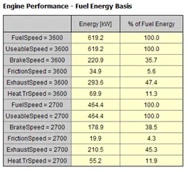
Results:
3. Plot operating points on compressor and turbine maps
- Compressor
- Turbine
4. In which application Variable Geometry Turbine is beneficial?
- VGT devices are designed to increase boost pressure at low speeds, reduce response times, increase available torque, decrease the boost at high engine speeds to prevent over-boosting, reduce engine emissions, improve fuel economy and increase the overall turbocharger operating range.
- ability to provide engine braking;
- ability to raise exhaust temperature for after-treatment system management.
5. Explore example- Diesel VGT EGR and understand the modeling part
Model
Engine boundary condition
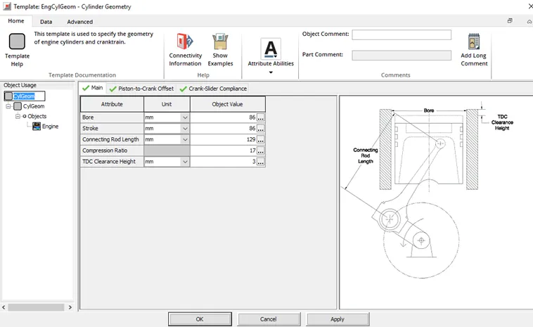
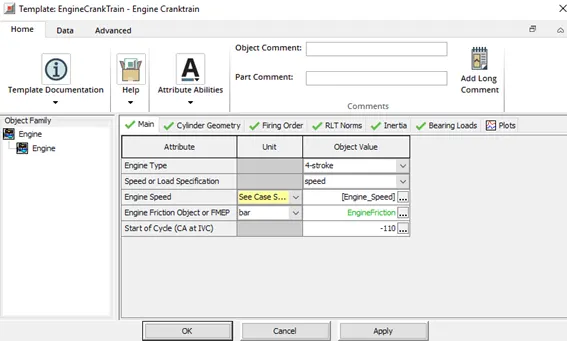
Compressor setup
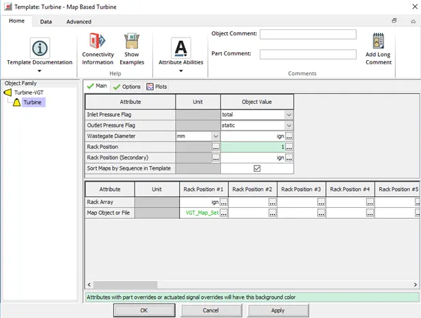
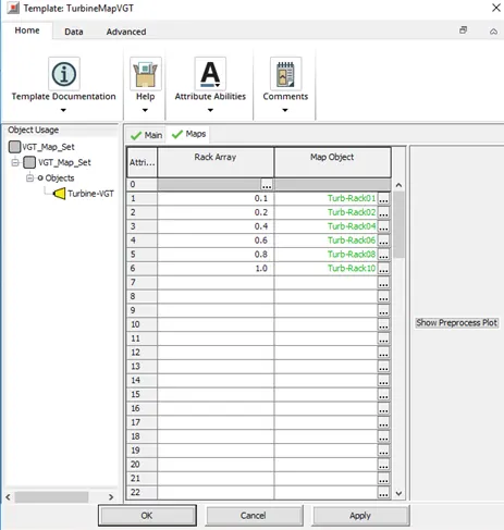
Turbine setup
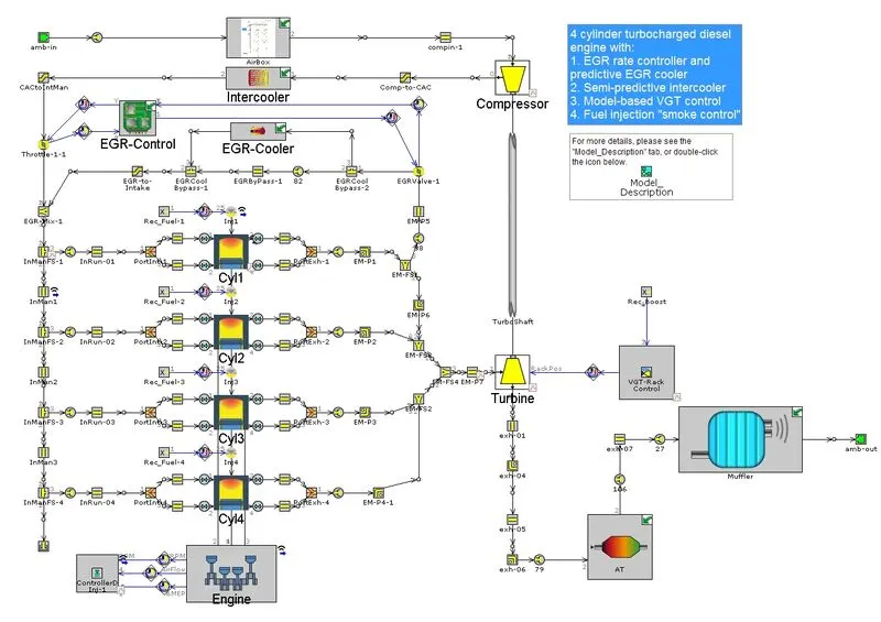
In this model, we can see that the exhaust exit is divided into 3 parts. One part of the exhaust gas goes through the EGR system, one part goes through the after-treatment system and the last part of the exhaust gas goes through the VGT turbocharger system.
The turbine part of the turbocharger is controlled by the VGT rack control module which controls the position of the guide vanes of the turbo housing.
The rec boost template is connected to the vgt rack control. It receives the signals from the ECU wirelessly to tell the VGT rack controller about the boost pressure at a particular RPM. If the boost pressure is going high which needs to be lower the VGT rack controller changes the position of the guide vanes that permits only the required amount of exhaust gases so that the mechanical failure of the turbo can be prevented.
This technology helps to reduce the turbo lag and allows the engine to perform better at every operating range.
Summary:
- Turbochargers/ Superchargers are used to provide more air to the cylinder for better combustion.
- Turbochargers take energy from the exhaust kinetic energy of the engine whereas superchargers take energy from the engine directly.
- Turbochargers face turbo-lag due to the lower RPM of the engine. Hence turbochargers are often not comfortable for passenger vehicles in cities. Superchargers do not face any such issues.
- To control the amount of kinetic energy entering the turbocharger, many configurations such as Waste gate controller, Variable geometry turbine, etc are used.
- The compressor map or turbine map data is of vital importance and the operating range has to be carefully chosen according to the requirement of power and torque. The data for the same is given by the supplier.
- Usually, turbochargers are used in Diesel engines.
Conclusion:
Modeling of different types and configurations of Turbocharger was done. Modeling of the supercharger was also studied.