Week 4-1D Element Creation Challenge
Element Creation Challenge-
AIM-
To mesh the Given component with the Size of 5 Units and create 1D elements on the following component with given cross-section and DOF.
OBJECTIVE-
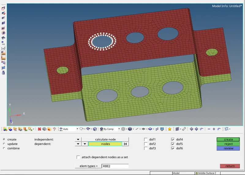
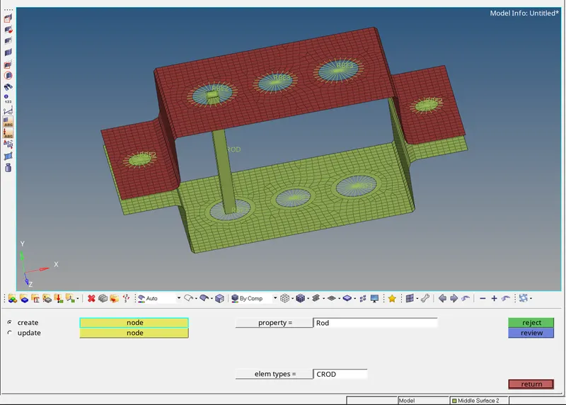
a. Rod element:- Translational DOF should be Constrained with RBE2 link
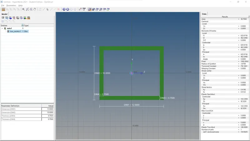
Cross-Section: BOX- Dimension a= 12 mm
dimension b=10 mm
Thickness t= 0.75 mm
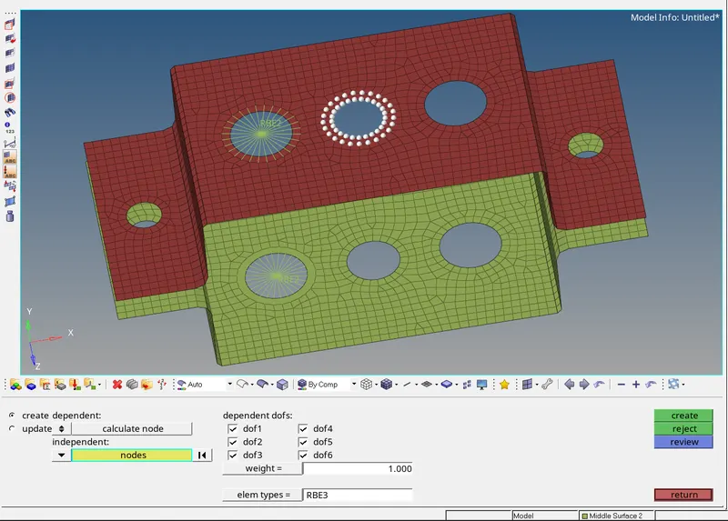
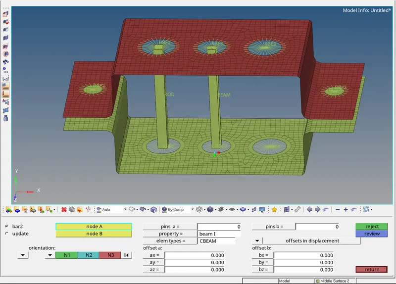
b. Beam element:- All DOF should be constrained with RBE3 link
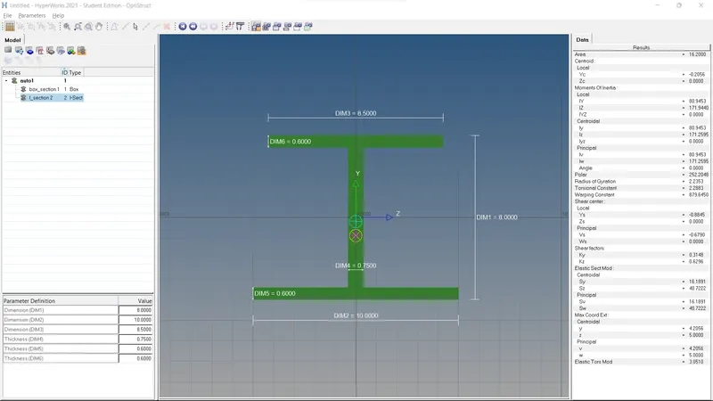
Cross-Section: I Section- Dimension a= 8 mm
Dimension b= 10 mm
Dimension c= 8.5 mm
Thickness t1= 0.75 mm
Thickness t2= .6 mm
Thickness t3= .6 mm
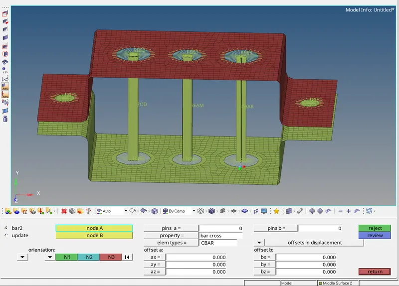
c. Bar element:- Constrain only x and y DOFs With RBE3 link
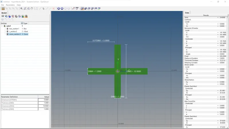
Cross-section: cross(X) section- Dimension DIM1= 5 mm
Thickness DIM2= 1.2 mm
Dimension DIM3= 10 mm
Thickness DIM4= 1.2mm
d & e. Apply the mass of magnitude 10 with the RBE2 link
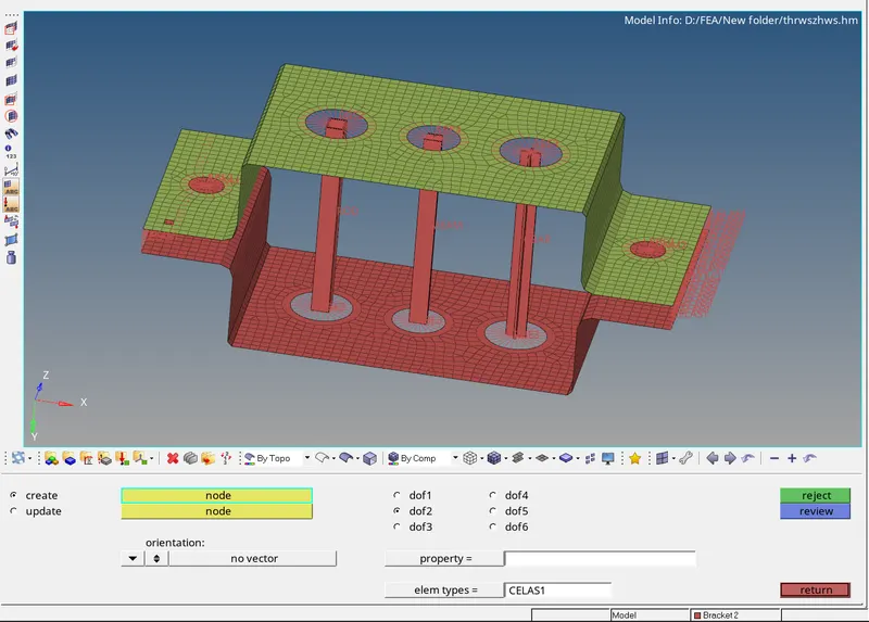
f. Join the two components with Spring elements
PROCEDURE-
- Import the model. Go to File >> Import-Geometry >> (Select file) >> Import
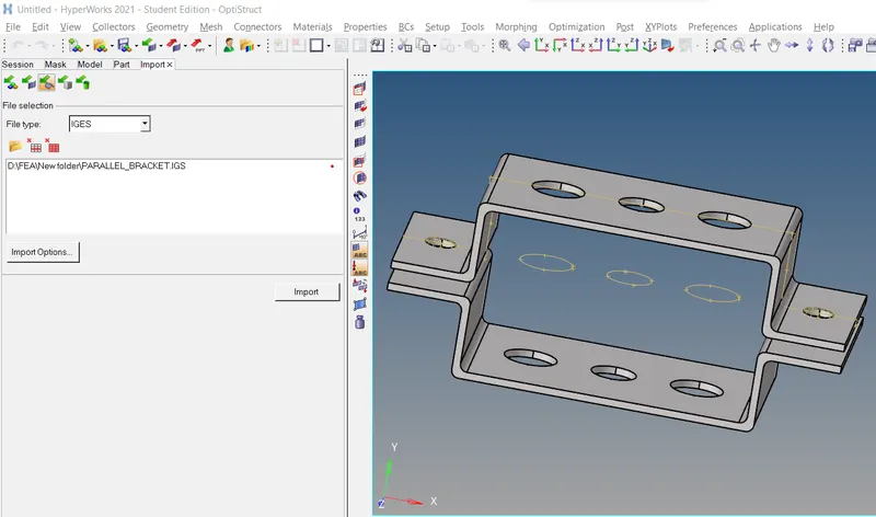
- Mid-Surface Generation
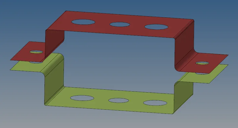
Mid Surface is just created because the 3D model has uniform thickness all over the part. So to make the analysis faster the part is converted to a 2D meshed part.
Click on Geometry>midsurface>auto midsurface(choose skin offset in extraction options)
Now that the mid-surface is created, we can delete the solid surfaces using Delete option by Tool>Delete>solid>select solids>delete entity.
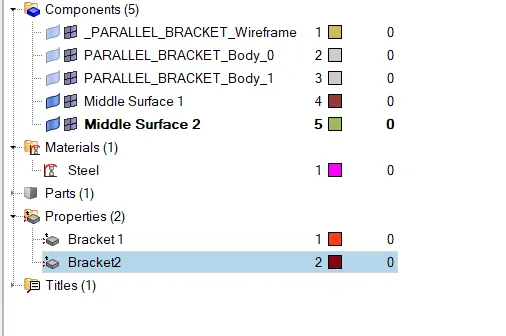
- Creating Material(Steel)
- Creating Property
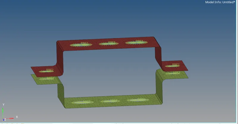
The Parallel Brackets have two Parts parallelly facing each other.
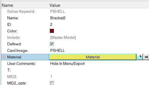
Now creating two properties naming Bracket1 and Bracket2.
After creating the properties give the material(Steel) in its options.
- Creating Washer Splits.
The washer splits are created on the holes of the mid surface of 5mm by Geometry>quick edit>washer split>select the holes and specify the offset value.
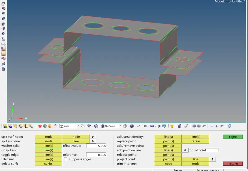
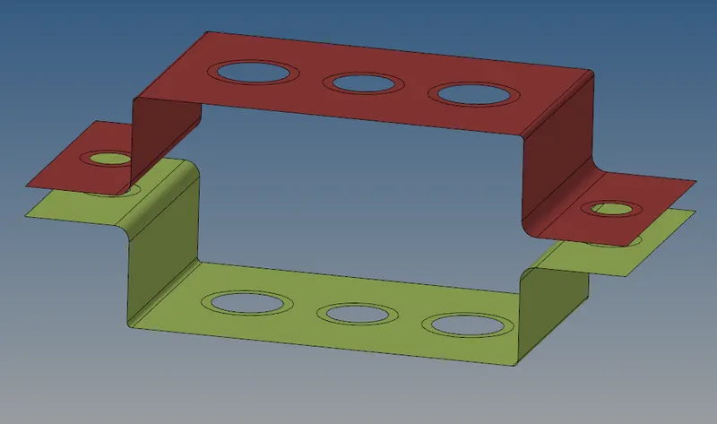
- Creating the 2D mesh on the mid surfaces
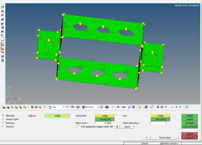
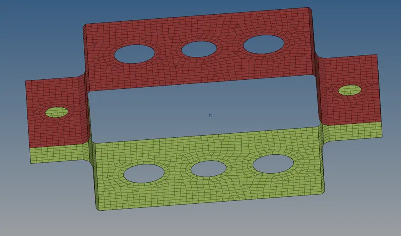
- Now create the RBE2, RBE3, spring, mass links for the brackets.
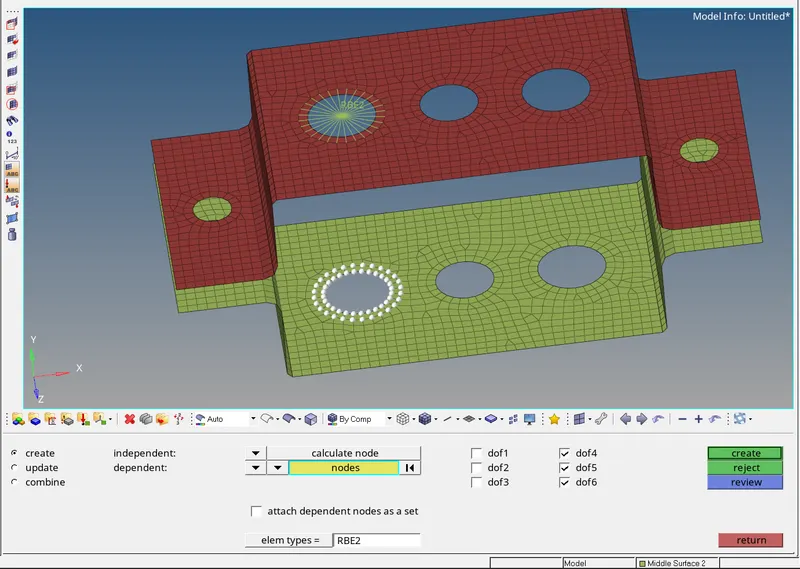
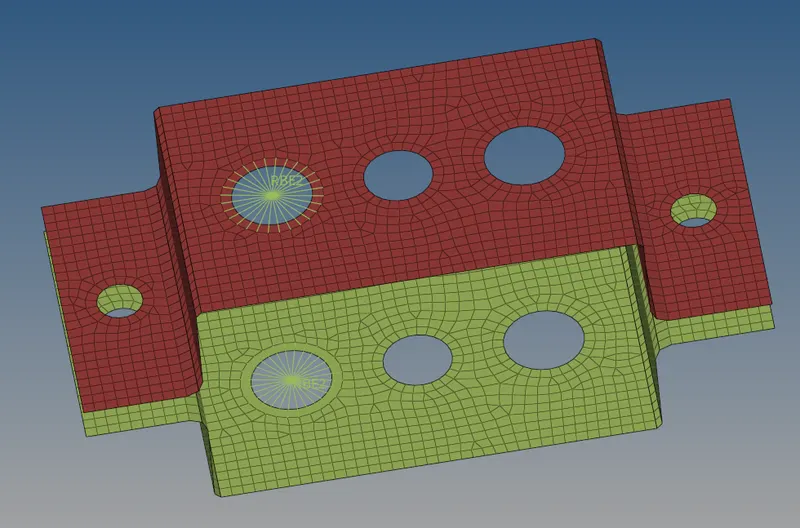
RBE2- A
Select the nodes by selecting the following options
The same options apply for the bottom bracket too
RBE3- B
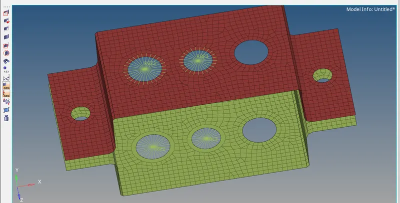
RBE3- C
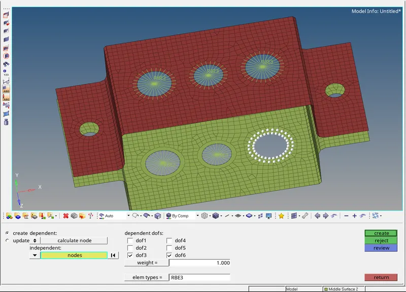
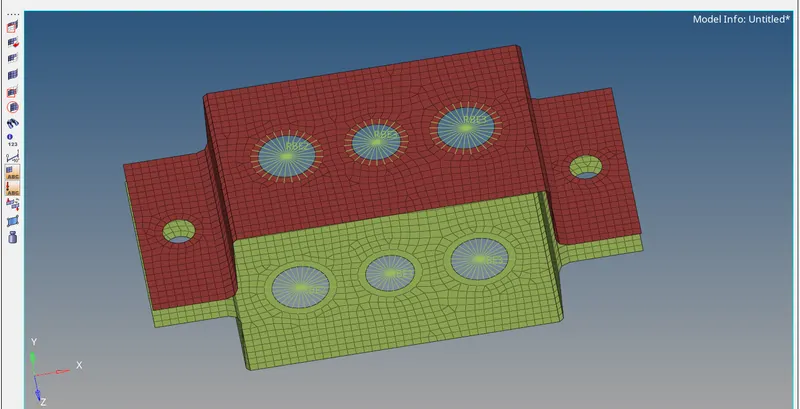
RBE2- D&E
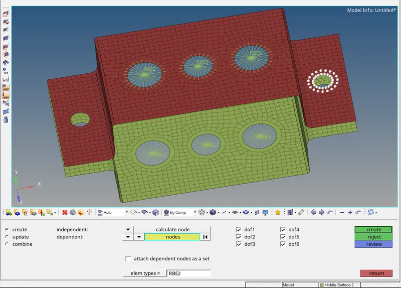
create the same elements for all the remaining holes too
- Creating the Cross sections
- Crearing the properties for the bar elements and assigning the
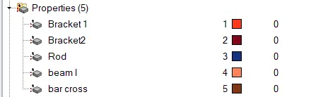
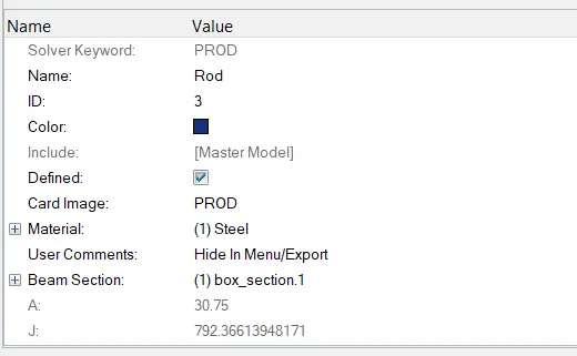
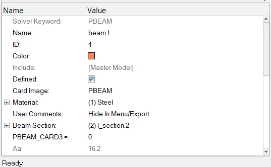
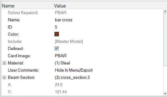
- Creating the BAR, BEAM, ROD elements for the RBE2 and RBE3 links
ROD element- A
Beam Element- B
BAR ELEMENT- C
MASS of magnitude 10- D&E
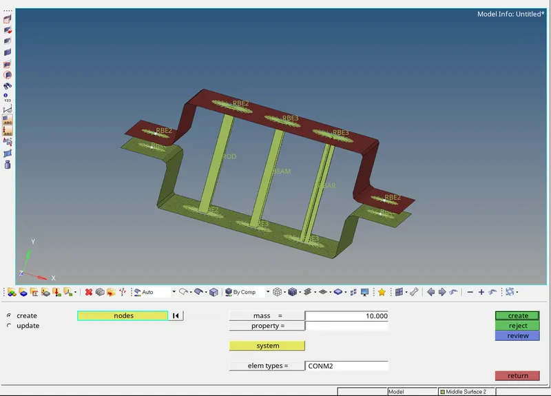
- Creating spring elements for the nodes on the free edges.
RESULT-
Hence all the required objectives are fulfilled:
a - Rod element Created with only translational DOF and RBE2 link.
b - Beam Element Created with all DOF and RBE3 link.
c - Bar Element Created with only x & Y DOF and RBE3 link.
d & e - Mass added on the Master node of RBE2 link.
f - Two Components were joined with Spring Elements.