Week 11 - Final project
FINAL PROJECT
DEVELOPMENT OF DOOR PANEL
AIM-
To create the cad model(Involves creating Class-B surface and Class-C surface and the solid part from the Class-A, B, C surfaces and the attachment features on the b-Surface like Dog Houses, Heat stakes, Push Pins) from the given Class-A surface and Master-Sections by using the attachment strategies and also considering the nominal thickness and also providing the draft analysis for all the parts created.
INTRODUCTION-
Engineering features are the extensions on the plastic components such as ribs, Screw bosses, heat stakes, locators etc., which help fix the plastic component to the main surface and to avoid plastic defects while manufacturing the component through mould process.
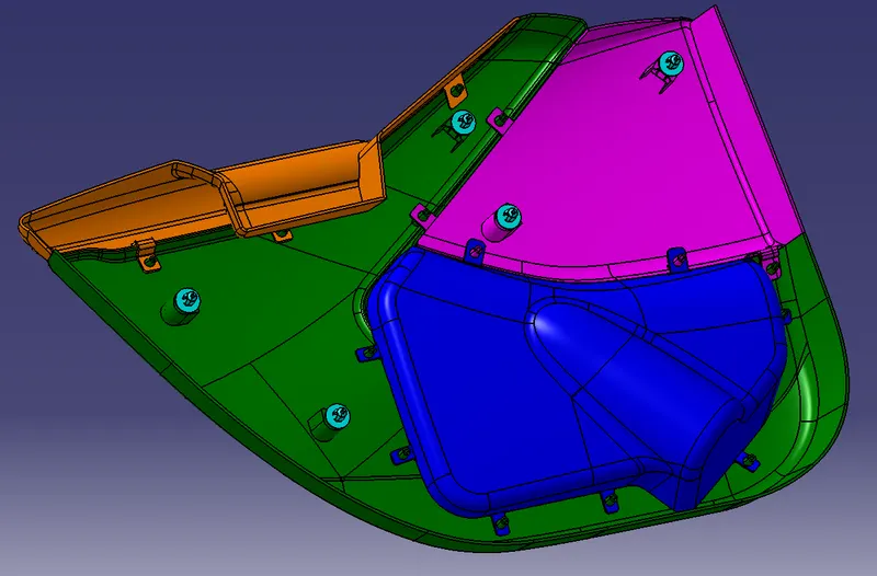
The features such as Dog Houses, Push Pins and Heat stakes are to be added for the component, shown below.
PROCEDURE-
- The creation of the Door Trim Panel(only parts like Lower Substrate, Map Pocket, Arm Rest) involves creating B-Surface, C-Surface and solid part from them and provide with engineering Features like Dog Houses, Push Pins, Heat Stakes.
- Identify the Appropriate Class-A Surfaces for the Lower substrate, Armrest and Map Pocket.
- Develop the flanges for Heat Stakes.
- Create the Tooling Axis For each component and check the Draft Analysis for each of them whether they can be drafted in that particular direction, edit if required.
- Create The Parting Line and Parting Surface for all the parts and check for tooling feasibility.
MAP POCKET-
- Identify the Class-A Surface from the given Trims and create an appropriate Geometrical Set for the Class-A surfaces.
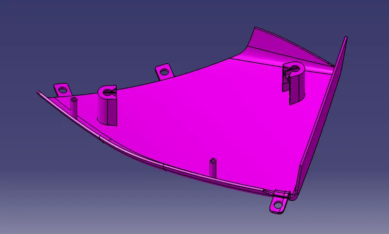
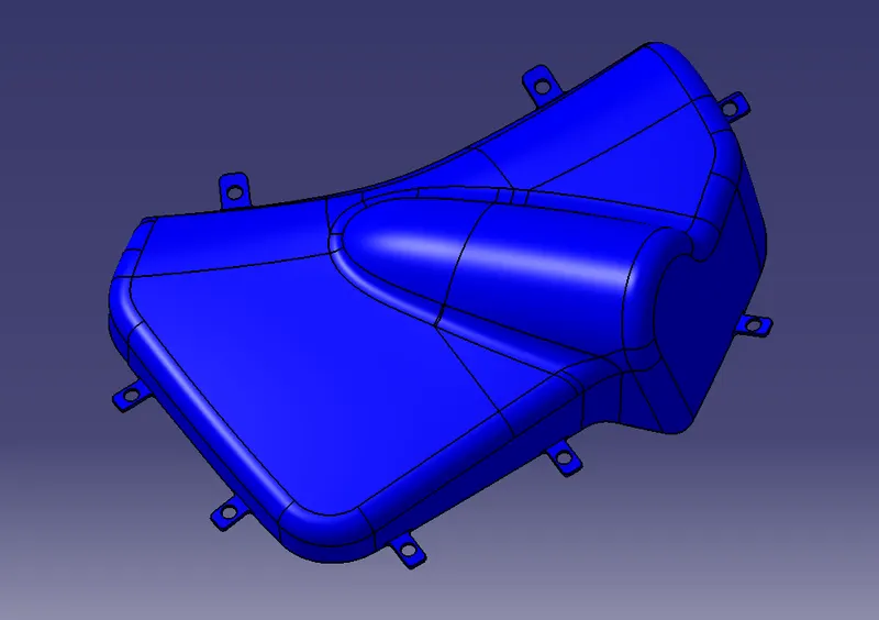
- The Map Pocket consisting of two Parts(From the Given Class-A) named Upper And Lower.
Introduction-
An automotive interior trim assembly having a map pocket. The trim assembly comprises a trim panel and a housing that forms at least a portion of the map pocket. The housing is coupled to the trim panel to define a cavity having an opening for accessing the cavity.
Construction Procedure-
Upper Part-
- Create a join for the Upper part class-A surface.
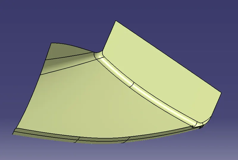
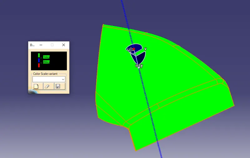
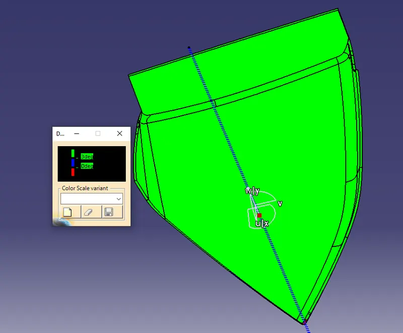
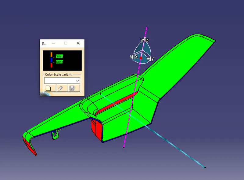
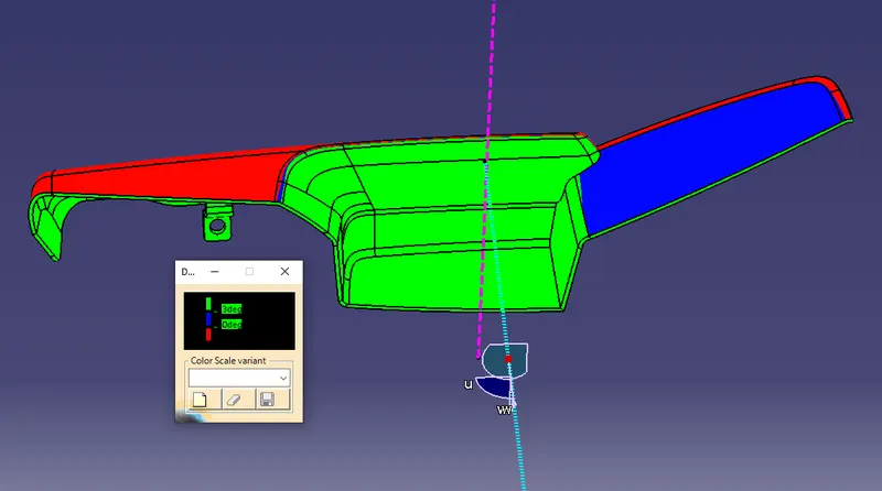
- Create the tooling axis at a point on the surface in Y-Direction and check the Draft Analysis for the class-A whether it can be tooled in that particular direction, edit if required.
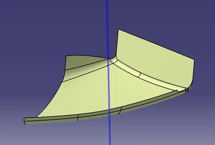
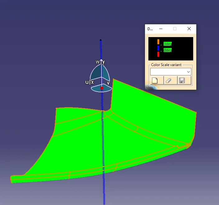
- Create the Class-C surface for the upper part by creating a boundary on the upper part .
- By using the Swept option create the class-C surface using the reference Surface(The Class-A surface itself) for the desired length and the angle to be provided is 90 degrees.
- The class surface is now created and the class- a and class-c surfaces are now joined so that it can trimmed with the class-b Surface to create the solid Part.
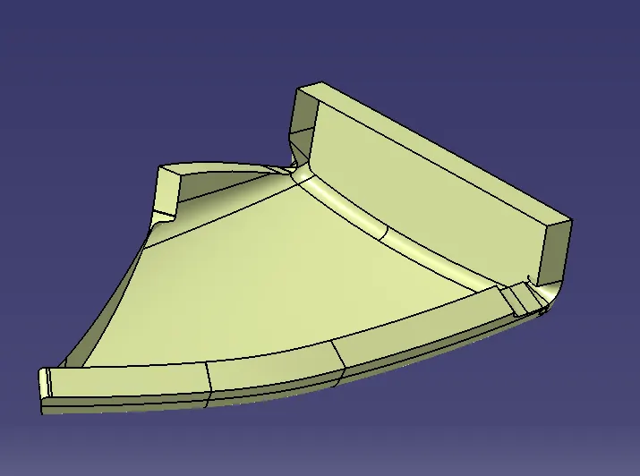
- Creating the Class-B surface- To create the class-b surface you need to know the nominal thickness(Refer the master-section for thickness). Offset the whole A-Surface for 2.5mm.
- The acquired surface will not be suitable for trimming it with Join created with A, C-surfaces as the C-Surface is provided with draft and so the error would be Connexity error. So, to avoid this kind of errors we just need to extrapolate the whole class-B surface by some distance in curvature propagation.
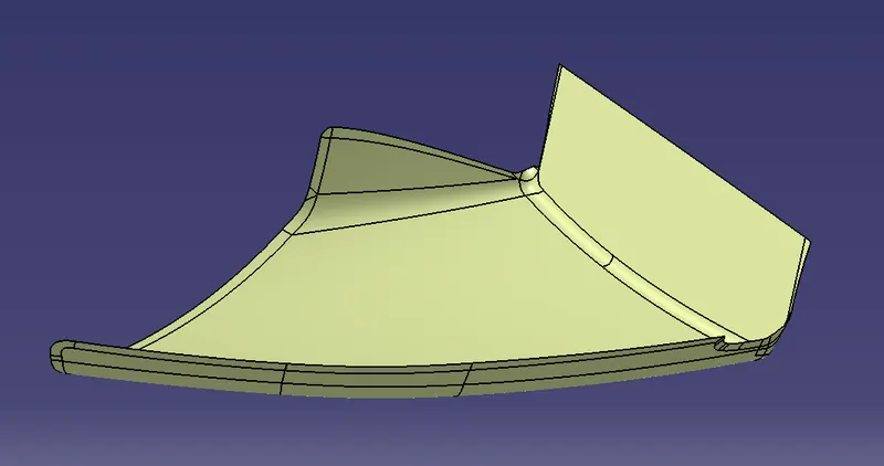
- From the acquired B-Surface and the Join created with Class-A,C surface Trim these Two to get the closed part.
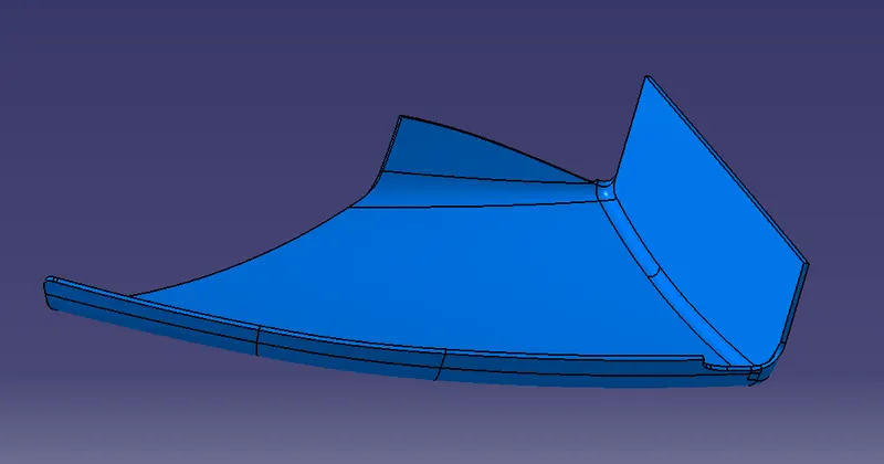
- Now just go from GENERATIVE SHAPE DESIGN TO MECHANICAL DESIGN>PART DESIGN to create the Thick-surfacein a Part Body and name it MAP POCKET UPPER Part for reference.
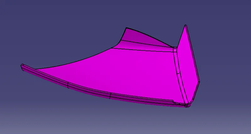
- To Create the Flanges for the Upper part extract one of the surfaces(C-surface for this instance). The Flanges are also to be provided with to be provided with 3 degree draft along the tooling direction. The flange thickness is 2.5mm and its width is 16mm and the length depends upon the surface it is getting fitted with(The Map Pocket is to be fitted with the Lower Substrate). The Flanges are provided with 9mm dia holes which are to be drafted along the tooling direction of the Lower Substrate Direction since the heat stakes are attachedto the lower substrate itself.
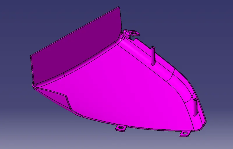
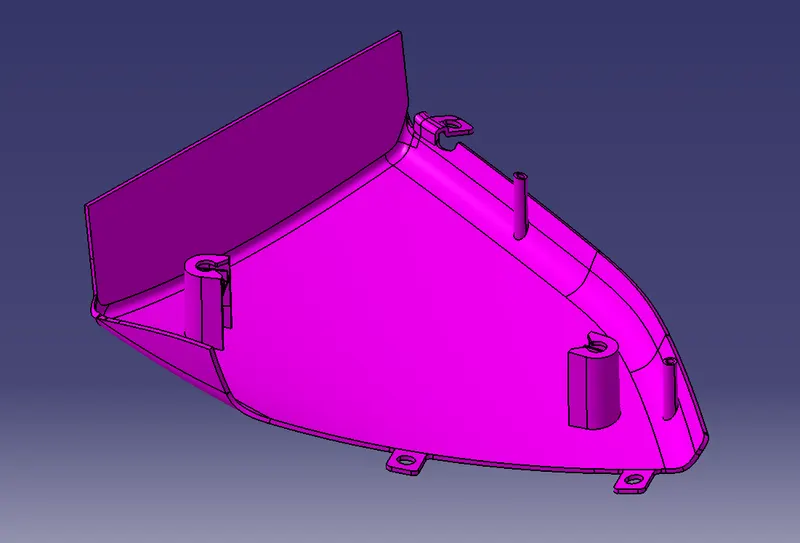
- The Map Pocket Upper part comprises of Flanges and Dog Houses and Push Pins placed over the Dog Houses For Attachment.
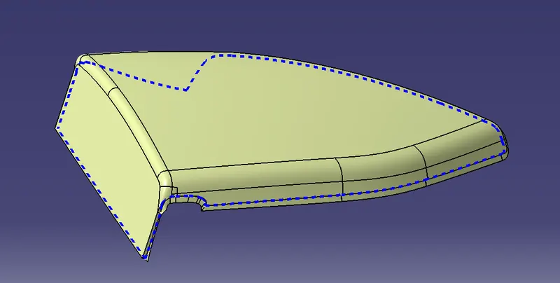
Parting Line-
A parting line the line on the part where cavity and core meet. The line lies on the parting surface which is a plane where the core and cavity touch each other when they are in closed condition.
Draft Analysis-
Lower Part-
- Create a join for the LOWER part class-A surface.
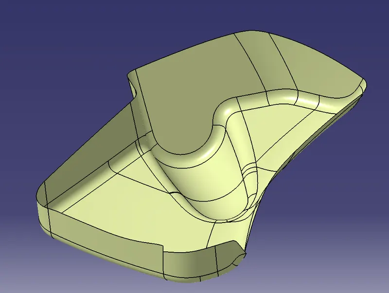
- Create the tooling axis at a point on the surface in Y-Direction and check the Draft Analysis for the class-A whether it can be tooled in that particular direction, edit if required.
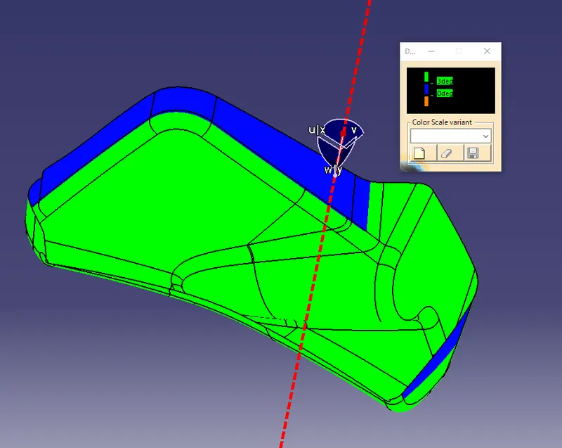
- Create the Class-C surface for the upper part by creating a boundary on the lower part.
- By using the Swept option create the class-C surface with the referenceSurface(The Class-A surface itself) for the desired length and the angle to be provided is 90 degrees.
- The class surface is now created and the class- a and class-c surfaces are now joined so that it can trimmed with the class-b Surface to create the solid Part.
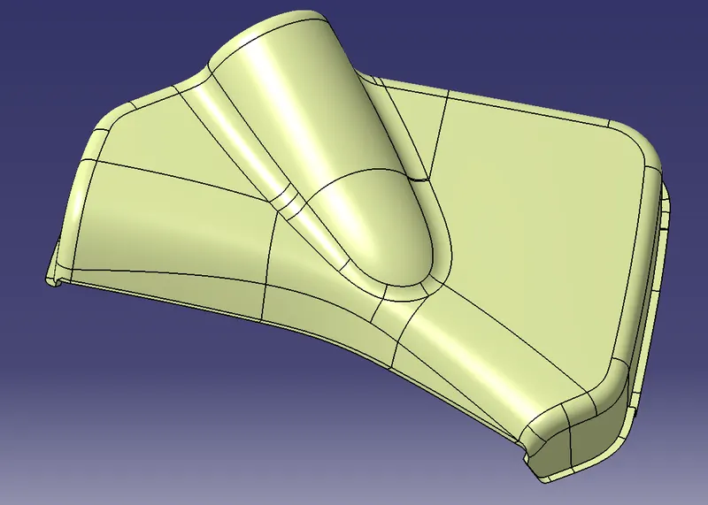
- Creating the Class-B surface- To create the class-b surface you need to know the nominal thickness(Refer the master-sectionfor thickness). Offset the whole A-Surface for 2.5mm.
- The acquiredsurface will not be suitable for trimming it with Join created with A, C-surfaces as the C-Surface is provided with draft and so the error would be Connexity error. So, to avoid this kind of errors we just need to extrapolate the whole class-B surface by some distance in curvature propagation.
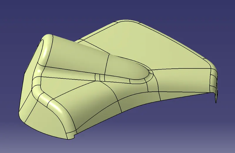
- From the acquiredB-Surface and the Join created with Class-A,C surface Trim these Two to get the closed part.
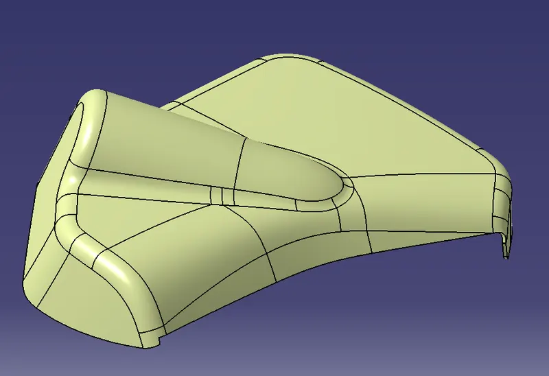
- Now just go from GENERATIVE SHAPE DESIGN TO MECHANICAL DESIGN>PART DESIGN to create the Thick surfacein a Part Body and name it MAP POCKET LOWER Part for reference.
- To Create the Flanges for the Lower part extract one of the surfaces(A-surface for this instance). The Flanges are also to be provided with to be provided with 3 degree draft along the tooling direction.The lower Part fits with two other parts namely Lower Substrate and Upper Part of Map pocket. The flange thickness is 2.5mm and its width is 16mm and the length depends upon the surface it is getting fitted with(The Map Pocket lower part is to be fitted with the Lower Substrate and the Map Pocket Upper part also).The flanges which are to be fitted by heat stakes of lower substrate has the holes of 9mm dia drafted with the tooling direction of lower substrate only and the flangeswhich are to be fitted by heat stakes of the map pocket upper part has the holes of 9mm dia drafted with the tooling direction of the Upper Part only.
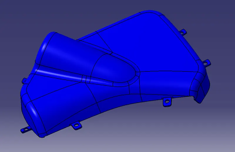
- The Map Pocket Lower part comprises of Flanges only.
Parting Line-
A parting line the line on the part where cavity and core meet. The line lies on the parting surface which is a plane where the core and cavity touch each other when they are in closed condition.
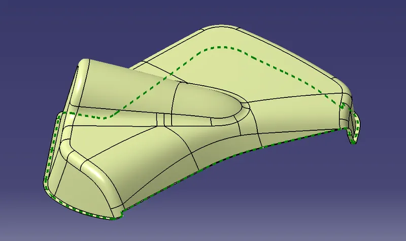
Draft Analysis-
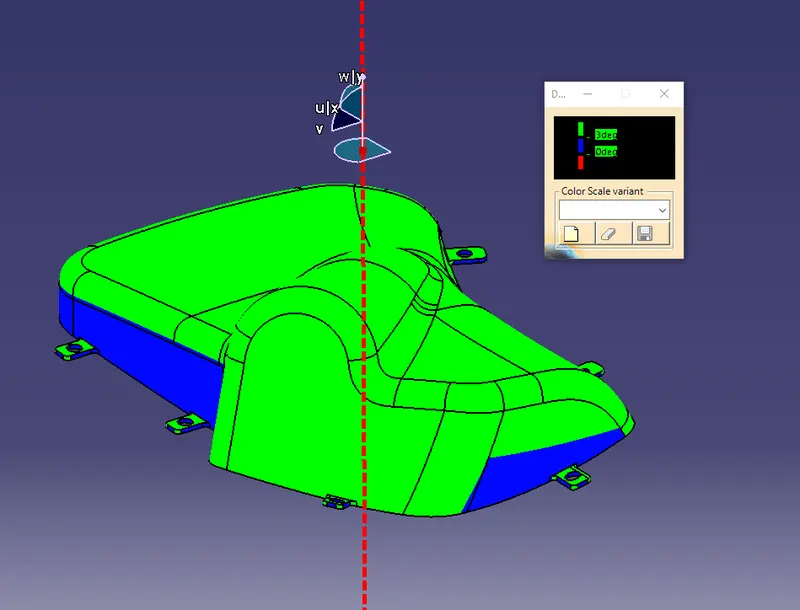
LOWER SUBSTRATE-
Introduction-
The lower Substrate is a Trim found in the door panel whose environment is Map Pocket, Door armrest and Upper Substrate.
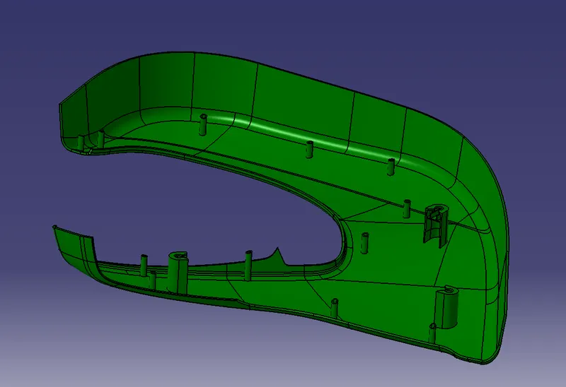
Construction Procedure-
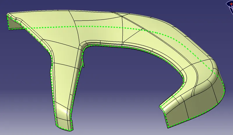
- Identify the Class-A surface and Create a join for the Lower Substrate class-A surface.
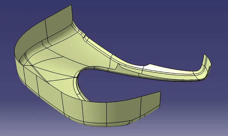
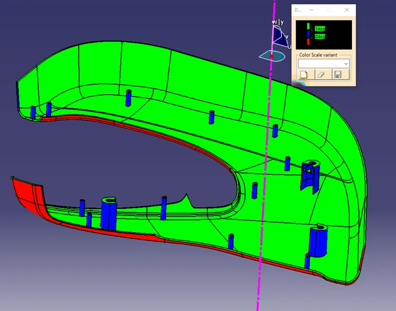
- Create the tooling axis at a point on the surface in Y-Direction and check the Draft Analysis for the class-A whether it can be tooled in that particular direction, edit if required.
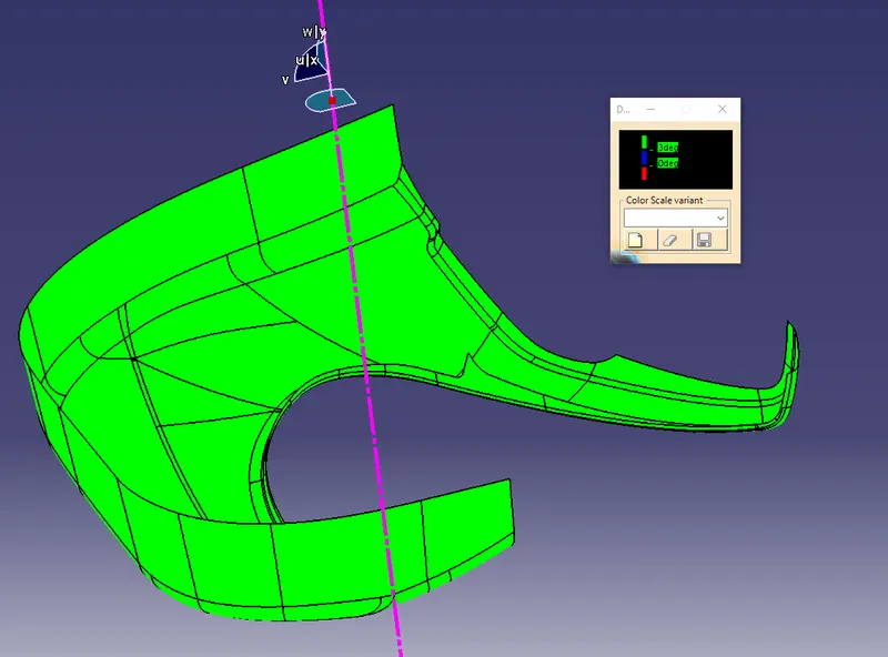
- Create the Class-C surface for the Lower Substrate part by creating a boundary on the upper part.
- By using the Swept option create the class-C surface with the referenceSurface(The Class-A surface itself) for the desired length and the angle to be provided is 90 degrees.
- The class surface is now created and the class- a and class-c surfaces are now joined so that it can trimmed with the class-b Surface to create the solid Part.
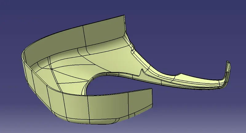
- Creating the Class-B surface- To create the class-b surface you need to know the nominal thickness(Refer the master sectionfor thickness). Offset the whole A-Surface for 2.5mm.
- The acquiredsurface will not be suitable for trimming it with Join created with A, C-surfaces as the C-Surface is provided with draft and so the error would be Connexity error. So, to avoid this kind of errors we just need to extrapolate the whole class-B surface by some distance in curvature propagation.
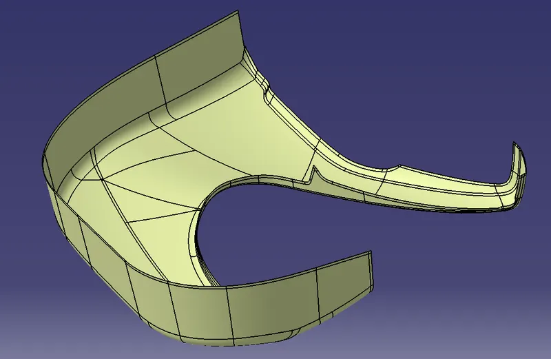
- From the acquiredB-Surface and the Join created with Class-A,C surface Trim these Two to get the closed part.
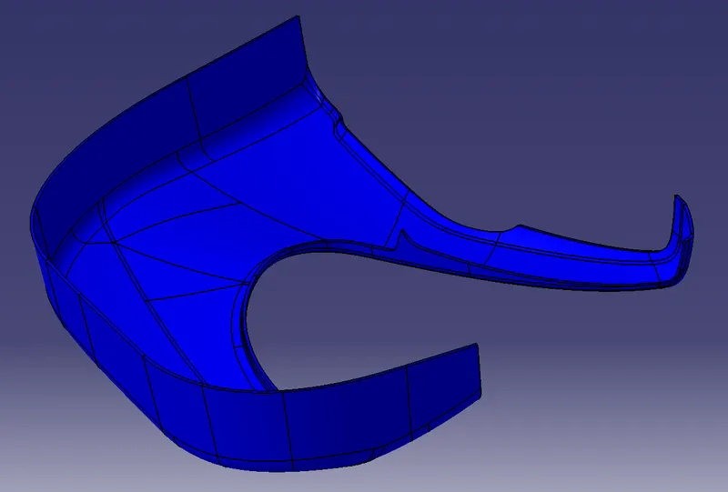
- Now just go from GENERATIVE SHAPE DESIGN TO MECHANICAL DESIGN>PART DESIGN to create the Thick-surfacein a Part Body and name it LOWER SUBSTRATE Part for reference.
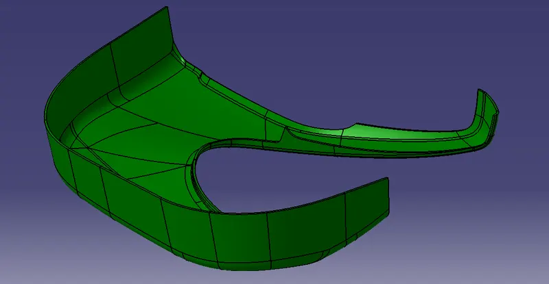
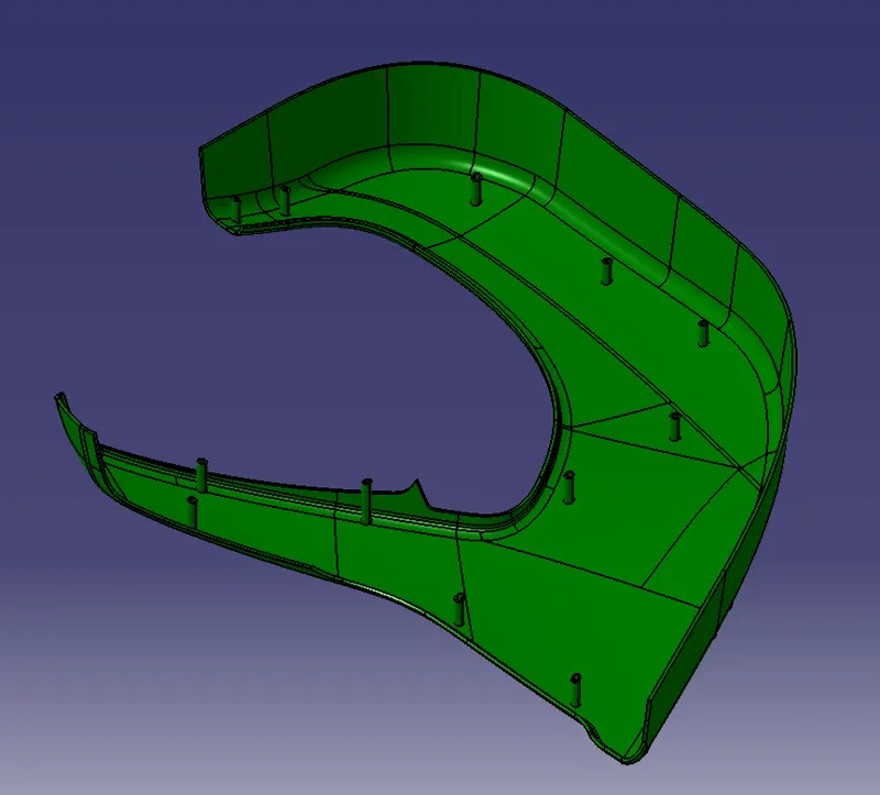
- The Lower Substrate part comprises of Heat Stakes and Dog Houses with Push Pins only. Its construction is detailed below.
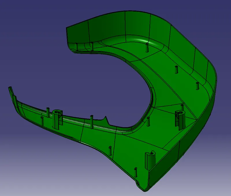
Parting Line-
A parting line the line on the part where cavity and core meet. The line lies on the parting surface which is a plane where the core and cavity touch each other when they are in closed condition.
Draft Analysis-
ARMREST-
Introduction-
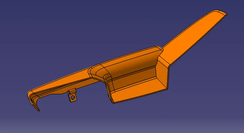
In an automotive context, an armrest (or arm rest) is a feature found in many modern vehicles on which occupants can rest their arms. Armrests are typically made from durable materials. Hard plastic, polyurethane, are the most common.
Construction Procedure-
- Identify the Class-A surface and Create a join for the Lower Substrate class-A surface.
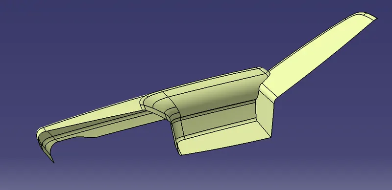
- Create the tooling axis at a point on the surface in Y-Direction and check the Draft Analysis for the class-A whether it can be tooled in that particular direction, edit if required. Since there is pocket for the armrest and it could not be tooled in the main tooling axis this part also requires the Slider axis for the Pocket part.
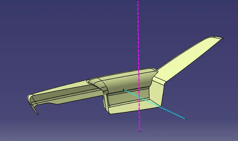
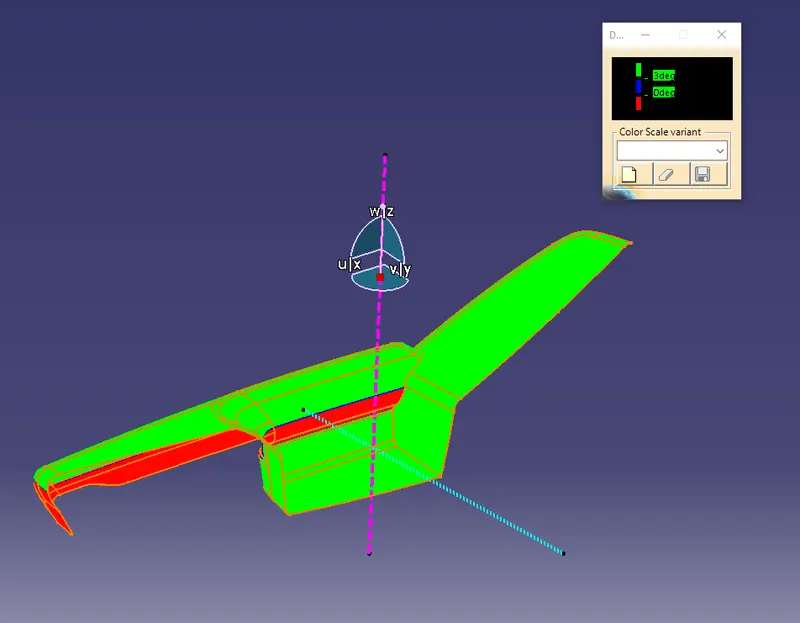
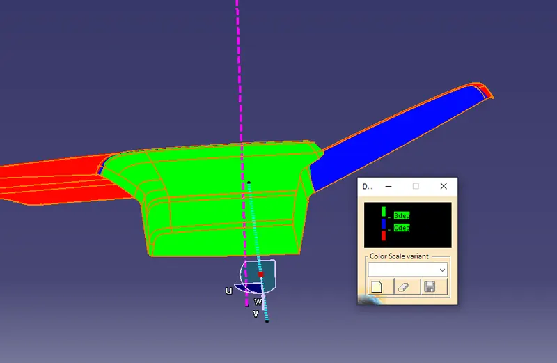
- Split the Armrest for convenience and develop the surfaces.
- Create the Class-C surface for the Armrest part by creating a boundary.
- By using the Swept option create the class-C surface with the referenceSurface(The Class-A surface itself) for the desired length and the angle to be provided is 90 degrees for some extent where there is a flanged part. The Area where there is noo flanged part there the c-surface should be along the Tooling direction and the draft angle 3 degrees should be given.
- The class-c surface is now created and the class- a and class-c surfaces are now joined so that it can trimmed with the class-b Surface to create the solid Part.
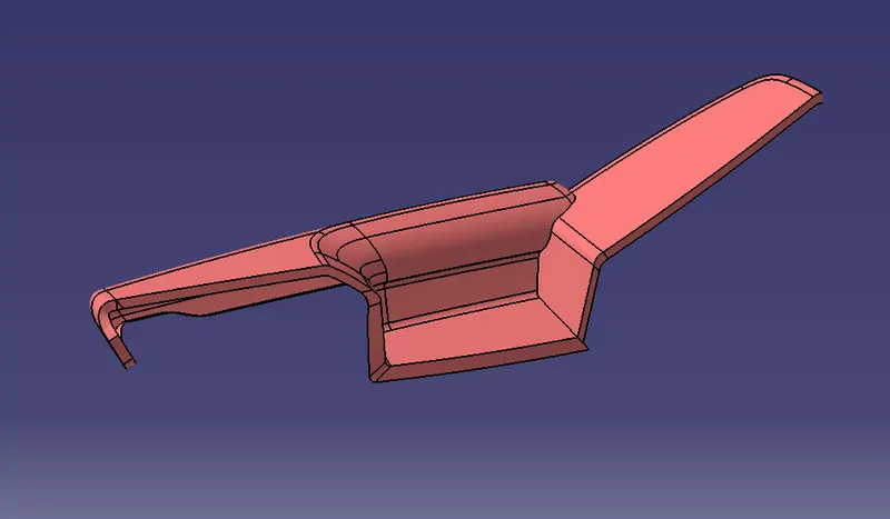
- Creating the Class-B surface- To create the class-b surface you need to know the nominal thickness(Refer the master sectionfor thickness). Offset the whole A-Surface for 2.5mm.
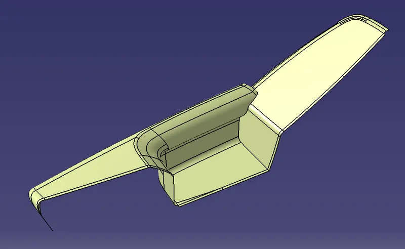
- The acquiredsurface will not be suitable for trimming it with Join created with A, C-surfaces as the C-Surface is provided with draft and so the error would be Connexity error. So, to avoid this kind of errors we just need to extrapolate the whole class-B surface by some distance in curvature propagation.
- From the acquired B-Surface and the Join created with Class-A,C surface Trim these Two to get the closed part.
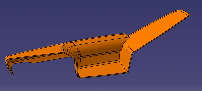
- Now just go from GENERATIVE SHAPE DESIGN TO MECHANICAL DESIGN>PART DESIGN to create the Thick surfacein a Part Body and name it Armrest Part for reference.
- To Create the Flanges for the Armrest extract one of the surfaces(C-surface for this instance). The Flanges are also to be provided with to be provided with 3 degree draft along the tooling direction. The flange thickness is 2.5mm and its width is 16mm and the length depends upon the surface it is getting fitted with(The Armrestis to be fitted with the Lower Substrate). The Flanges are provided with 9mm dia holes which are to be drafted along the tooling direction of the Lower Substrate Direction since the heat stakes are attached to the lower substrate itself.
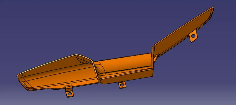
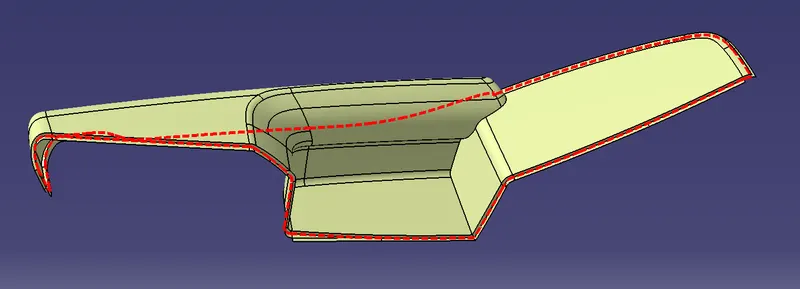
Parting Line-
A parting line the line on the part where cavity and core meet. The line lies on the parting surface which is a plane where the core and cavity touch each other when they are in closed condition.
Draft Analysis-
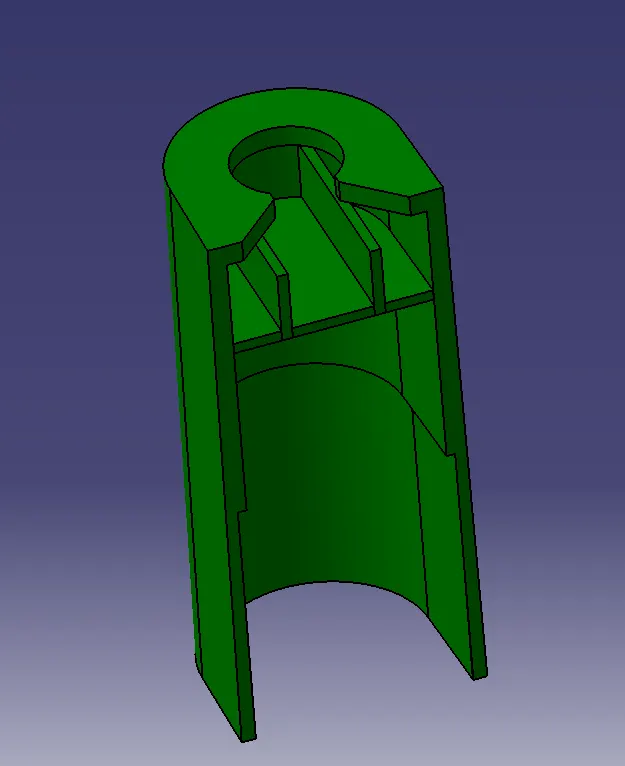
Dog House-
Dog house is an engineering feature used in plastic trim design. ... Sometimes other engineering features like snaps; locators etc. are mounded on them to increase their strength. Dog houses are subjected to draft analysis to prevent breakage of the component during ejection from mould cavity.
Construction-
- Draw the Sketch
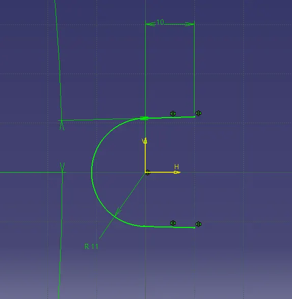
- Extrude it and create a wall and trim it.
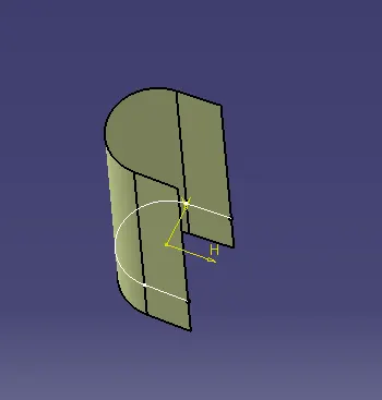
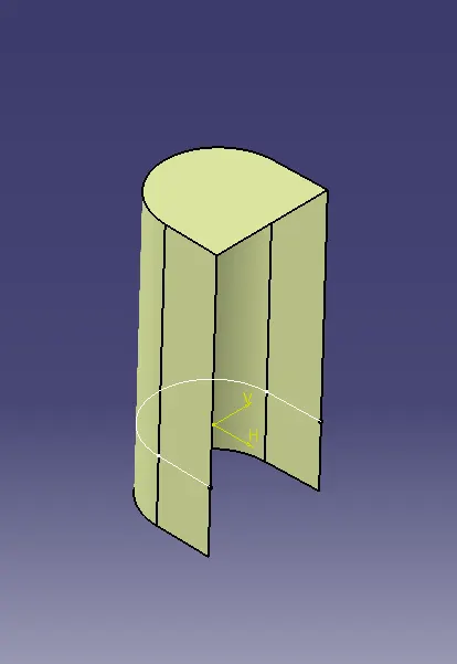
- In part body using the Thick surface create the part body.
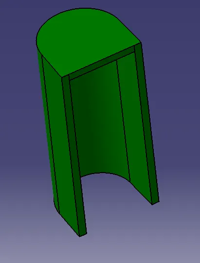
- Split the Dog House to get the appropriate sink Saver.
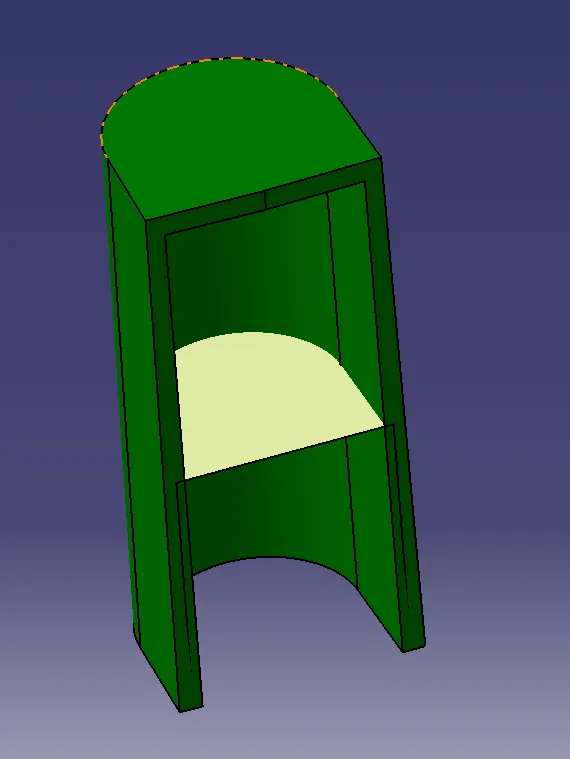
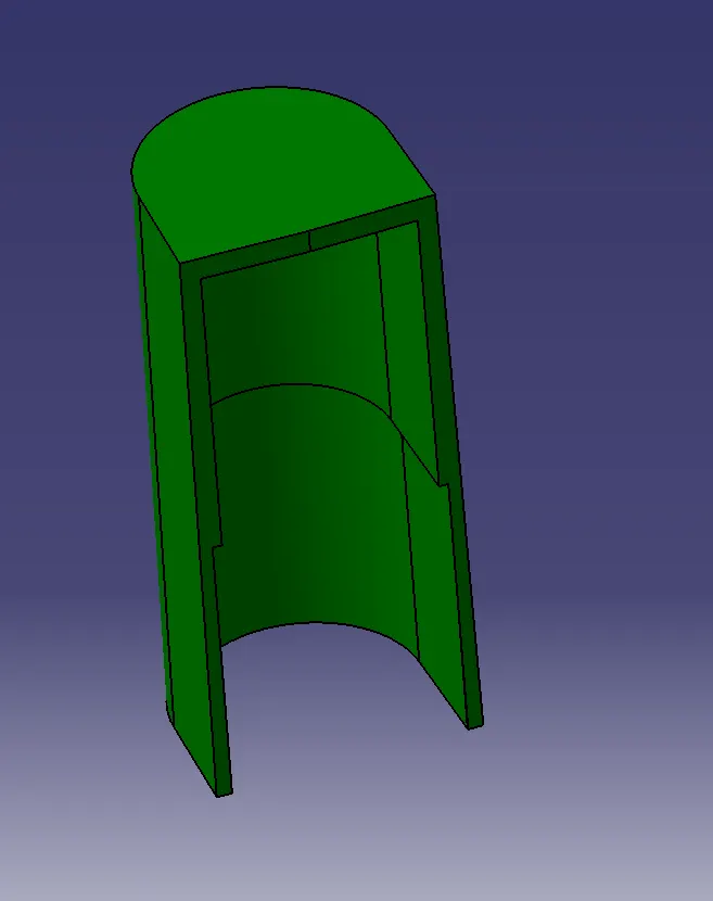
- Split the head of the Dog House so that it can be assembled with Push Pin.
- Create the sketch as required and split it.
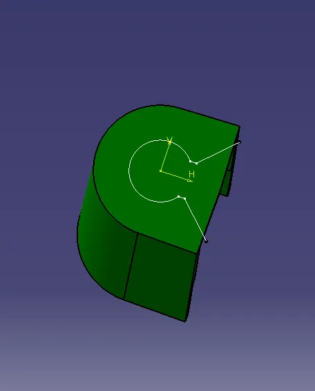
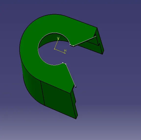
- Create the Dog house Internal walls for Push Pin Support.
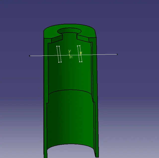
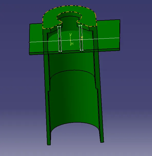
- The Dog House After all the trims and Drafts applied.
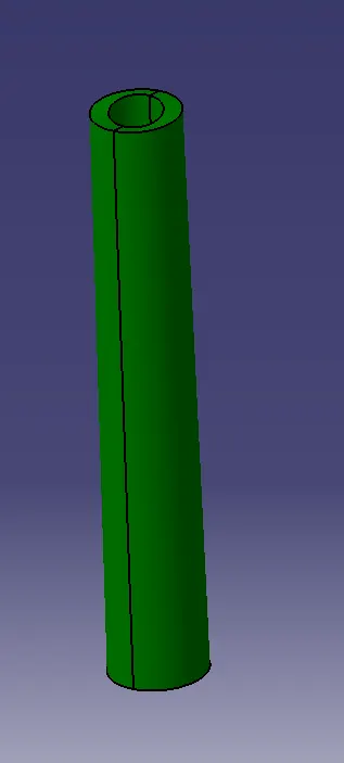
Heat Stakes-
Thermal staking is an assembly method that uses the controlled melting and reforming of a plastic stud or boss to capture or lock another plastic or metal component of an assembly in place.
The diameter adopted for heat stakes is 7.5mm and the height depends upon the fixation with other components.
The heat stakes are made in such a way that the flange hole and heat stake shares the same center. The heat stakes are also to be drafted along the tooling axis of its resepective fitted part. Both the outer and inner parts of the heat stakes are to be drafted along the tooling direction.
For example, if the heat stakes is constucted on a lower substrate ithe tooling direction in which the heat stakes are drafted is the tooling direction of the Lower Substrate.
Push Pins-
- Create the sketch.
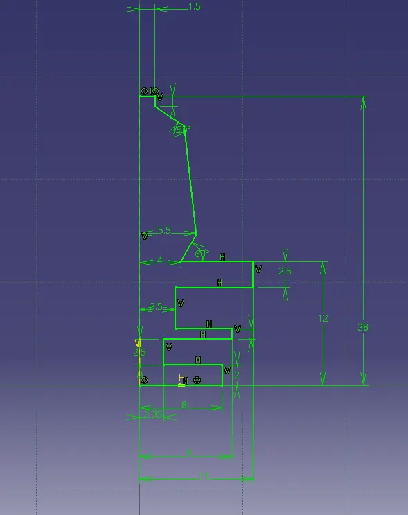
- Shaft the sketch along the vertical axis.
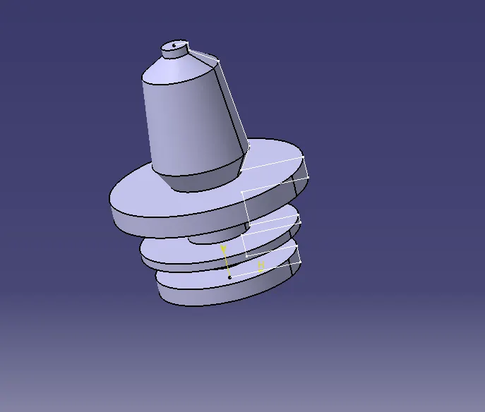
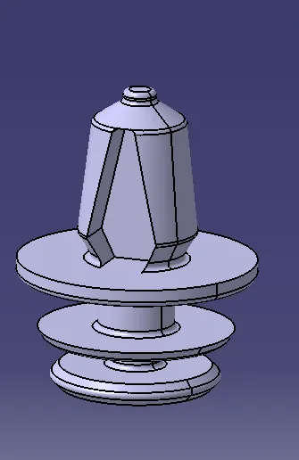
- Create a sketch so that the pocket has been created on the push pin. Make sure the pocket is on the both sides.
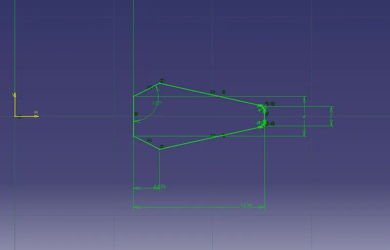
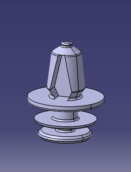
- Give draft as required
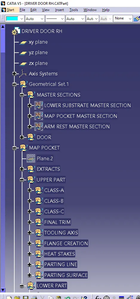
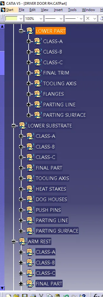
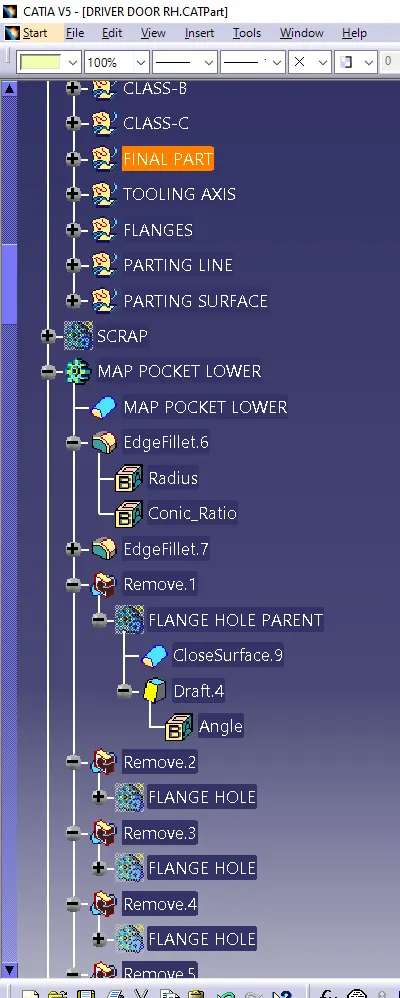
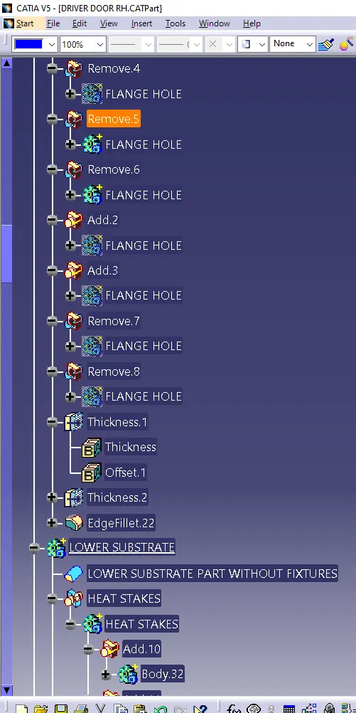
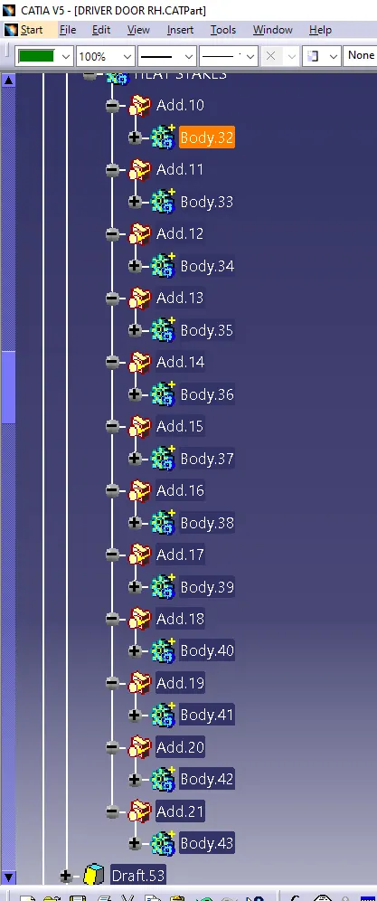
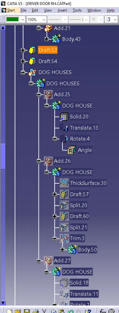
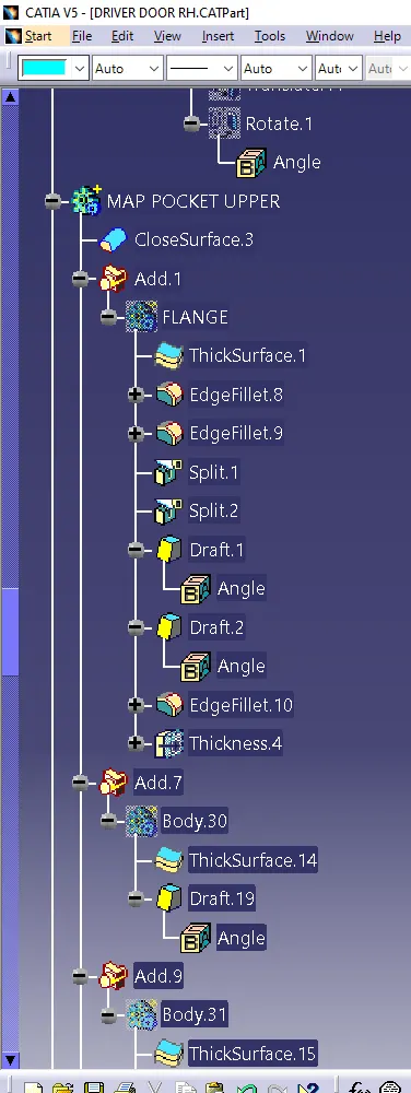
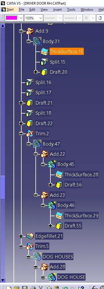
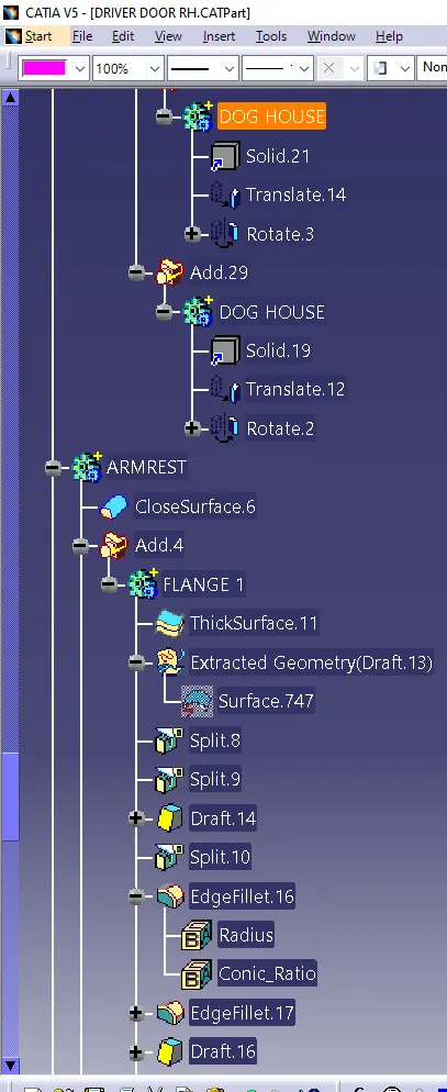
Tree Structure-
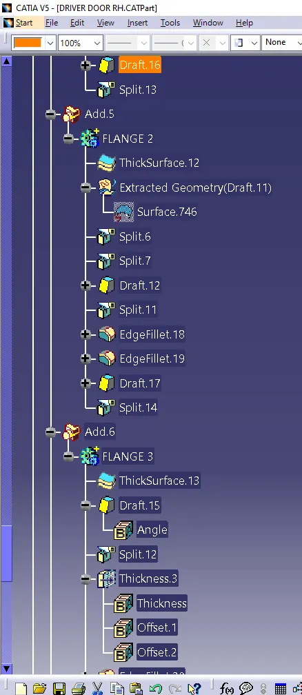
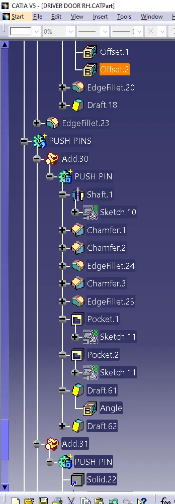
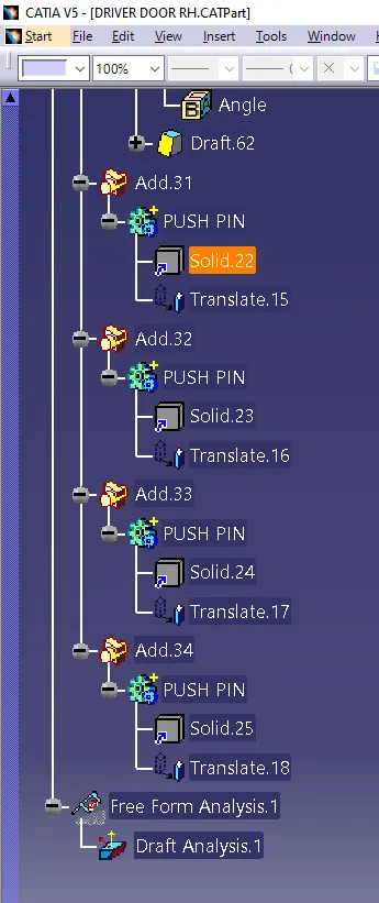
Result-
The Cad model has been created which involves creation of the Class-B and Class-C Surfaces, Closed Bodies, Engineering Features for Fixation Strategy by refering the Master- Sections and Class-A. The optimal thickness used is 2.5mm(Reffered from Master-Sections Provided). The engineering features like Heat Stakes, Dog Houses and Push Pins have been used For fixation Strategy.
The Parts after development looked like