Week -2
1. Model Of DoorBell using Simulink Blocks
For the door bell to ring a plunger has to hit a bell.
The Simulink Blocks used in the simulation are
- Pulse Generator
- Simulink to Physical System Converter
- Switch
- Battery
- Solenoid
- Ideal Translational Motion Sensor
- Mechanical Translational Reference
- Electrical Reference
- Solver Configuration
- Pyysical System to Simulink Converter
- Scope
- Display
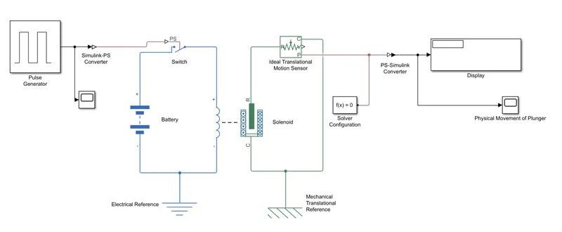
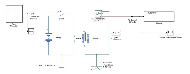
- The Pulse Generator is connected to the switch via a Simulink to PS converter. The Pulse Generator Parameters are changed for requires inputs. As asked The switch needed to be closed for 2 seconds and then released so the period can be given as 4 seconds while the pulse width could be 50%.
- The switch is connected to the battery which is connected to the solenoid.
- The solenoid is connected to the Ideal Rotational Motion Sensor while R of IRMS is connected to the R of Solenoid and C of Solenoid is connected to te C of IRMS with a mechanical Translational Reference.
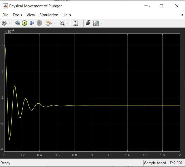
- The PS-Simulnk block is used to display the output from IRMS and a scope is used to watch the movement of the plunger.
2. Thermistor to sense the tempetarure of a heater & turn on or turn off the fan as per below conditions:
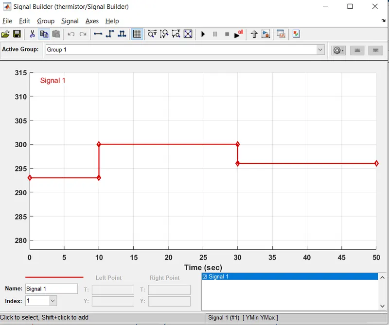
Temperature source: 20 °C from 0 to 10 seconds, 27 °C from 10 to 30 seconds, 23 °C from 30 to 50 seconds
Fan conditions: ON if the temperature above 25 °C, OFF otherwise
For the motor to run the thermistor need to sense the temperature above 25 degrees from the source.
The Simulink Blocks used in the simulation are
- Signal Builder
- Simulink-Ps converter
- Controlled Temperature Source
- Thermal Reference
- Solver
- Thermistor
- Battery
- Electrical reference
- Resistor
- Voltage Sensor
- Ps-Simulink Converter
- Switch
- Controlled Voltage Source
- Dc Motor
- MEchanical Translational Reference
- Ideal Rotational Motion Sensor
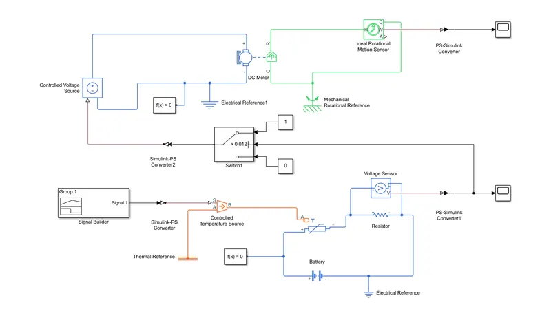
- A signal Builder with pre-defined information of termetatures is connected to the Controlled temperature source which is connected to its reference and the THERMISTOR.
- The A of Thermistor Is connected to the B of CTS which provides the temperature,
- The resistor and Voltage sensor which are already connected parallelly are connected to the thermistor and battery and its refernce
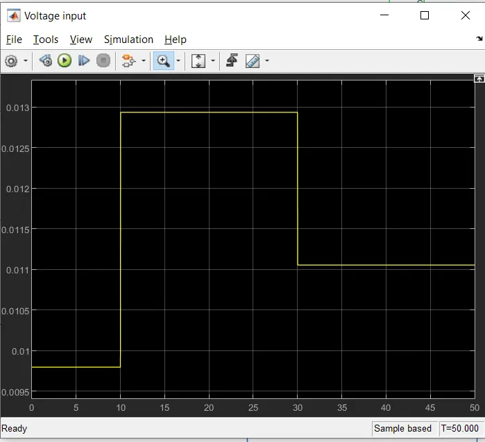
- The switch which is connected to the controlled voltage source which is connected to the DC Motor will receive the Information from the PS-Simulink converter which is connected to the Voltage Sensor.
- The switch is given with certain parameters.
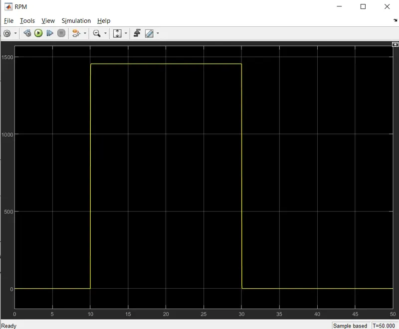
- The motor is connected to the IRMS which checks the rpm of the motor when the voltage is passed to the motor.