Week 3 Challenge : CFD meshing on Turbocharger
SURFACE AND VOLUMETRIC MESHING OF A TURBOCHARGER MODEL IN ANSA
l. OBJECTIVES
1. Clean the given Turbocharger Model geometry.
2. Generate a surface mesh by assigning different mesh sizes to the different parts of the model.
3. Generate a volumetric mesh by creating appropriate control volumes.
ll. PROCEDURE
A. Part 1- Cleaning The model and assigning the PIDs
Step 1-
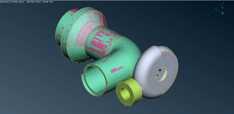
Switch On the Shadow Display mode to display the entire model. Change the Draw Mode from ENT to PID. Switch On the Cons visibility in other modes through the Presentation parameters tab in Quality Criteria.
Step 2 -
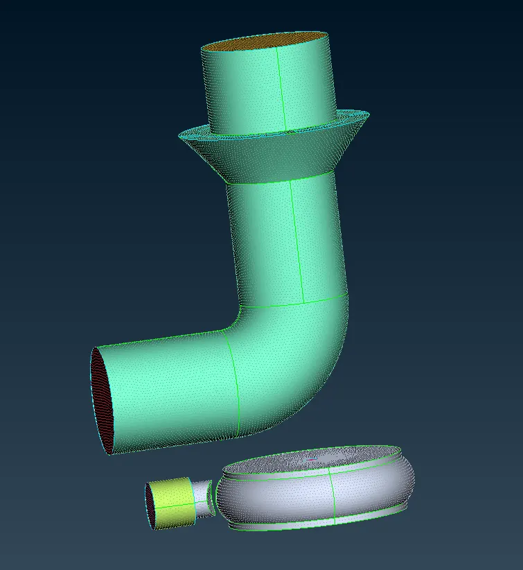
We need to clean the geometry. The given model has several errors that need to be cleared. Some of them include -
1. Several unwanted surfaces, which include those surface which occupy the same space as the required model, and needs to be deleted.
2. Missing surface which is fixed by creating new surfaces in the available gap.
3. Some surfaces cross each other but are not intersecting. To fix we use the "Intersect " tool and then delete the unwanted extruding surfaces.
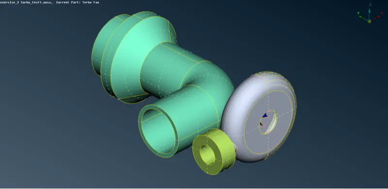
4. There are the additional surface areas of the attachment of the shat rotor and compressor casing and also the shaft rotor and turbo casing which need to be deleted and the edge needs to be projected and joined.
Step 3 -
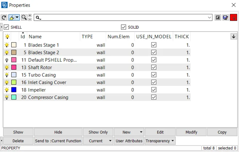
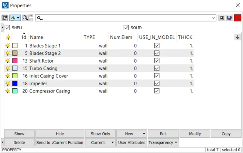
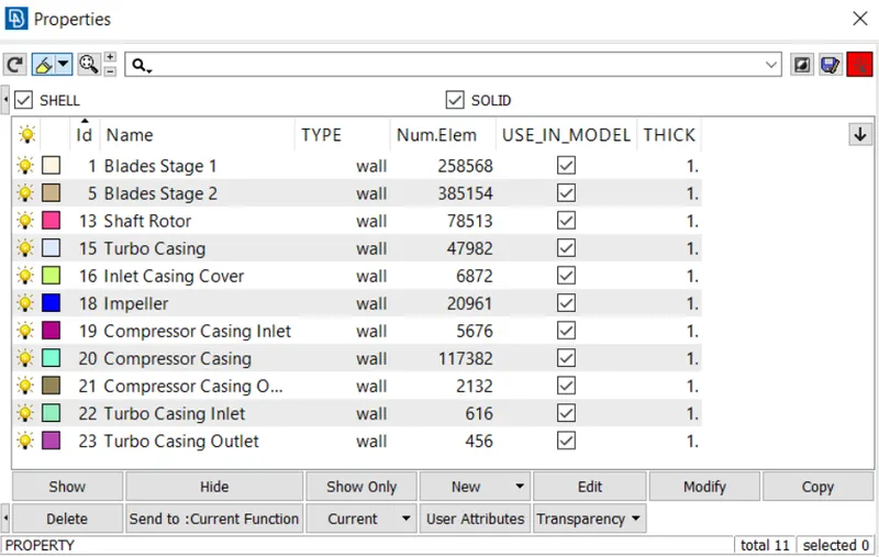
Assign the PIDs to the different parts of the model.
Step 4 -
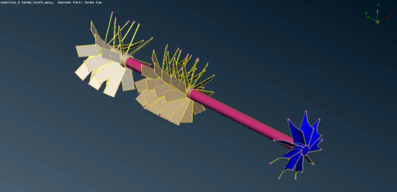
We need to combine the volume of the blade stage 1 and 2, shaft rotor and impeller. For that, we need to join the edges by using the "Topo" tool and then delete the additional common faces that are attached to the shaft rotor.
Step 5 -
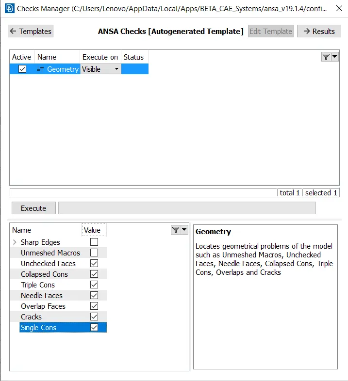
The Geometry check is performed to ensure that there is no error present in the geometry. Also, not that the triple con option is unchecked as we have a triple con in the model which are unavoidable.
Step 6 -
We need to compress the file using the "Compress" tool to ger rid of the unwanted faces, nodes, PIDs, etc.
B. Part 2 - Generating A Surface Mesh
Step 1 -
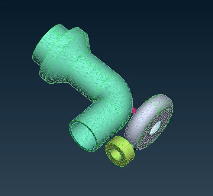
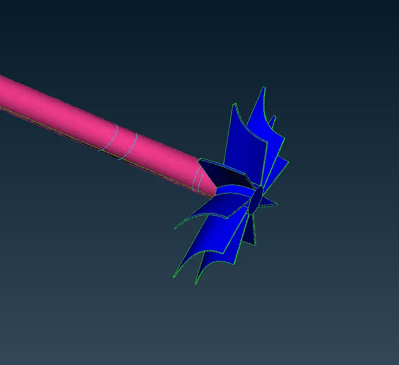
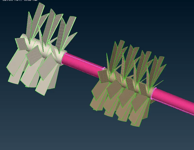
The required mesh size is assigned using the "Length" tool. The given model is meshed using the " Spot" mesh generation tool. The element type is "tria" and the reconstruct option is enabled.
The meshing of the model is done using different sizes on different PIDs as follows -
1. Blade Stage 1 - 1 mm
2. Blade Stage 2 - 1 mm
3. Compressor Casting - 5 mm
4. Impeller - 2 mm
5. Inlet Casing Cover - 5 mm
6. Shaft Rotor - 1 mm
7. Turbo Casing Cover - 5 mm
Step 2 -
The increase in the size of the mesh from one PID to the next attached PID can result in some parts that should have a small mesh size having a larger mesh size.
It is preferred that the part having a larger mesh size can have a reduction in size, but a part having a smaller mesh size should not go beyond the specified limit.
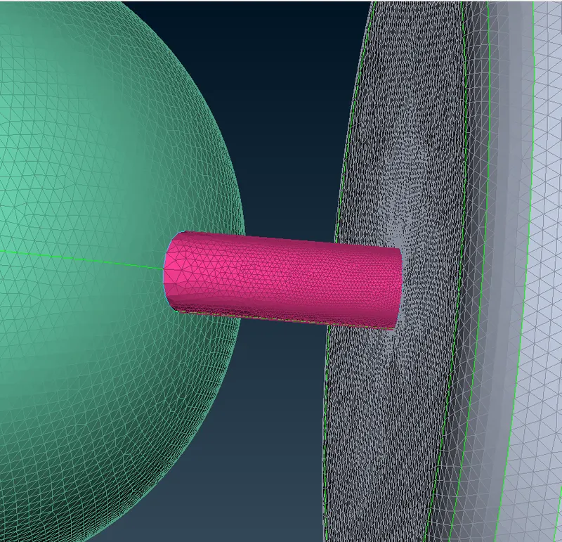
To fix this, we need to reassign the length of the PIDs having the inconsistency by using the "Length" tool and also enable the "Remesh Macros" option. Then we can simply re-mesh the parts to get an appropriate mesh.
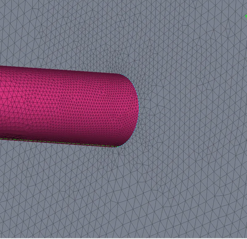
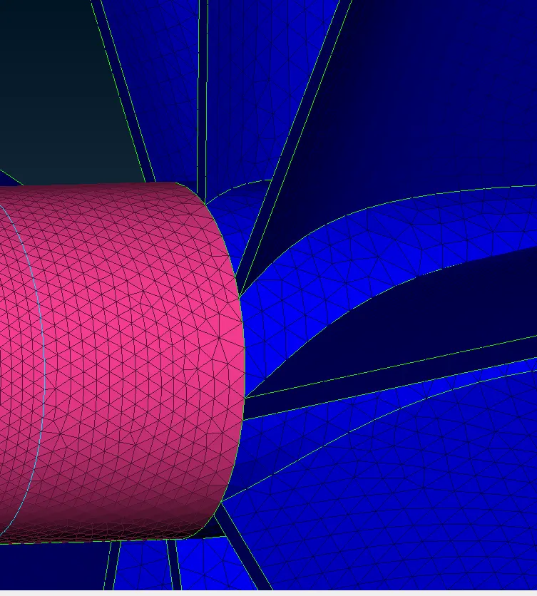
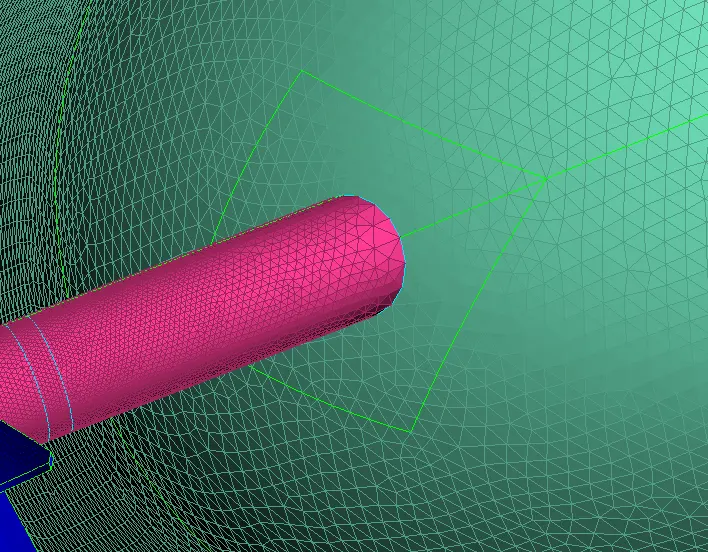
We can see that in one region there is a non - uniform distribution of the mesh on the compressor casing as there is an abrupt change in the mesh size.
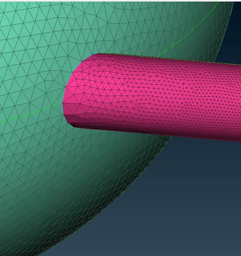
To ensure a uniform distribution of the mesh on the compressor casing, we can use the "Cut" tool to create a small patch around the region of connection.
C. Part 3 - Generating A Volumetric Mesh
Step 1 -
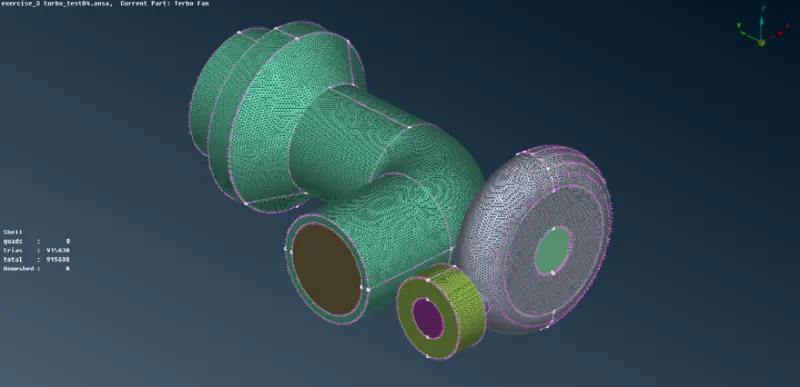
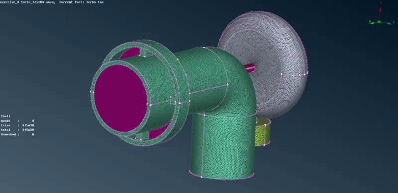
We need to close all the open faces to create a closed volume to further create a volumetric mesh. We can close the open regions by using several tools in the Topo mode such as "New Faces" and "Fill Holes".
Step 2 -
Assign the PIDs to the additional faces used to create a closed model.
Step 3 -
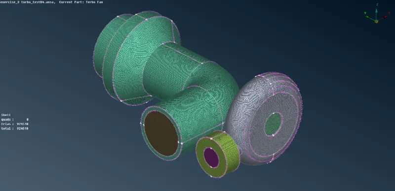
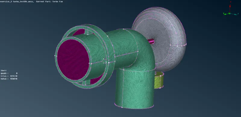
Generate a surface for the remaining surfaces using the "Spot " mesh generation tool.
Step 4 -
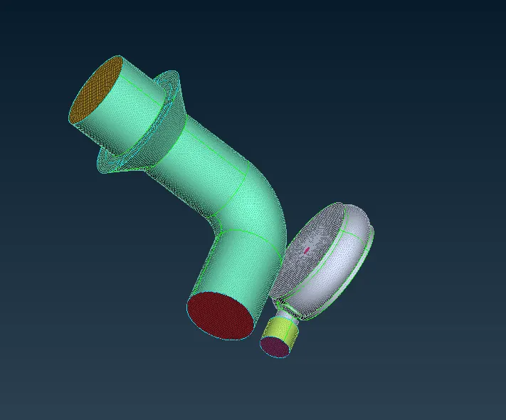
To create a volumetric mesh, we have to first create a volume element. For that, we have to use the "Define" Volume tool in the "V.Mesh" Module. This causes ANSA to automatically detect all the volumes that are present in the model.
We need to delete all the thickness volume as it is not required in the analysis. Also as there is no flow inside the shaft rotor, blade stages 1 and 2, and the impeller, hence, we can delete these volumes.
Step 5 -
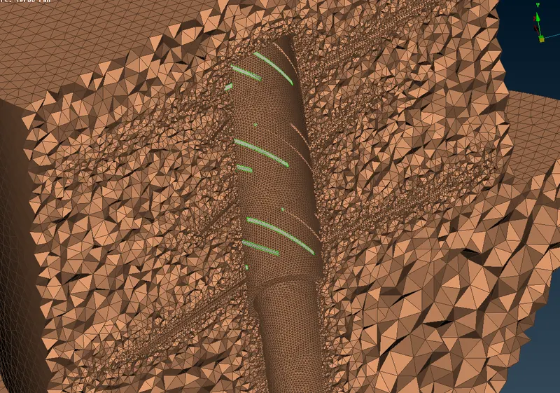
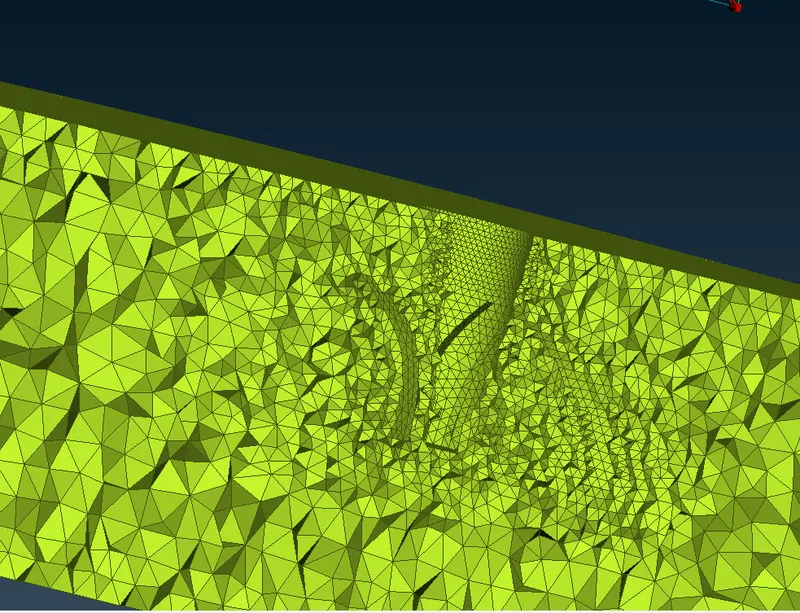
Finally, we have to create the volumetric mesh using the "Tetra CFD" tool.
We can see the interior part of the volumetric mesh by v=creating a small cut using the "Not" tool.
lll. CONCLUSION
The errors in the geometry are closed and the surface and the volumetric mesh have been successfully generated.