Week 3 Challenge : CFD meshing on Turbocharger
Objective - Surface and volume meshing on a turbocharger.
Introduction-
In an internal combustion engine, a turbocharger (often called a turbo) is a forced induction device that is powered by the flow of exhaust gasses. It uses this energy to compress the intake gas, forcing more air into the engine in order to produce more power for a given displacement. Turbocharger performance influences all important engine parameters, such as fuel economy, power, and emissions.
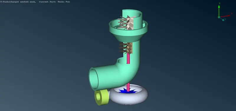
A turbocharger consists of a compressor wheel and exhaust gas turbine wheel coupled together by a solid shaft and that is used to boost the intake air pressure of an internal combustion engine. The exhaust gas turbine extracts energy from the exhaust gas and uses it to drive the compressor and overcome friction.
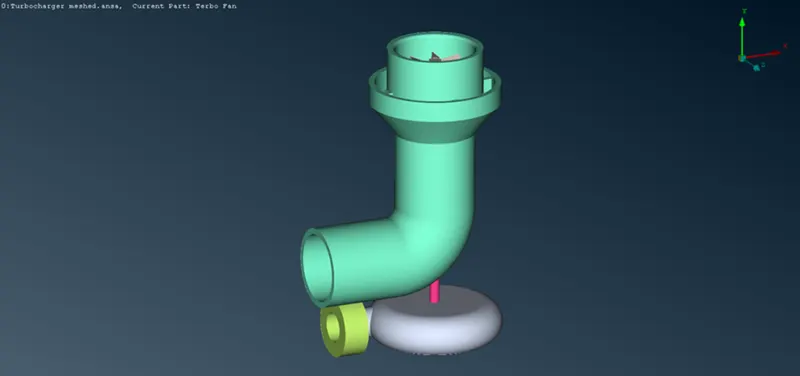
Below is the image of the turbocharger model-
Below is the image of cut section of the turbocharger which shows its compressor and turbine blades-
Procedure-
- First we have to rectify all the geometrical errors in the model before surface meshing. After the removal of all the geometrical errors, we can perform surface meshing. Also, we can perform volume meshing only after surface meshing the model.
Below is the image of turbocharger model with all the geometrical errors -
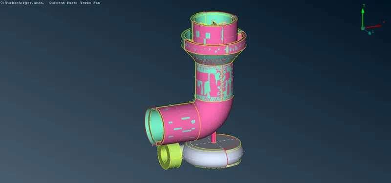
- So, initially we will perform topo on the model which rectifies and also shows some extra errors in the model by cleaning the geometry and joining the surfaces. Below model shows the model after topo is performed -
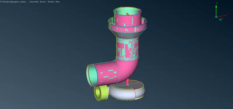
You can see the difference in the model after performing topo. Multiple triple cons have emerged due to overlapping surfaces which can be directly seen in the model. The overlapping surfaces are the surfaces which looks like a glitch in the model which is shown in above image as green and pink surface glitch.
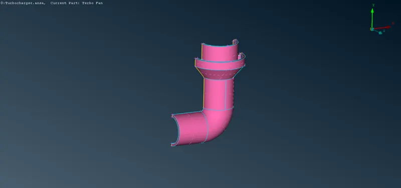
- We have to delete the pink surface since it is not the part of compressor casing ,i.e., green surface. We can directly exclude the pink surface by using 'or' tool and clicking the PID option and delete the whole pink surface. Below image shows the excluded pink surface.
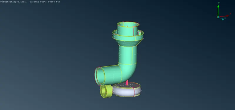
Below image shows the model after the above process execution.
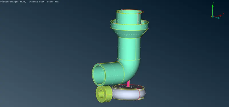
- Now, we are removing the single cons at the ouput of the compressor casing. We can do that by deleting the surface and making a new face at the same cons, which does not extend beyond the end, using the fill hole tool. Below image shows the model after the above tool execution-
- Now, we will remove the single cons at the top of the compressor casing by making new surface at the place. Since the surface is complex, we cannot directly patch up the surface in one go. Here we will use transform tool under the curves bar which copies a curve to the desired place.
Below image shows single cons at the top part -
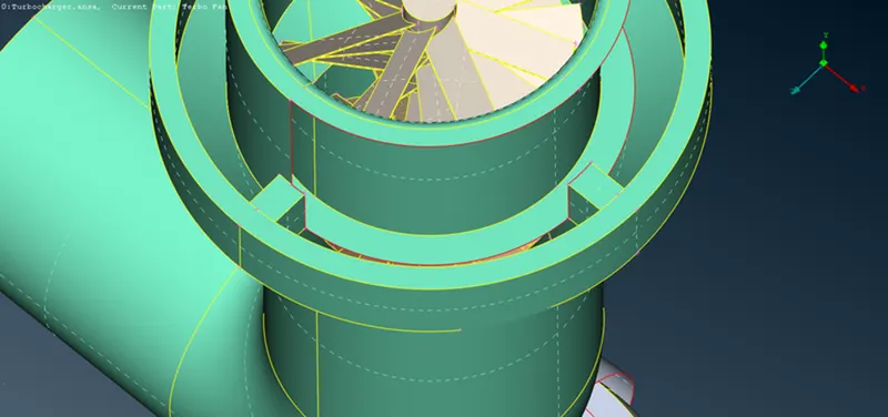
Below image shows the new curve, purple coloured, made by the transform tool-
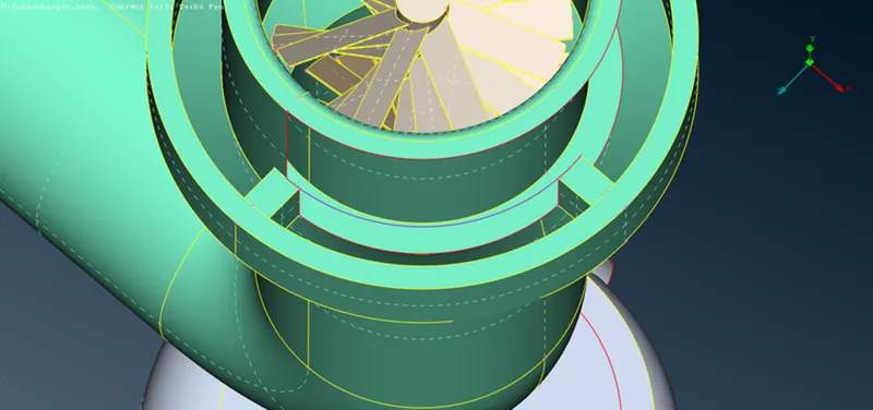
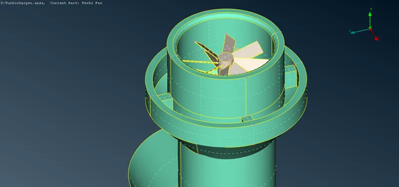
Similarly, make another curve at the neighbouring part. After that we can make new surface easily by uisng new tool under faces bar. Then, we can delete the curves since we have used them for making surfaces. Below image shows the new surfaces at the top part -
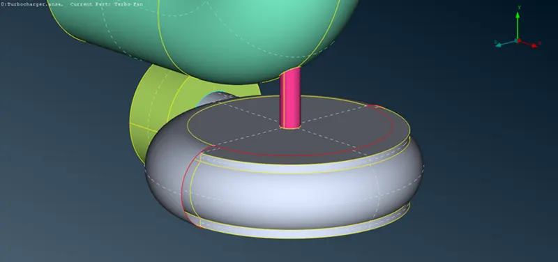
- Now, we can remove the single cons at the turbine casing at the bottom by making new surface. We can select 'copy' and use 'symmetry' option in the tranform tool in the utilities bar. Before that we have to make a hot point at the middle of side red curve to select '3 points mirror plane' option in the 'symmetry' option. It will make the surface by copying the opposite curved surface in a symmetrical manner. Below image shows the single cons and the curved surface at the opposite side -
Below image shows the new surface after using the transform tool -
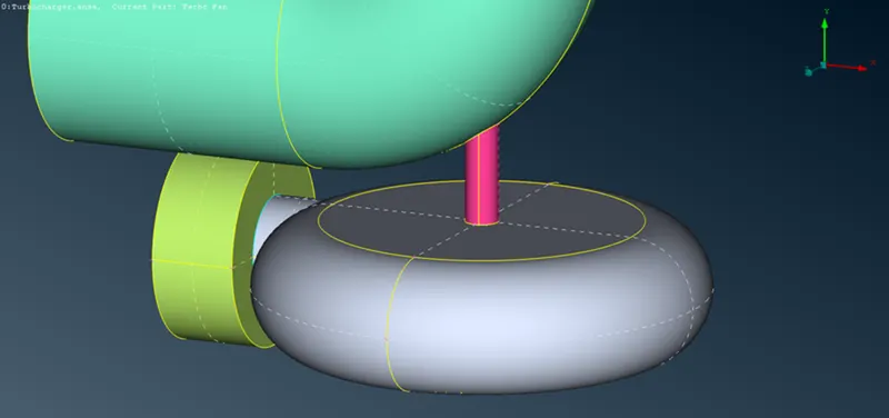
- Now we have to remove single cons inside the compressor casing which can be seen in wireframe mode as shown in image below-
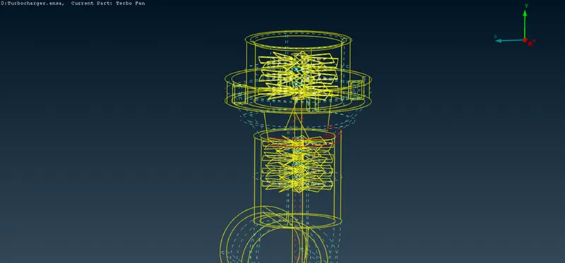
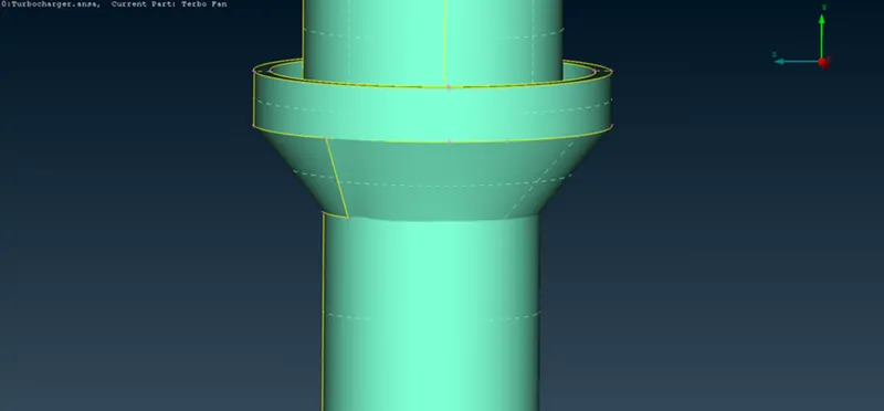
Here, we have to delete the extra surfaces which are extending and interfering each other by using 'intersect' tool under the 'faces' bar. The intersect tool directly gives the option of deleting the extra surfaces which are not suitable for the model. Below image shows the model after the execution of above process-
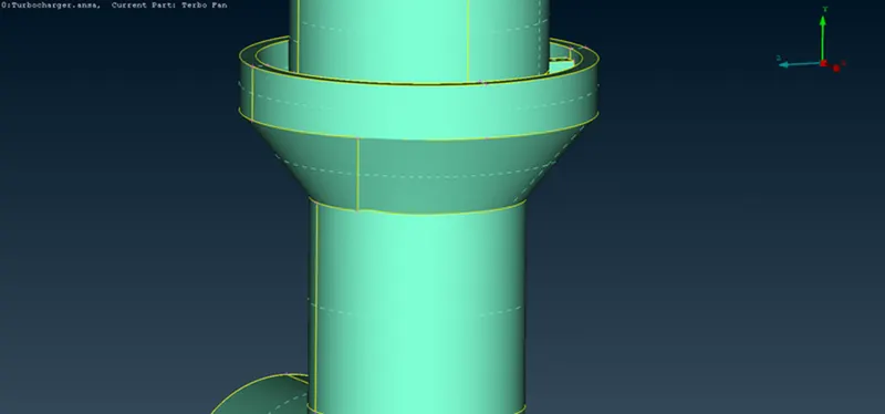
- Now, we can run a geometry check to check how many errors are left and where are the errors in the model. Below image shows the geometry check manager -
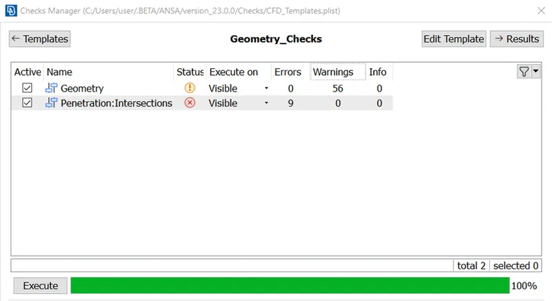
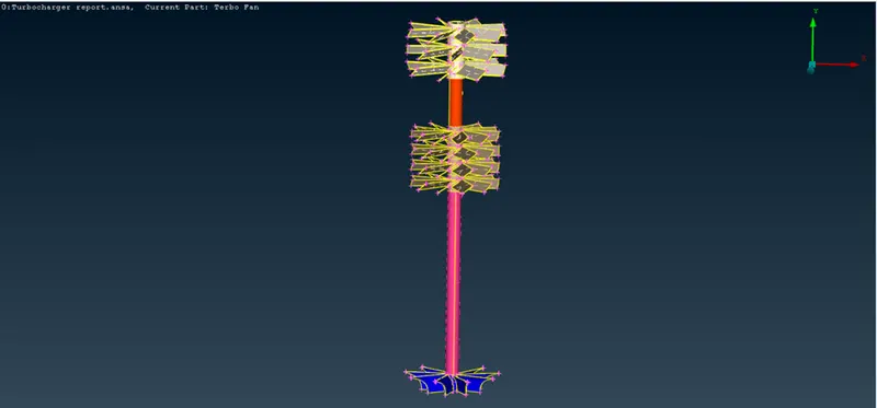
As you can see there are still many errors to rectify. Now we will first rectify the intersection and triple cons error in the shaft rotor. Below pic shows the shaft rotor-
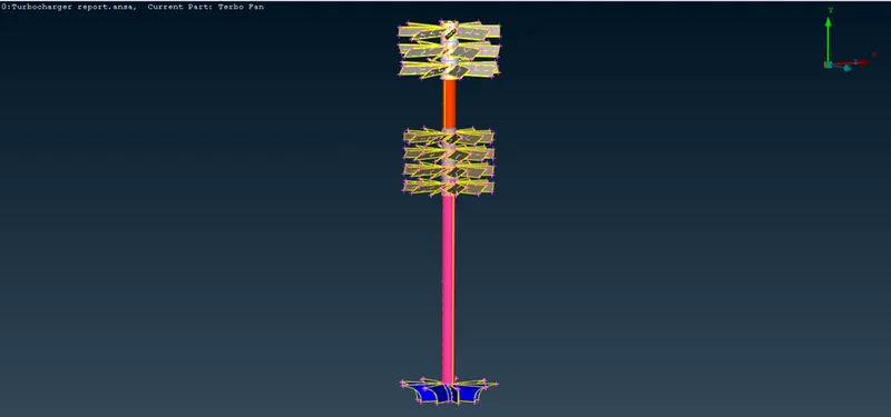
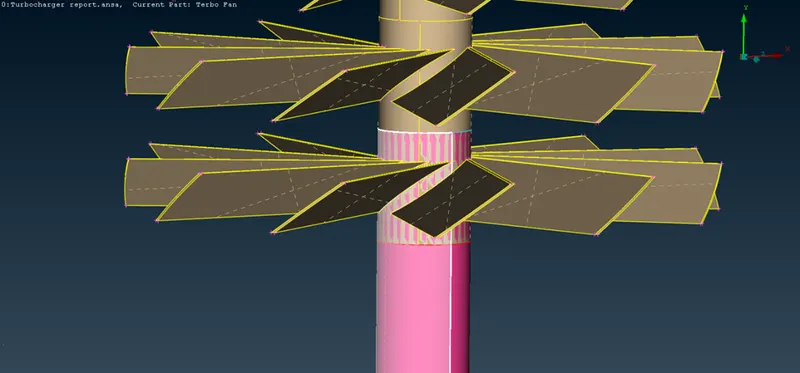
If you will see carefully there are triple cons and an intersection error on the shaft which we will remove by deleting the extra surface. For deleting the extended part of shaft which are intersecting with each other, we will use project con tool which divides the surface into two parts and then we can easily delete the intersecting part of shaft. The below image shows the intersection error and the selection of whole surface while selecting the surface for deleting -
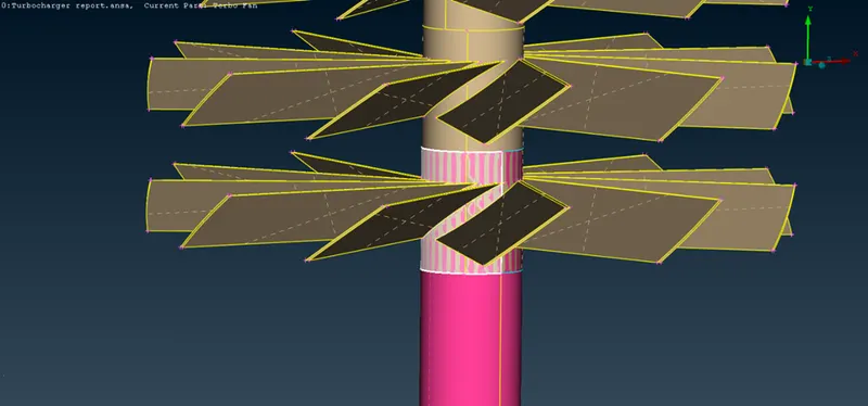
So, we need to use project con so that we can only delete the extra intersecting surface of the shaft which as shown below-
Similar to the above process we can use 'project' con tool at the bottom of the shaft to delete the surface and to remove the triple cons. Below image shows the shaft after removing the intersection error and the triple cons -
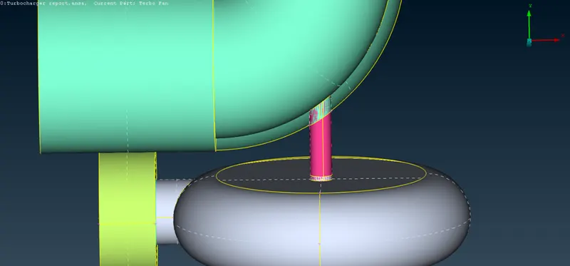
- Now, to remove the remaining intersection error as shown below we can directly delete the extra overlapping surface. The image below shows the intersection error in the model -
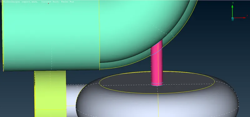
We can use project cons tool to project cons on the shaft to remove the single cons developed due to deleting the intersecting surface. The below image shows the model after removal of the intersection error-
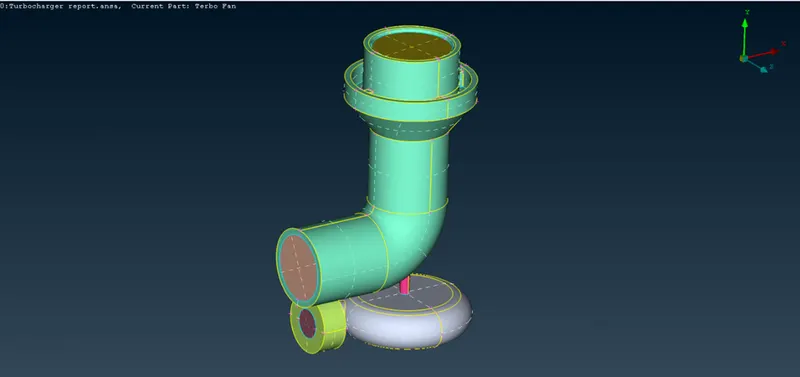
- After rectifying all the geometrical errors, we have to close the inlets and outlets of the model by creating a surface. This is important for volume meshing since it has to be closed for the mesh algorithm to detect the volume of the part. After that we can assign the PIDs for all the geometry. Below image shows the model before meshing -
- Target length for surface meshing for different PIDs are as follows-
- Blade stage-1 = 1 mm
- Blade stage-2 = 1 mm
- Impeller = 2 mm
- Shaft rotor = 1 mm
- Turbo casing = 5 mm
- Compressor casing = 5 mm
- Inlet casing cover = 5 mm
For surface meshing of similar target length, we will isolate the PIDs and perfrom meshing seperately. For example we will isolate turbo casing, compressor casing and inlet casing cover and perform meshing of target length of 5mm.
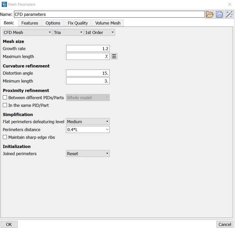
For surface meshing at target length of 5mm, we will first give mesh parameters of minimum and maximum length as 3mm and 7mm respectively as shown below. We have chosen element type as tria and mesh algorithm as CFD mesh.
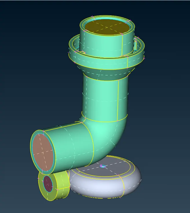
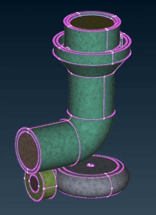
We will input same dimensions into the quality criteria. Now we will select the length tool from parameter bar to give length and macros to the given model by selecting the surfaces to be meshed which in this case is turbo casing, compressor casing and inlet casing cover. Below are the before and after meshing images of parts-
- Now for surface meshing of blade stage-1, blade stage-2 and shaft rotor at target length of 1mm, the mesh parameters will be as follows-
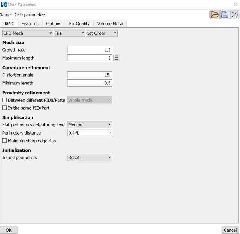
We will input same mesh parameters into the quality criteria. Below are the before and after meshing images of the parts-
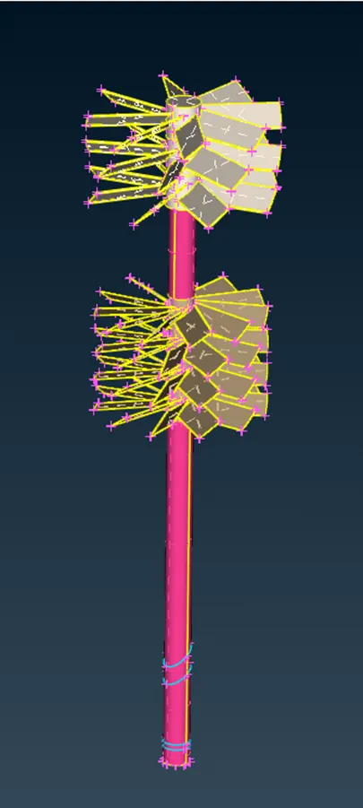
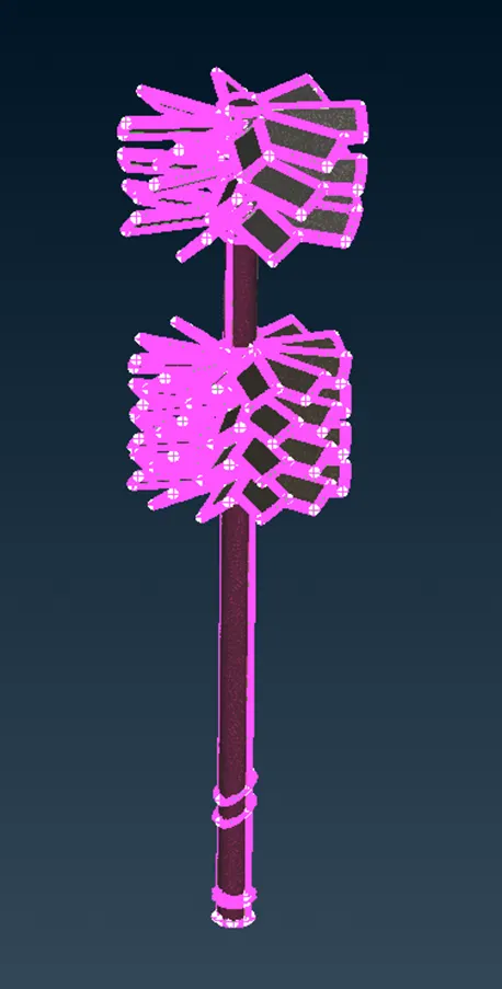
- Now for surface meshing of impeller at target length of 2mm, the mesh parameters will be as follows-
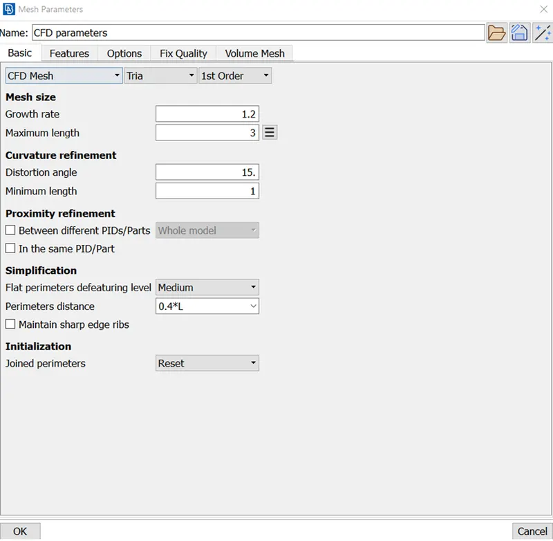
We will input same mesh parameters into the quality criteria. Below are the before and after meshing images of the parts-
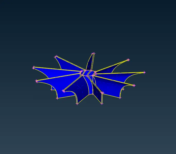
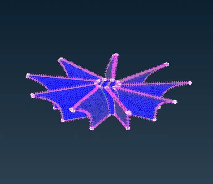
- Now, since we have done surface meshing of every part of the turbocharger model, we can now proceed to volume meshing. For that we first need to select define tool under volumes bar which auto detect volumes to be mesh. Below is the image of the list of auto detected volumes -
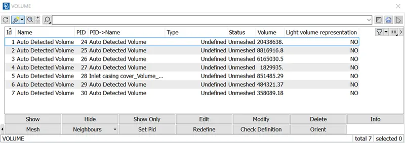
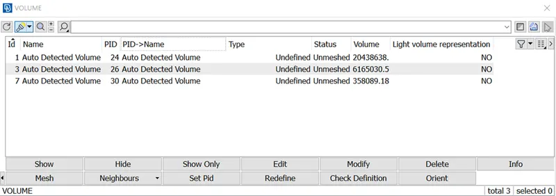
- Since we have to perform CFD simulation so we have to focus on the volumes in which fluid flow will happen, i.e., the inside volume of the model, excluding the volumes that consists of thickness of the model. So, we will delete the excluded volumes and perform volume meshing on remaining volumes. The below image show the final list of volume-
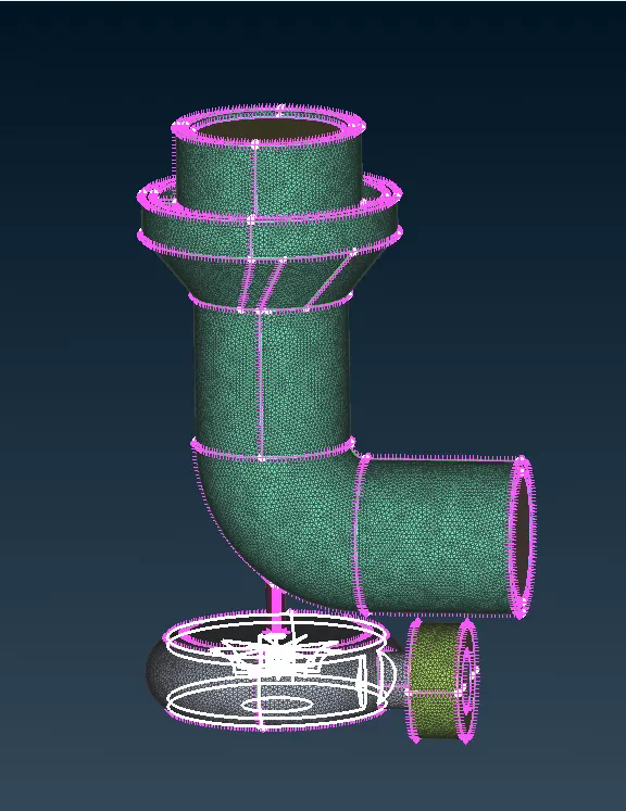
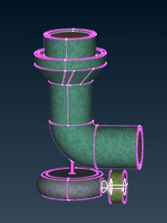
- Now, we will select the type of volume mesh to 'tetra CFD' by double clicking on the volume. Then we have to mesh each volume one by one. From the below image you can see the compressor casing volume, turbine casing volume and inlet casing cover volume respectively, which are to be meshed-
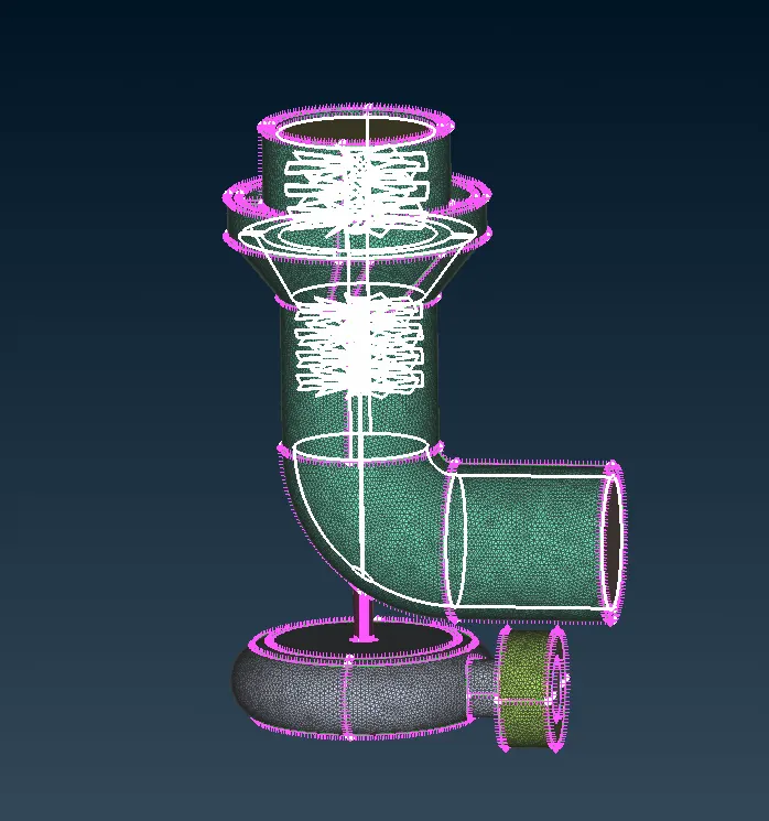
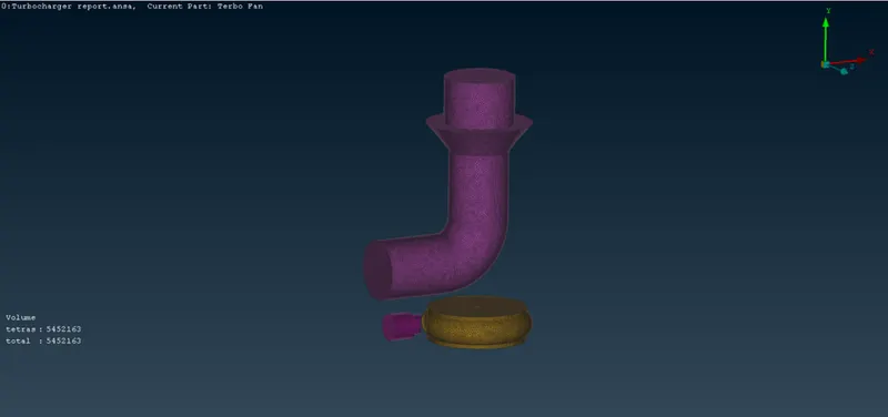
Below image shows the total meshed volume of the model-
Result-
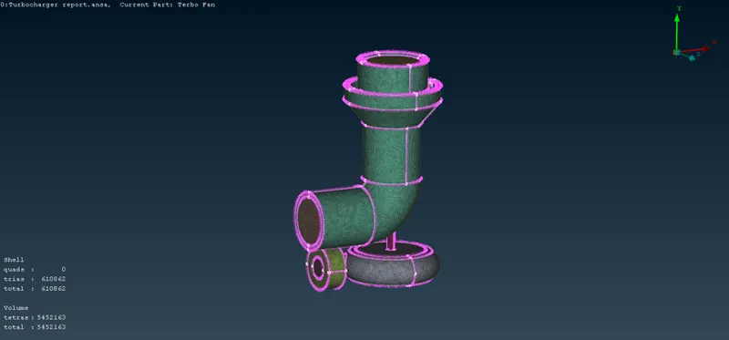
The final image of the surface and volume mesh of turbocharger is shown below. You can see the surface mesh element type is tria and the total number of tria elements are 610862. Also, you can see the volume mesh type is tetra and the total number of tetra elements are 5452163.