Project 1 : CFD Meshing for Tesla Cyber Truck
Objective- Geometric cleanup and CFD meshing of the TESLA cybertruck.
Introduction-
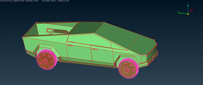
Below is the image of the Tesla cybertruck on which we have to perform geometric cleanup and CFD mesh-
Procedure-
- As you can see in the above image, there are lot of single cons. So we will have to use topo tool on the cybertruck. Below image shows the view after performing topo on it-
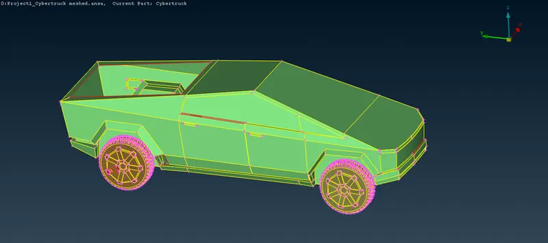
2. Now we can see some errors in the model. We will resolve those errors one by one. Below the parts show some single cons-
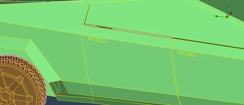
We will make new faces in the empty places to remove the single cons by using new tool under the faces bar. Below image shows the model after resolving above errors-
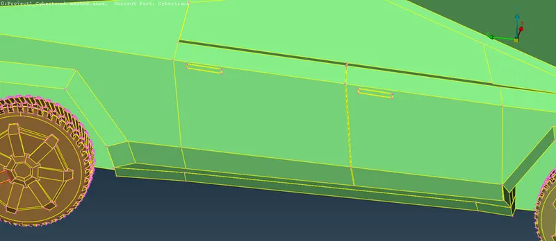
3. Similarly, we will make new faces at all the empty places where there are single cons to remove them. Below image shows the model after removing all the visible single cons-
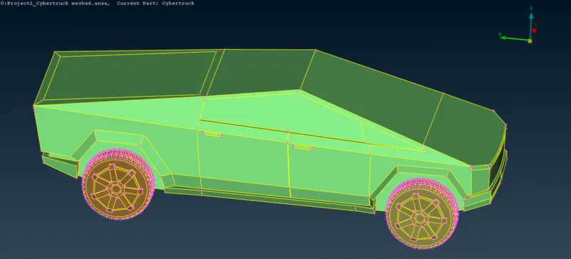
4. Now, we will perform geometry check to check the remaining errors in the cybertruck model. Below image shows the geometry check result-
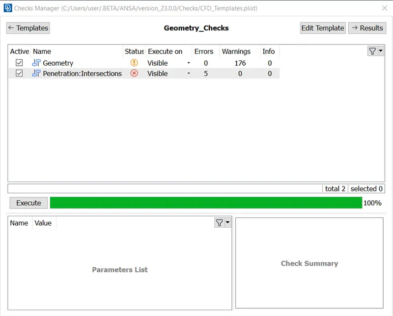
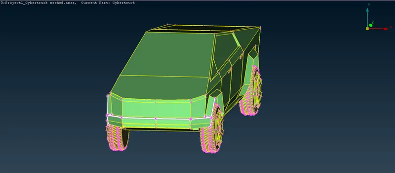
5. As you can see in the above image, there are 5 intersection errors. So, initially we will remove the intersection errors one by one. Below image shows the highlighted area where there is one intersection error-
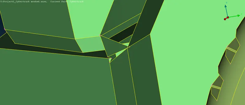
Now, we will hide some faces to see where there is intersection of surfaces so that we can resolve the intersection error. Below image shows the area of intersection error-
Now, there are many ways one can approach this to resolve the error. Either we can delete the intersected face and then make a new face in the place or we can make a cut to remove the intersected face then make a new face. So, below image shows the model after resolving the error-
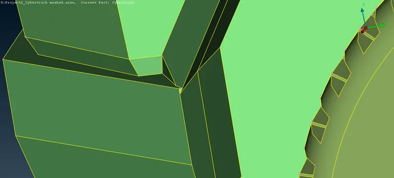
Performing the geometric check again shows the same intersection error on the other side. So we need to resolve the error in the similar way.
6. Now since we have resolved one intersection error, only four are remaining which are showing in the area shown in the image below-
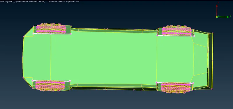
Now we will hide and check the intersecting faces. The intersecting area is shown in the image below after hiding some faces-
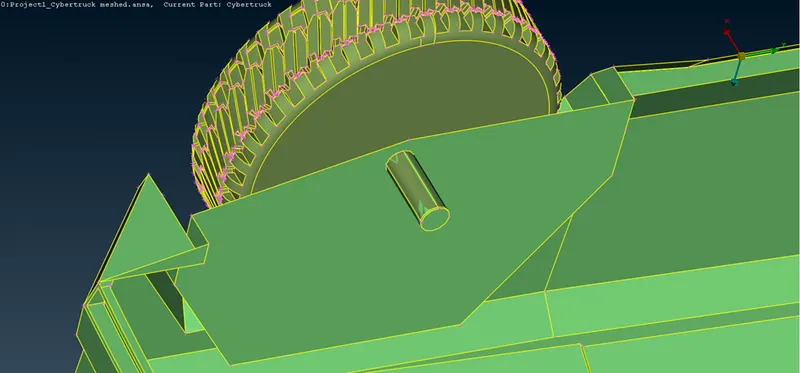
The four errors are similar and at same places, i.e., at the axle of the wheels. Now we need to delete the extra intersecting faces to resolve the error. Below image shows the model after deleting the intersecting surfaces-
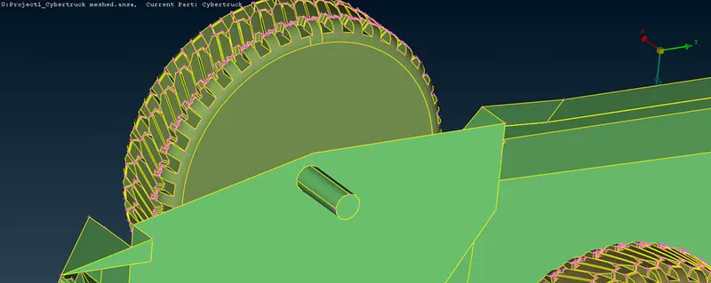
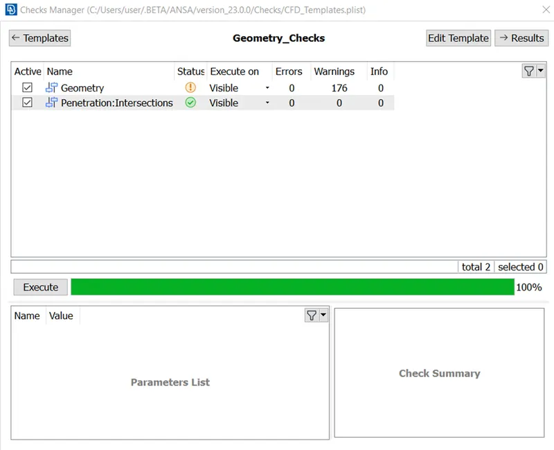
7. Now there are no intersection errors in the model as you can see below in the image of the geometry check-
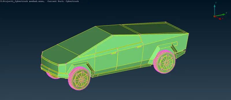
Now we will resolve some errors which are not directly visible like very small single and triple cons. Below image shows the final model of the cybertruck after resolving all the errors-
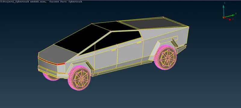
8. Now we will assign the PIDs to different faces and parts of the model. The PIDs are shown in the below image-
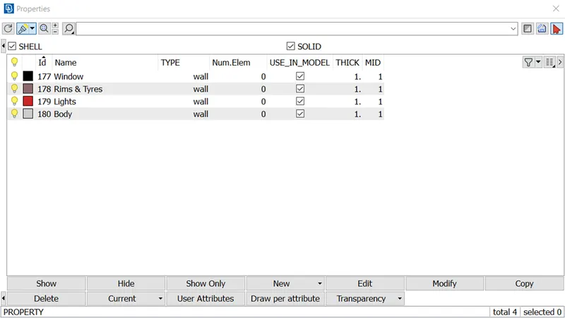
9. Now we will mesh the different parts of the car with specific quality criteria for each PIDs which are as follows-
- Body = 3mm
- Lights = 4mm
- Rims & Tyres = 2mm
- Window = 2mm
Along with these we will take skewness as 0.5. Now initially for rims, tyres and window, we have to take target length as 2mm. So, we will take maximum and minimum length as 2.5mm and 1.5mm respectively which is shown in the below image-
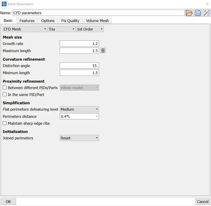
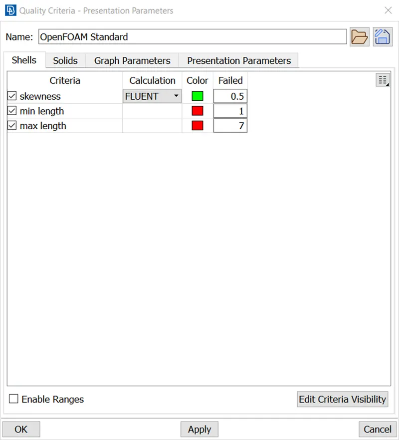
Inputs in mesh parameters are for individual PIDs whereas inputs in quality criteria are for every PIDs collectively. This means we will have to give mesh parameters for each PIDs while meshing whereas we only need to give inputs in quality parameters only once. So we need to give maximum and minimum lengths in quality parameters accordingly by taking every mesh target length in mind.
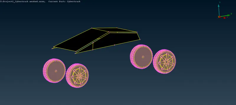
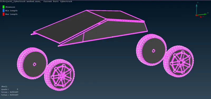
Below image shows the rims, tyres and window before meshing-
Below image shows the rims, tyres and window after meshing-
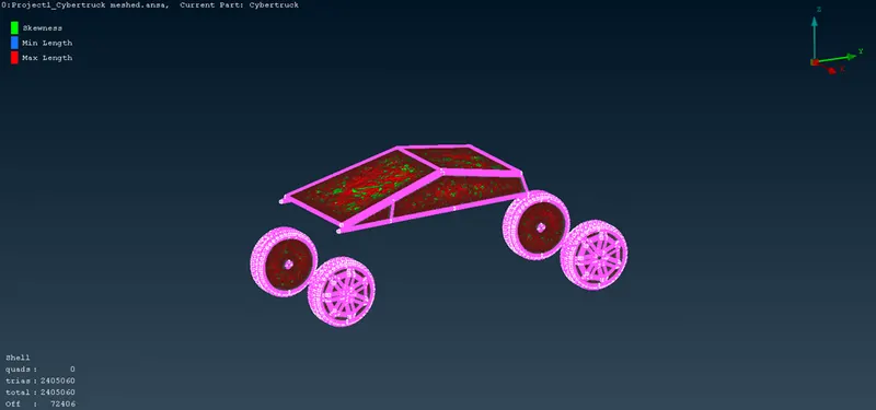
As you can see from the above image, there are off mesh elements which we can resolve by right clicking on the ‘off’ and click on improve. From there we have multiple options like reconstruct, reshape, smooth and fix quality which resolves the off elements. The below image shows the parts after resolving the off elements-
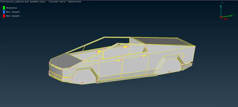
10. Now, we will mesh the body with target length as 3mm. So, we will take minimum and maximum target lengths as 2.5mm and 3.5mm respectively. The below image shows the body before meshing-
Below image shows the body after meshing-
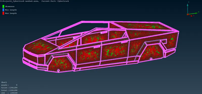
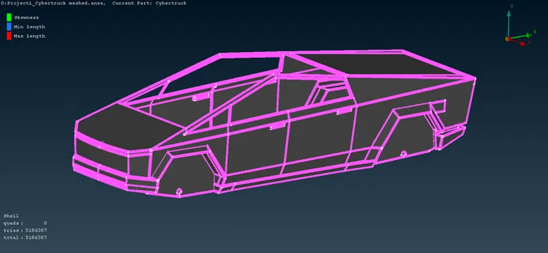
As you can see from the above image, there are some off mesh elements which we can resolve by the following the same process as we did in the previous meshing of tyres and windows. The below image shows the body after resolving the off elements-
11. Now we will mesh the lights with mesh element size as 4mm. So, we will take minimum and maximum target length as 3.5mm and 4.5mm respectively. Below image shows the lights before meshing-
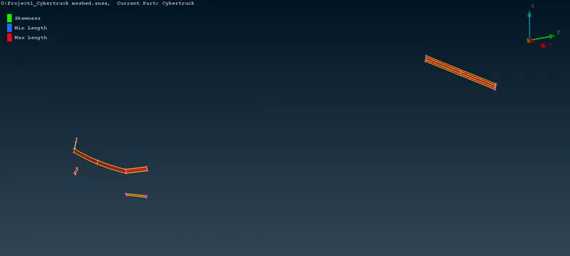
Below image shows the lights after meshing and removing the off elements-
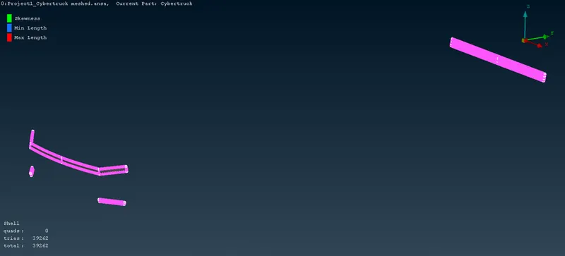
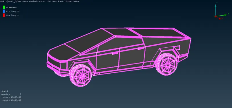
Below image shows the whole meshed cybertruck model-
12. Now we will create the wind tunnel, i.e., fluid domain around the Tesla cybertruck whose dimensions will be according to the parameters of the standard tunnel. The dimensions will be as follows-
- The front plane of the wind tunnel will be at a distance of 4 times the car length from the front of the truck.
- The back plane will be at a distance of 6 times the truck length.
- The top plane will be at a distance of 3 times the truck length.
- The side plane will be at distance of the truck length.
- The bottom plane can be taken at any distance with the only condition that it should not intersect with any part of the truck.
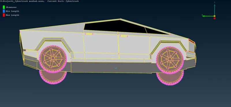
Now, to create the tunnel we will make nodal points using relative option in points tab and give the required distance in accordance with the above criteria. All the points will be created in relative with one nodal point which we will make at the bottom center of the cybertruck model.
Below image shows the nodal point at the bottom center of the model-
13. Now we will make different points at the front, bottom, back and top sides using the above point, which we will use to make the planes of the wind tunnel. Bottom image shows the different points on all sides-
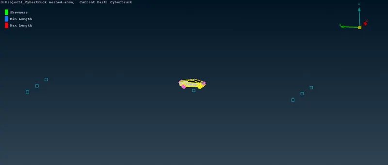
Now, using the points, we will create curves and then using the curves we will create faces. Below image shows the bottom plane created by using the curves-
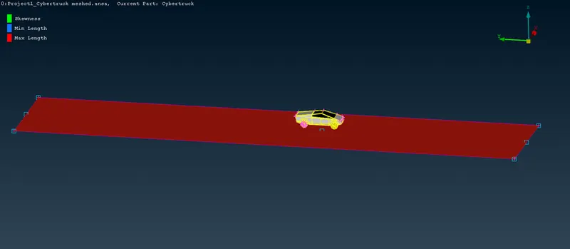
14. Now, we will make top plane by using offset tool and offsetting the bottom plane. Then we can create all the other sides using the new face tool. Below images show all the sides of the wind tunnel in shadow and wireframe mode-
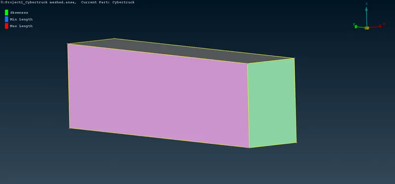
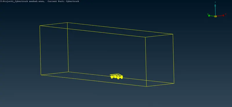
Now we will mesh all the sides of the wind tunnel by different mesh sizes. The element size for each planes are shown below-
Bottom plane- 20mm
Top plane- 100mm
We will use manual spacing tool on the side planes by selecting the 4 side cons, which will mesh the side planes in an increasing or decreasing manner of element size. We will mesh the side planes in this way which will increase the mesh element size from 20 to 100 from bottom to top plane. The inputs in the manual spacing is shown below-
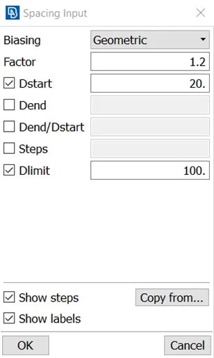
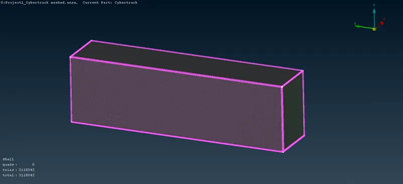
Below image shows the meshed wind tunnel-
Google drive link- https://drive.google.com/file/d/1DYAKQQ_lV58_e4s20BihohqQfinB_kiR/view?usp=sharing