Week 4 Challenge : CFD Meshing for BMW car
Objective- Geometric cleanup and CFD meshing of a BMW car.
Introduction-
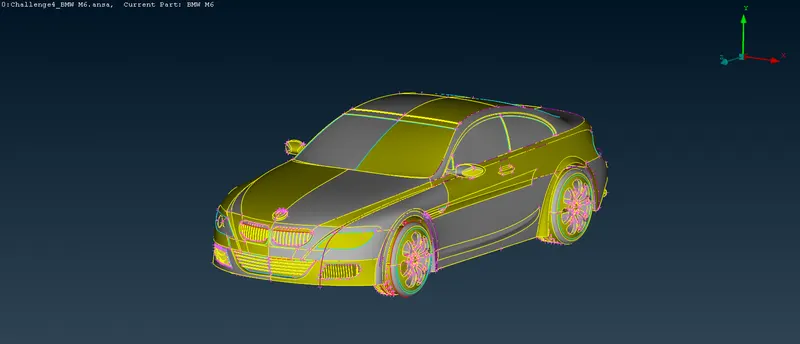
Below is the image of the BMW car model-
Procedure-
- Initially we have to rectify all the geometrical errors in the model before surface meshing. As you can see the image above, there are multiple errors in the model and we will remove the errors by focusing on each part of model one by one.
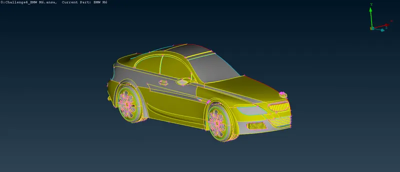
- Since the car is symmetric therefore we can delete half of the model and perform geometric cleanup and meshing on the rest. After meshing the half part we can use symmetry tool to make the whole model of the car. Below image shows the half part of the car-
3. Now, for volume meshing and analysis we want to make the whole inside volume of BMW car as a single volume and thus we will remove unnecessary surfaces and volumes which can create individual volumes. Also, we will remove errors in the process.
4. First we will take one of the front grills for geometric cleanup which is shown in the image below. The first image shows the front view of the grill, second image shows the back view of the grill and third image shows the zoomed back view of the grill after hiding the back surface. As you can see from the back view of the image, the grill will form a separate volume, which we do not want to happen.
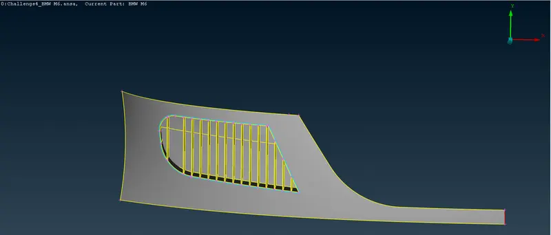
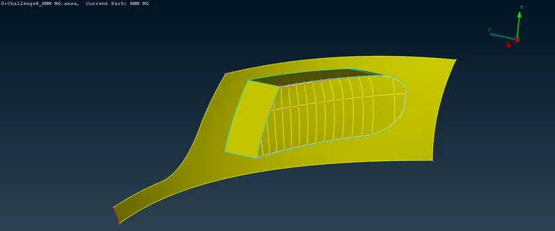
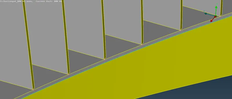
Since the grills are not aligned, we will have to fix it. For that we will create a surface just inside the back surface so that we can use intersect tool for deleting the unnecessary and non-aligned surfaces. We will need to assign the PIDs for the existing grill before creating the new surface. The surface created is shown below-
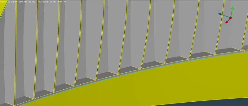
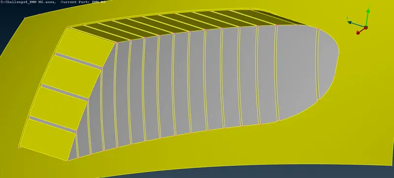
Now, assign the new surface a new PID and then we can use the intersect tool for deleting the non-aligned surfaces at the back part of the grill. The final image of the grill, after deleting the unnecessary surfaces, is shown below-
5. Now, we will select second grill in front of the BMW car for geometric cleanup. The front and back view of the grill is shown below-
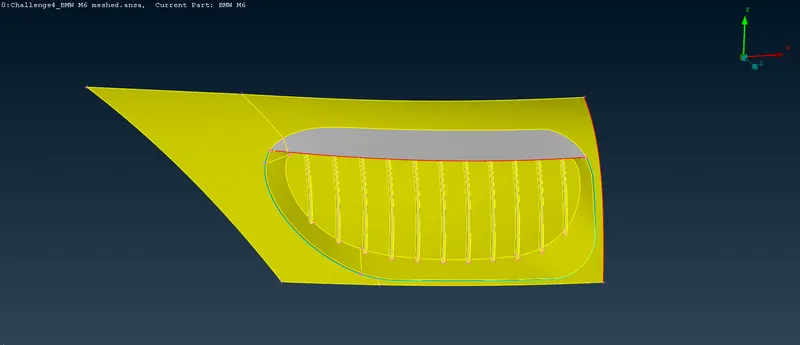
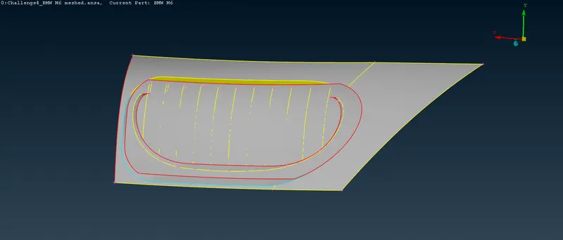
Here also it will create separate volumes in volume meshing. So, we will have to fix the surface from the back side of the grill. The zoomed image of the grill is shown below-
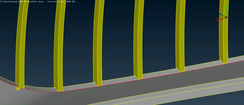
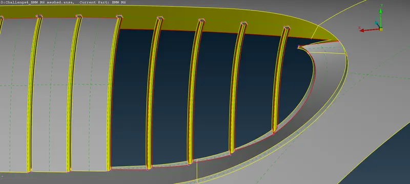
Since the grills are not aligned, we will have to fix that by making cut on the surfaces and also we will have to delete the back surface of the grills so that it can be made into a single volume. After that we will close the back side by creating a surface using new surface tool. The image using the above process is shown below-
Now, after creating the surfaces we will close the top side of the grill. For that we can use project tool but since there are many surfaces of the grills so we will have to select all the surfaces one by one which a hectic process. So, instead of that we will use plane cut tool using 3 points, which cuts all the surfaces of the grill in one go. It is shown in the image below-
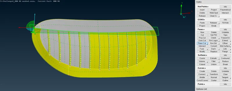
The result of the above plane cut tool is shown in the image below. You can clearly see the cut line on all the surfaces of the grill.
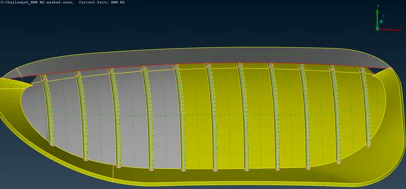
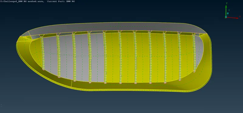
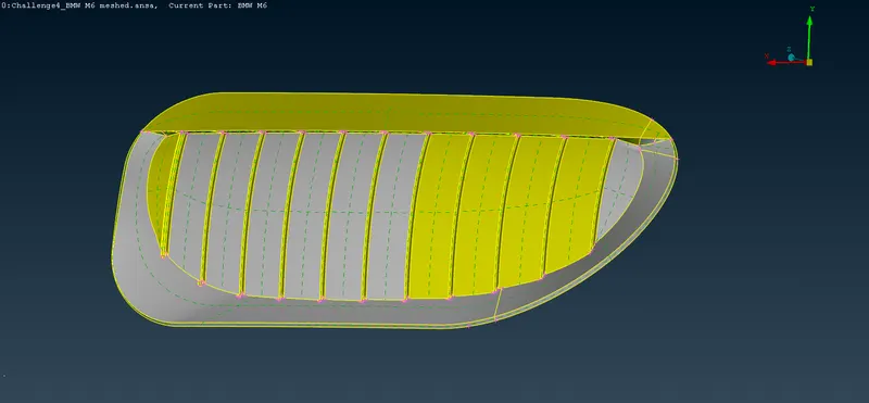
Now, we will delete the surfaces of the grill above the cut line and close the surfaces on the top with the above grill cover surface. That can be done by inserting hot points and using new surfaces tool. The final result of the grill is shown in the image below which shows the front and back view of the grill.
6. Now, we will select the last grill in front of the BMW car for geometric cleanup. The front and back view of the grill is shown below-
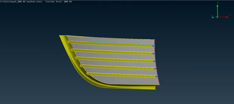
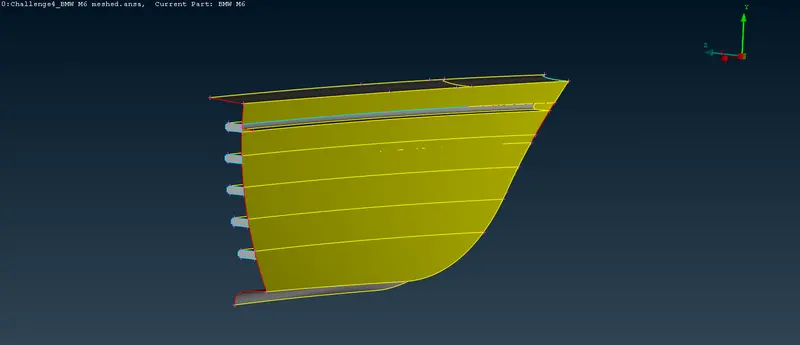
Here also it will create separate volumes in volume meshing. So, for fixing that we will have to delete the back and side faces of the individual grills without removing the main surface. For achieving this task we will have to project the cons on to the main surface as shown in below image-
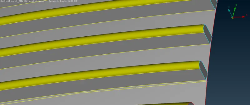
After this we will remove the side face which is above the surface and make a new surface using the projected con. This will allow us to delete the face on the base so that we can achieve our aim of creating a single volume. The new improved face is shown in the below image-
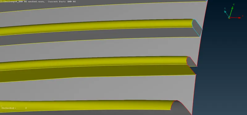
As you can see from the above image, the new face is on the base surface unlike the previous face which was above it. Now, we will use the same process for all the other grill. The final image of the grill is shown below-
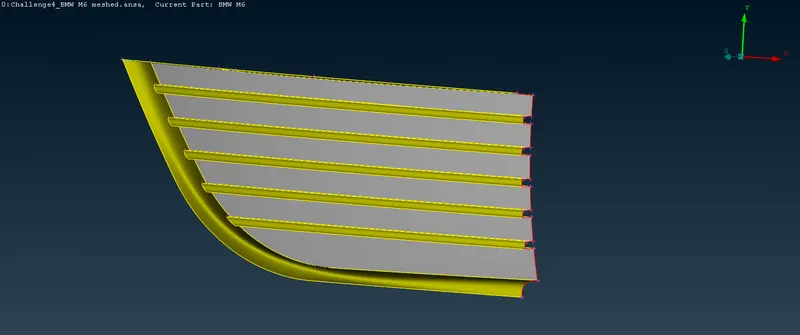
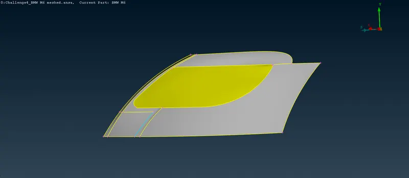
7. Now we will remove errors in the front headlights. The front and back image of the front headlights is shown below-
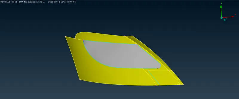
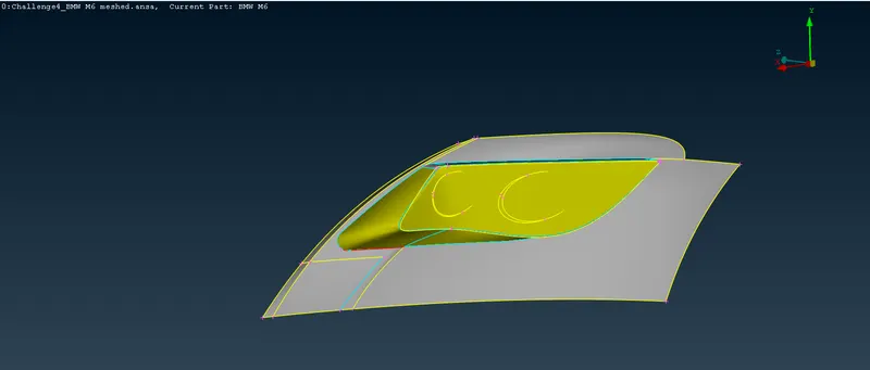
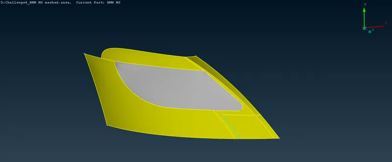
As you can see in the image above, it has multiple triple cons and some single cons. But since all that is covered by a front surface so we don't need the below surfaces since we need single volume of the BMW car. So, we can directly delete all the inside surfaces. The final image of the headlight is shown below-
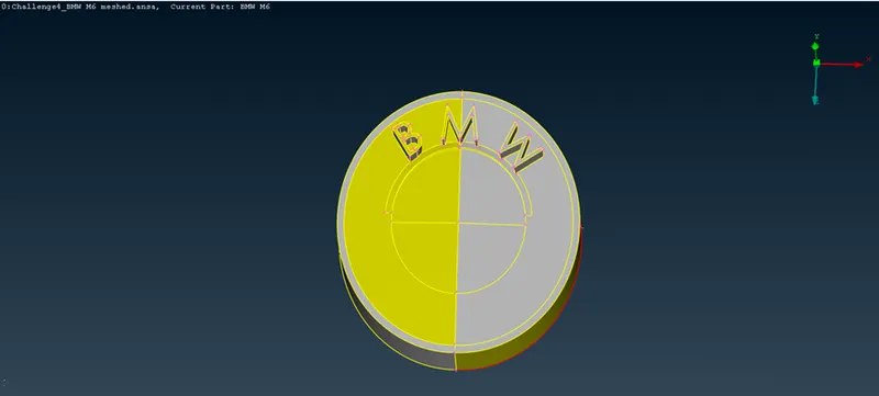
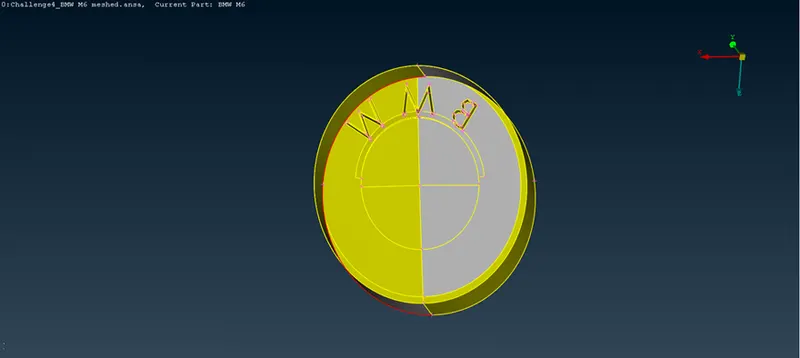
- Now, we will remove some errors in the logo of the car which is shown in the image below. If you look at the geometry check in the image below, you can see the respective errors that we have to resolve.
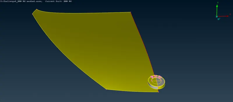
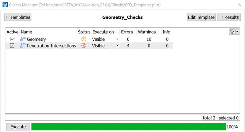
The intersection errors will be removed by deleting the overlapping surfaces and intersecting surfaces and making new surfaces at the required places. As you can see in the back image of the logo, we will have to delete the surfaces at the back so that it does not form individual volume.
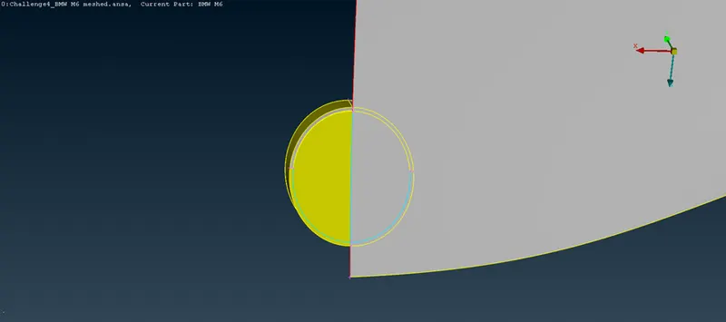
The final image of the logo without any errors is shown below-
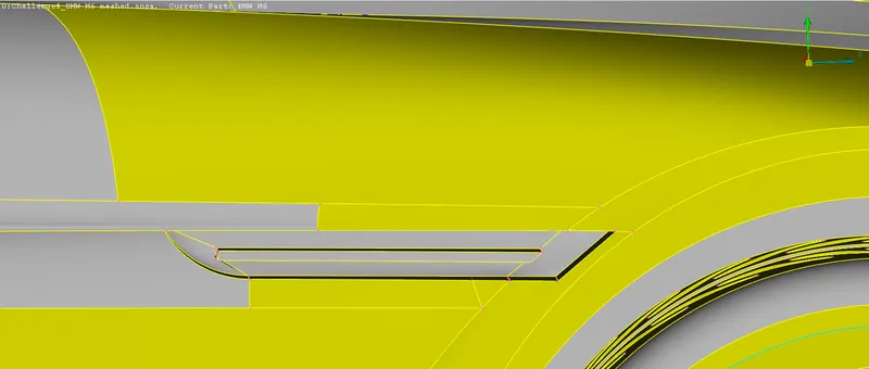
9. Now, we will take a look at the side parts of the car for errors and resolve it. You can see the outside and inside image of indicator at side of the car which has several errors which is shown below-
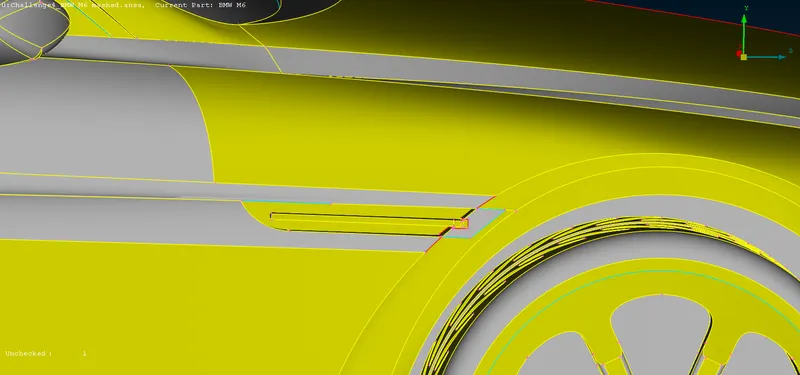
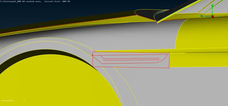
We can directly delete the intersecting surface and try to remove the red cons by using several tools like cut, project, extend and new face tool to make new surface in the place of deleted face. The extend tool only works on the single cons. Below image shows the indicator after resolving the errors-
10. Now, coming to the front windshield where there are some triple cons as can be seen from the below image-
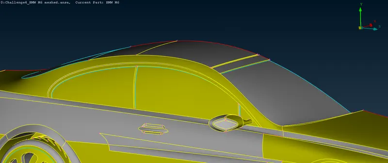
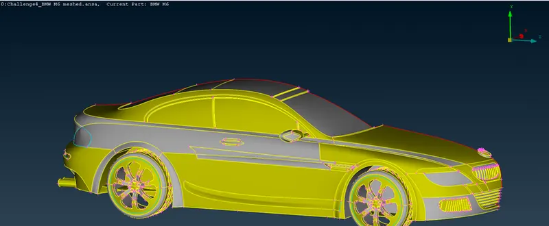
We can directly delete the top surface and side surface connecting it to resolve the triple cons. Similarly, we can delete the surfaces in from the back windshield to remove the triple cons and also from the side windows. The image showing front and back windshields without errors is shown below-
11. Now, we will do geometric cleanup on the rear view mirror part. As you can see from the image below, there are many triple cons so we will first clear that and after that we will proceed further.
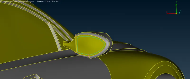
We will remove the triple cons by deleting the multiple surfaces and later on make one surface instead of the multiple surfaces. As you can see from the image below that the it will form separate volume and also an intersection error, so we need to delete the surface by projecting the circular cons at the end.
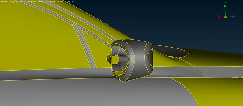
The final image of the rear view mirror part after geometric cleanup is shown below-
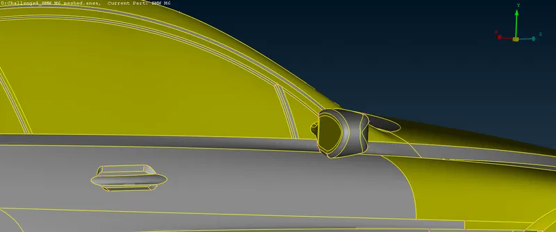
12. Now we will do geometric cleanup of the base of the BMW car. As you can from the side view of the car in the image below, there are many unnecessary surfaces protruding and intersecting the wheels.
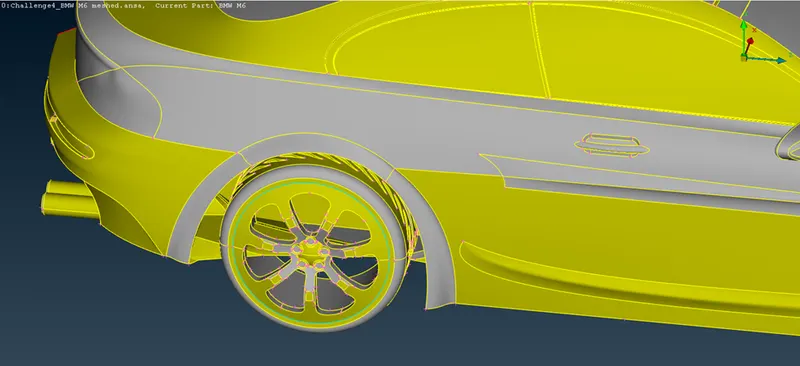
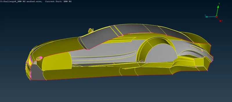
Before deleting any faces on the base of the car we need to use cons to curve tool on the middle cons of the car so that we have an outline of the cons in the form of curves. This helps us to make new faces at the same place without any issue. Below image shows the result after using the cons to curve tool-
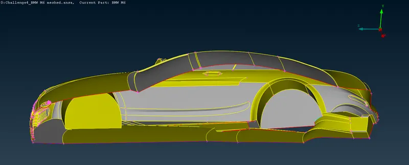
So, now we need to delete the intersecting surfaces properly and make new faces where it is necessary. Below image shows the side view after removing the necessary surfaces.
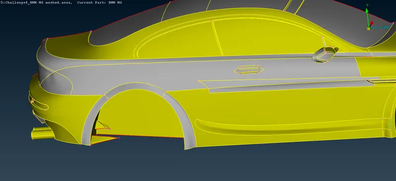
Now, as you can see from the image above, the surfaces are intersecting and since we can’t directly delete the whole face so we will use intersect tool to delete the protruding faces. The image below shows the side view after deleting the faces-
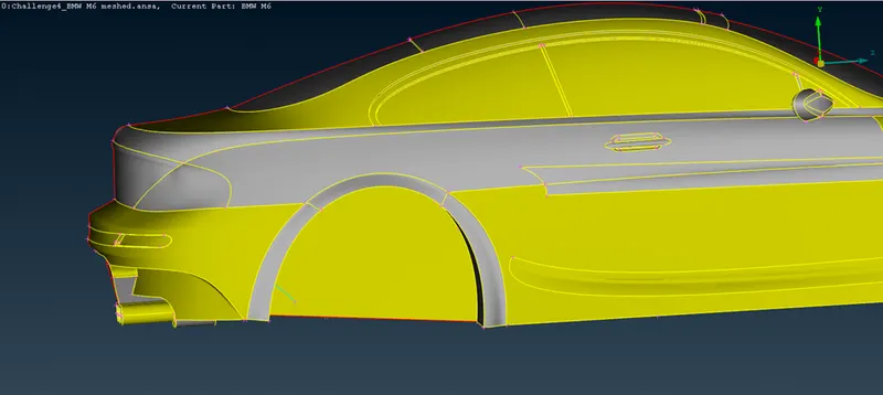
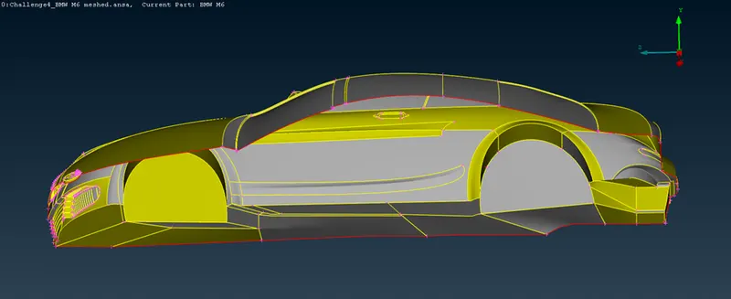
Similarly we have to cleanup at the front. The final image of the base of the car after geometric cleanup is shown below-
13. Now, we will perform geometric cleanup on the wheels. Below image shows the wheels-
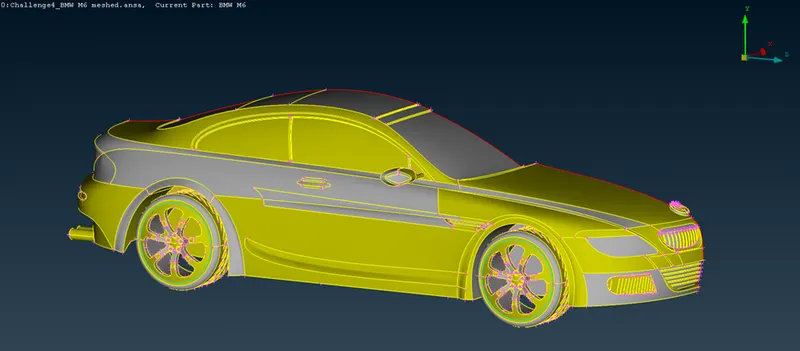
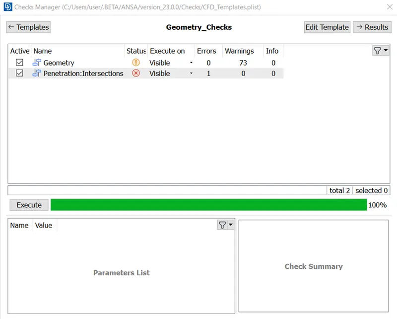
As you can see in the geometry check above, there are triple cons as well as an intersection error in the wheels which we will have to remove. Below image shows the final image of the car with no errors-
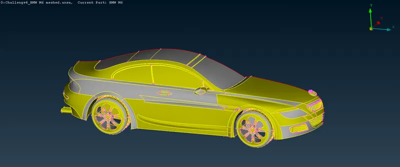
14. Now we will assign the PIDs to different surfaces and parts of the car. The PIDs are shown in the below image-
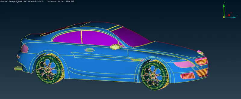
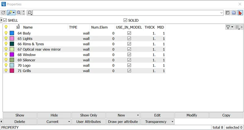
15. Now we will mesh the different parts of the car with specific quality criteria for each PIDs which are as follows-
- Body - 3 mm
- Lights - 4 mm
- Grills - 1 mm
- Rims and Tyres - 2 mm
- Optical Rear view mirror - 2 mm
- Window - 2 mm
- Silencer - 3 mm
- Logo - 1 mm
Along with these we will take skewness as 0.5. Now initially for logo and grills we have to take target length as 1mm. So, we will take maximum and minimum length as 1.5mm and 0.5mm respectively which is shown in the below image-
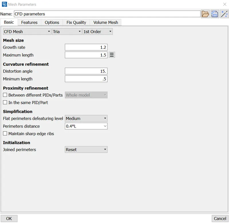
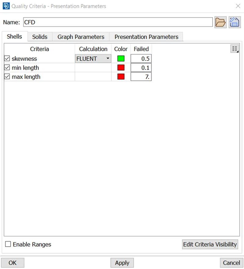
Inputs in mesh parameters are for individual PIDs whereas inputs in quality criteria are for every PIDs. This means we will have to give mesh parameters for each PIDs while meshing whereas we only need to give inputs in quality parameters only once. So we need to give maximum and minimum lengths in quality parameters accordingly.
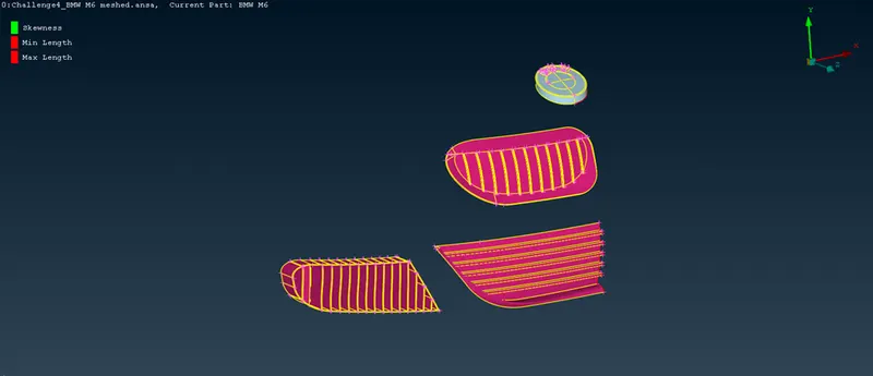
Below image shows the logo and grills before meshing-
Below image shows the logo and grills after meshing-
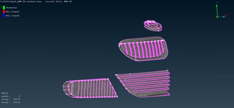
16. Now, we will mesh the rims, tyres, windows and optical rear view mirror with target length as 2mm. So, we will take minimum and maximum target lengths as 1.5mm and 2.5mm respectively. The below image shows the parts before meshing-
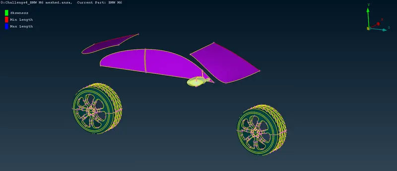
Below image shows the rims, tyres, windows and optical rear view mirror after meshing-
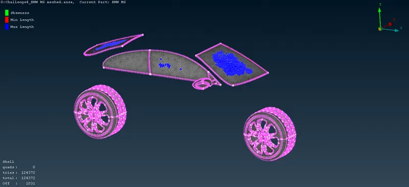
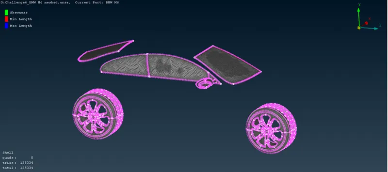
As you can see from the image above, there are some off mesh elements which we can resolve by right clicking on the ‘off’ and click on improve. From there we have multiple options like reconstruct, reshape, smooth and fix quality which resolves the off elements. The below image shows the parts after resolving the off elements-
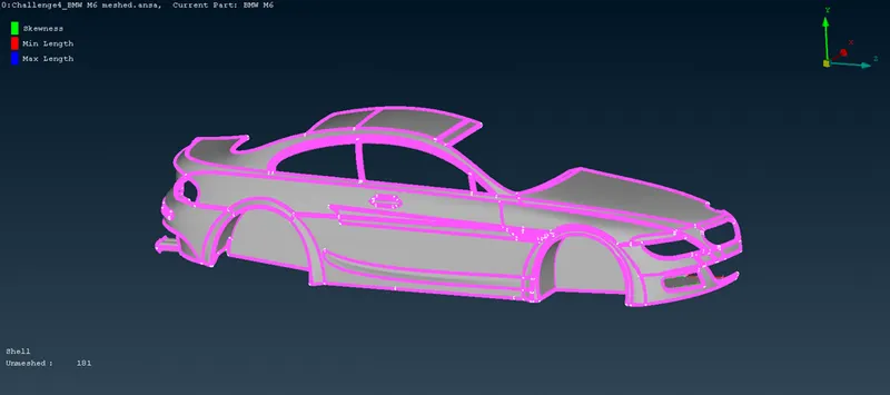
17. Now we will mesh the body and silencer with mesh element size as 3mm. So, we will take minimum and maximum target length as 2mm and 3.5mm respectively. Below image shows the body and silencer before meshing-
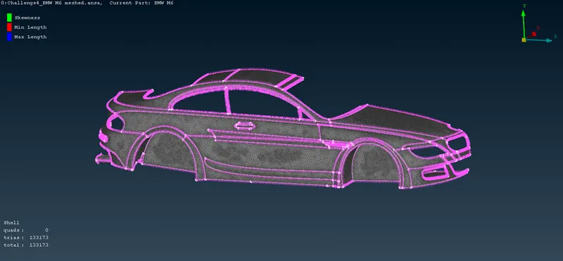
Below image shows the parts after meshing and removing the off elements-
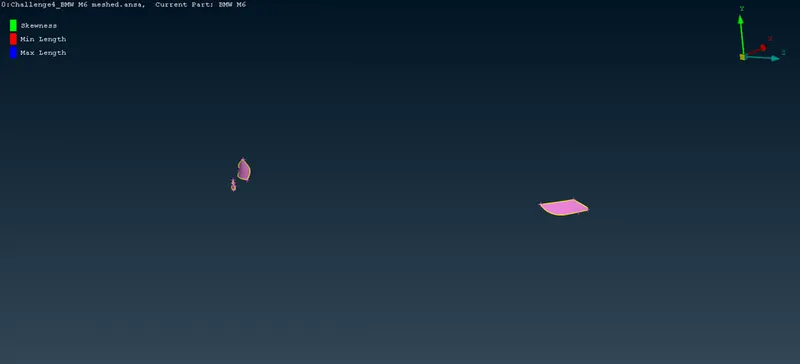
18. Now, the last part, lights, is to be meshed with mesh element size as 4mm. So, we will take maximum and minimum element size as 4.5mm and 3.5mm respectively. Below image shows the lights before meshing-
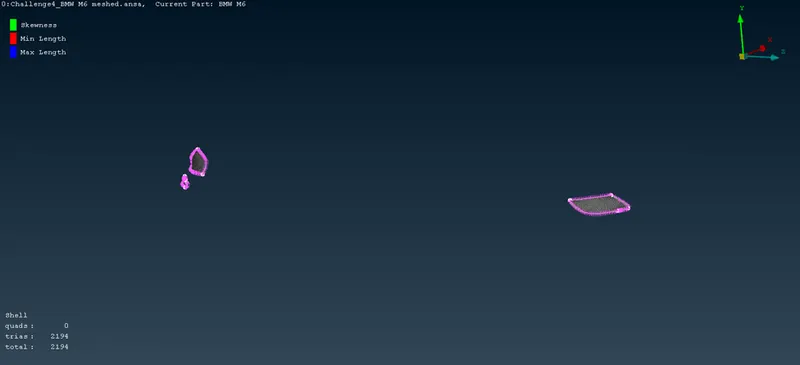
Below image shows the lights after meshing-
Below image shows the whole car after meshing-
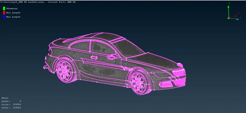
19. Now, we will make the other half of the car using symmetry option in the transform tool. We will use 3 points plane option for the symmetry by selecting 3 hot points in the middle plane of the car. Below image shows the final image of the car after using symmetry tool-
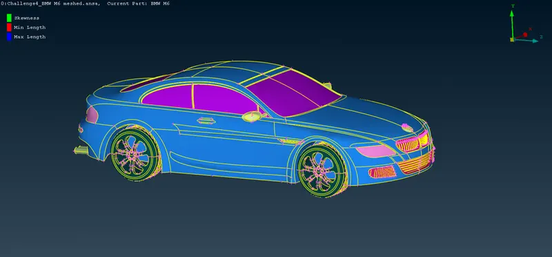
There was unmeshed faces after the creation of the other half of the car which we have to again mesh with the same quality criteria. Below image shows the whole car after meshing-
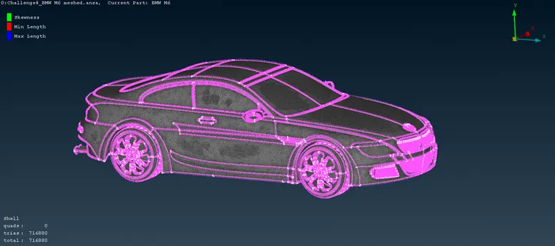
20. Now we will create the wind tunnel, i.e., fluid domain around the BMW car whose dimensions will be according to the parameters of the tunnel. The dimensions will be as follows-
- The front plane of the wind tunnel will be at a distance of 4 times the car length from the front of the car.
-The back plane will be at a distance of 6 times the car length.
-The top plane will be at a distance of 3 times the car length.
-The side plane will be at distance of the car length.
-The bottom plane can be taken at any distance with the only condition that it should not intersect with any part of the car.
Now, to create the tunnel we will make nodal points using relative option in points tab and give the required distance in accordance with the above criteria. All the points will be created in relative with one nodal point which we will make at the bottom center of the car.
Below image shows the nodal point at the bottom center of the car-
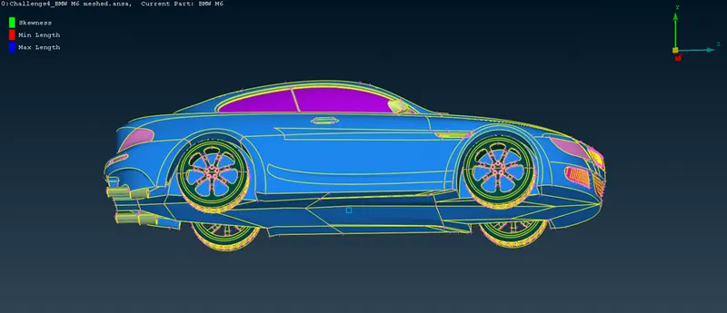
21. Now we will make different points at the front, bottom, back and top sides using the above point, which we will use to make the planes of the wind tunnel. Bottom image shows the different points on all sides-
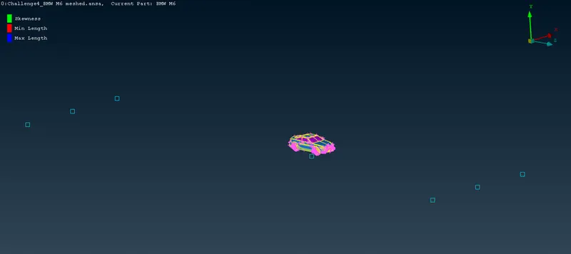
Now, using the points, we will create curves and then using the curves we will create faces. Below image shows the bottom plane created by using the curves-
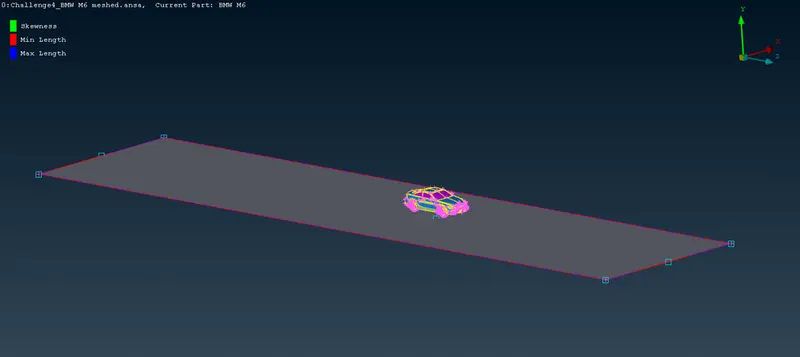
22. Now, we will make top plane by using offset tool and offsetting the bottom plane. Then we can create all the other sides using the new face tool. Below image shows all the sides of the wind tunnel-
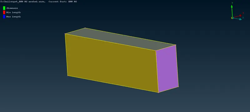
Now we will mesh all the sides of the wind tunnel by different mesh sizes. The element size for each planes are shown below-
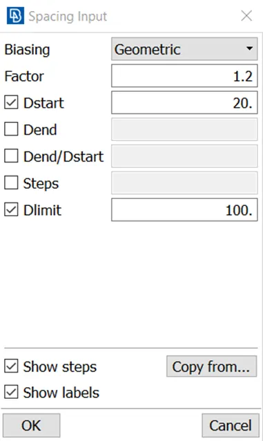
Bottom plane- 20mm
Top plane- 100mm
We will use manual spacing tool on the side planes by selecting the 4 side cons, which will mesh the side planes in an increasing or decreasing manner of element size. We will mesh the side planes in this way which will increase the mesh element size from 20 to 100 from bottom to top plane. The inputs in the manual spacing is shown below-
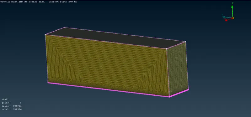
Below image shows the final image of wind tunnel after meshing-