Week 2 Challenge : Surface meshing on a Pressure valve
Objective- To mesh the surface of a pressure valve.
Introduction-
A relief valve or pressure relief valve (PRV) is a type of safety valve used to control or limit the pressure in a system; pressure might otherwise build up and create a process upset, instrument or equipment failure, or fire. The pressure is relieved by allowing the pressurized fluid to flow from an auxiliary passage out of the system.
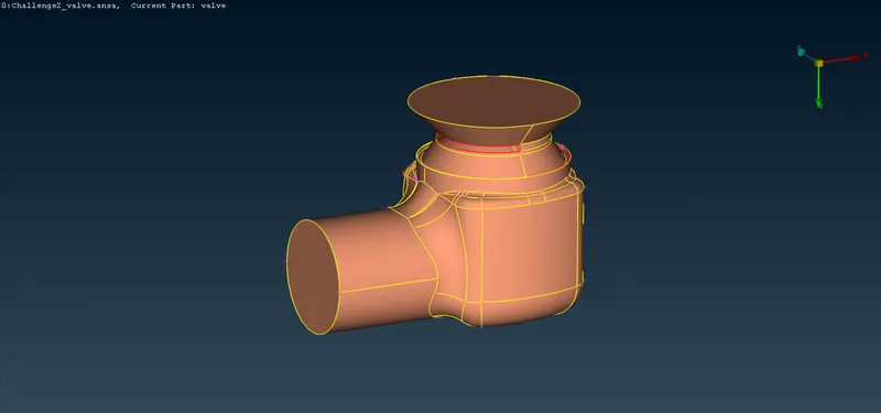
Here, we are meshing the surfaces of different parts of a pressure valve. It contains many errors as you can see in the below picture of the pressure valve. So, before meshing the pressure valve, we will have to rectify those errors.
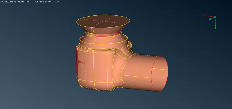
Image showing the errors of pressure valve
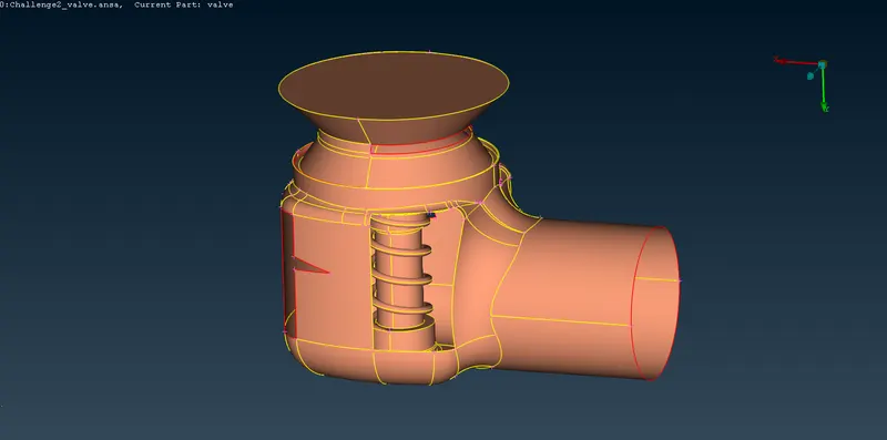
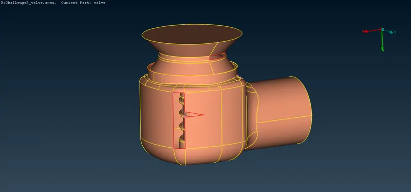
Image showing section view of the spring structure
Procedure-
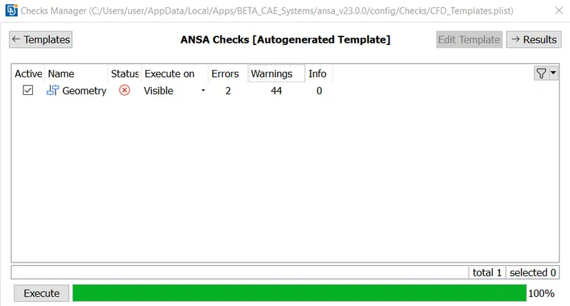
- First, we perform geometry checks on the pressure valve model. As you can see in the picture below of checks manager, the geometry contains 2 errors and 44 warnings which mostly warns about the single cons in the pressure valve model which are visible as red colour in the above image.
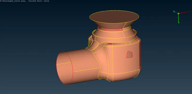
- For rectifying those errors and warnings we use different tools available in the ansa software. For simple holes we use 'fill hole' tool in the 'cons' tab which is shown in below example. Maximum holes in the first image below is filled with this tool at the same time as we can select multiple holes at the same time.
- For rectifying complex single cons, we use 'new' option in 'faces' tab which is used to add new faces using multiple algorithms like 'existing surf', 'planar', 'fitted' and 'coons'. In the below image we used coons tool for filling the hole -
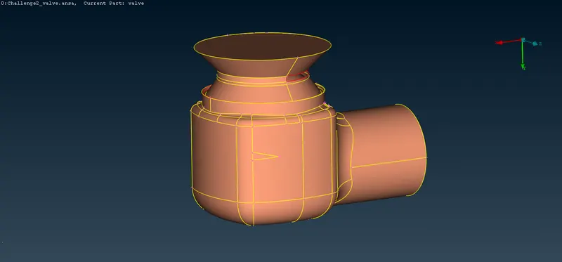
- We also cut some faces which are made during modelling, to make mesh generation easier and uniform. For this we use 'cut' option in the 'faces' tab.
- Below is the picture of the model with no errors after assigning new PIDs or property IDs to the surfaces-
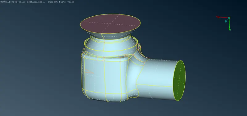
- For volumetric CFD simulation, we will need the model to be closed which is shown in the image above. So we make another surface at the bottom of the model, which in turn creates a triple con. The triple con is not an error since we need the surface for the test.
- Here, we have created multiple PIDs of different surfaces of the pressure vavle model to identify the different parts of the pressure vavle, which inturn makes our mesh generation process easy sometimes.
- In mesh generation, we have selected 3 cases for different element length, i.e., 1mm, 3mm and 5mm. In all mesh generation we have selected element type as 'tria'.
- For mesh generation, we specify the element type and maximum and minimum element length in 'mesh parameter' and then we specify the minimum and maximum element length in 'quality criteria' as shown below-
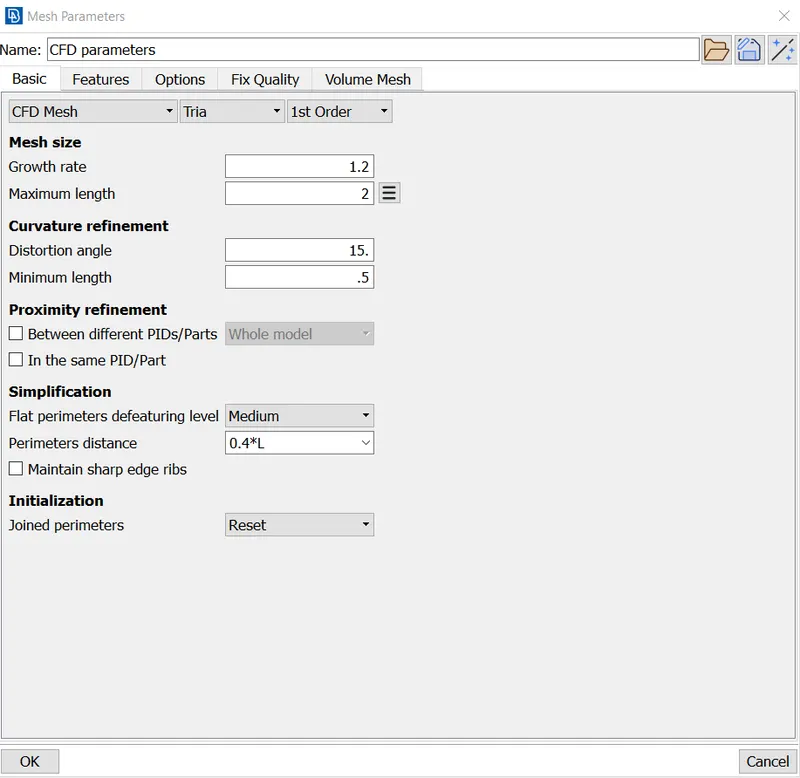
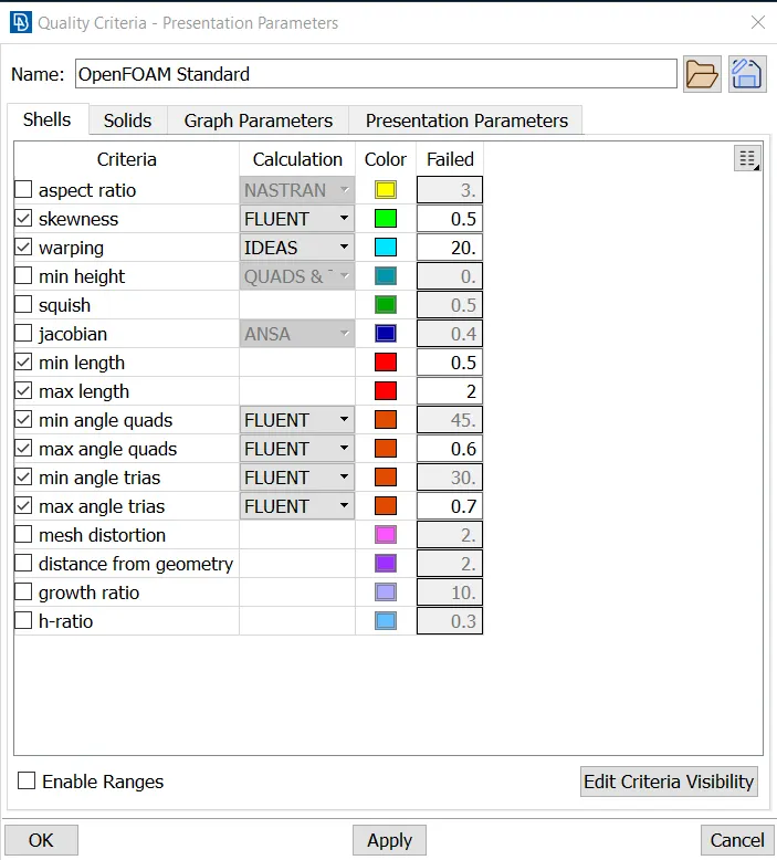
- Then, we select the length tool in perimeter bar to specify the element length of 'perimeter' and 'macros' by selecting the surface of the model which is to be meshed.
- The minimum and maximum element length should be in accordance with the chosen element length. For example, for 1mm element length we can choose minimum and maximum element length as 0.5mm and 2mm respectfully.
Result-
- Below is the picture of meshed pressure valve model with 1mm element length-
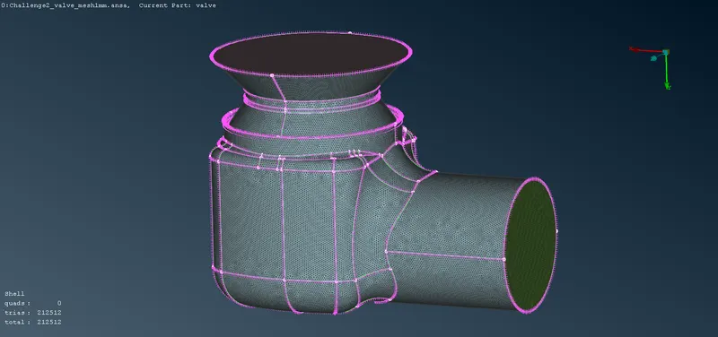
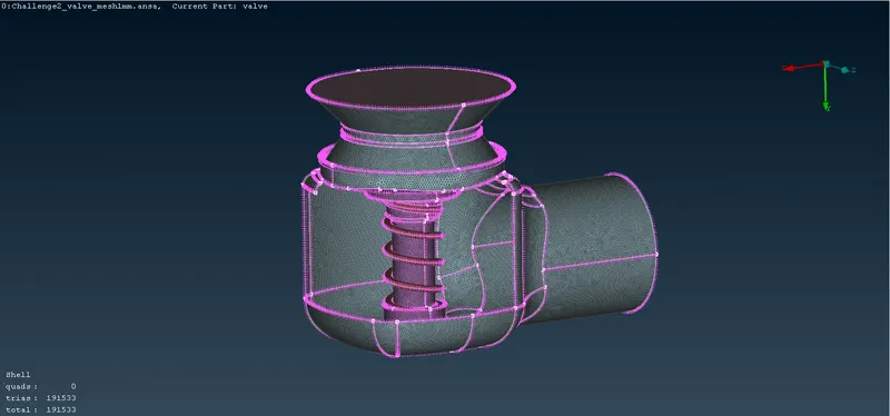
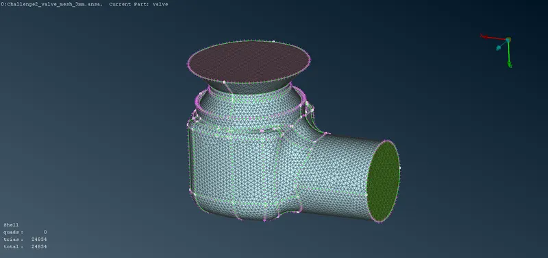
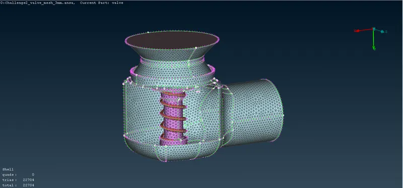
- Below is the picture of meshed pressure valve model with 3mm element length-
- Below is the picture of meshed pressure valve model with 5mm element length-
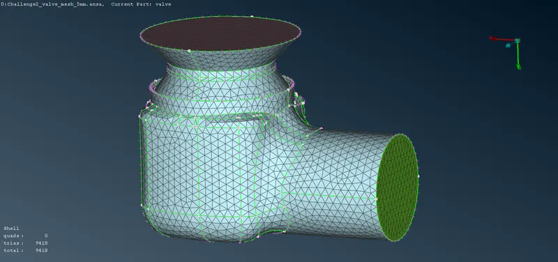
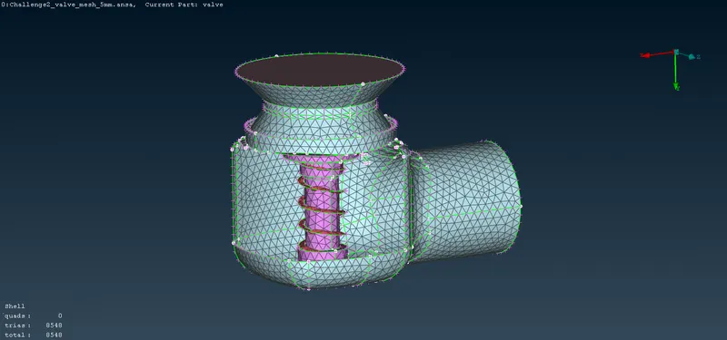
As you can see from the above figures, as the element size increases, the shape of the small parts gets distorted to accomodate the larger element like the above spring structure. So, we have to use different element size in accordance with the size or the application of the part or the focus region of the simulation.
You can also see the difference in the element density in the pictures above. The element density is greatest in the 1mm element length meshed model. Also, you can see the number of 'trias' element on left corner in each picture which is maximum for 1mm element length meshed model.
The meshing of the model with 1mm element length will give best and closest to accurate result since it defines the 3D model better by covering its physical form better. But the trade-off is that the higher the accuracy, the larger the simulations become and thus solve times are extended.
Conclusion-
The meshed pressure valve model with 1mm element length will give best result as compared to meshed model with 3mm or 5mm element length but it will inturn increase the simulation time.