Week 5 Challenge : Surface wrap on Automotive Assembly
Objective- To surface wrap on an automotive assembly which consists of engine, gearbox and transmission after geometric cleanup and merging of the individual parts.
Introduction-
The surface wrap tool wraps the geometry of interest to create a volume that does NOT have intersecting surfaces or non-manifold edges. The surface wrapper can be used when parts are overlapping, have duplicate surfaces or when your input has to high level of detail.
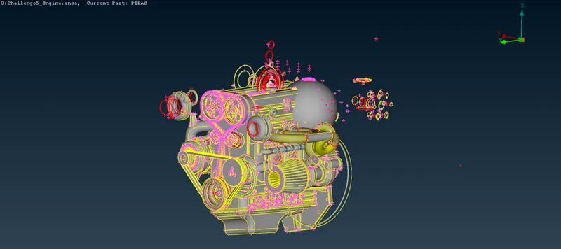
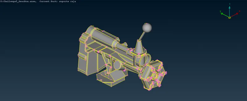
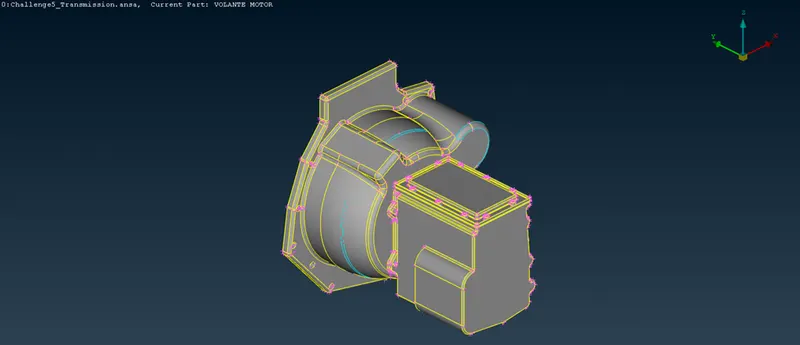
Below are the images of the engine, gearbox and transmission –
Procedure-
- For surface wrapping the whole assembly, we need to perform geometry cleanup on each parts of the assembly. But for surface wrap we don’t need to perform geometry cleanup inside and out of the parts, instead we only need to remove errors on the outside of the individual parts, i.e., we need to delete unnecessary faces outside the main assembly and we need to remove the triple cons which are visible from outside.
- So, as you can see in the image of the engine, there are lots of unnecessary faces outside the main engine. We can either delete the whole faces one by one or we can hide the main parts or faces of the engine and then directly delete the unnecessary faces.
So below image shows the engine after hiding the main parts or faces of the engine-
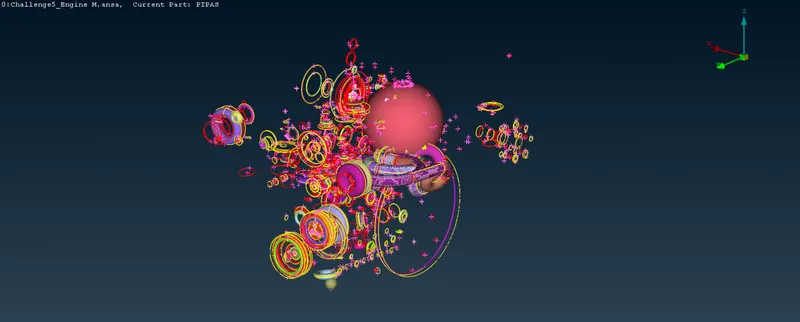
Now we will delete the unnecessary parts above until only main parts of the engine remains in the view. Below image shows the parts of the engine-
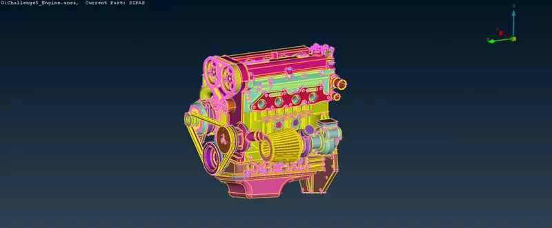
3. Now, we have to resolve the errors which are visible outside. There are many visible triple cons in the engine which we have to remove by deleting the extra faces. Below is one example of one part which is having a triple con-
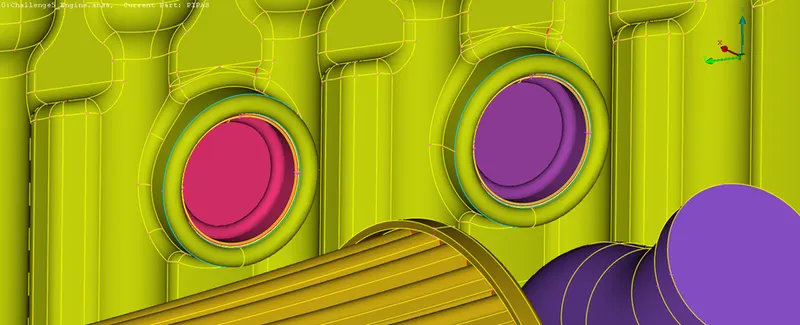
Here we will hide any surface where the triple cons are formed and delete the extra surface. Below image shows the parts after hiding the surface-
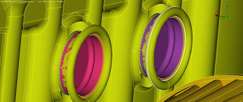
Here, you can see we have hidden the surface and the highlighted surface which we are going to delete to resolve the triple cons. Below image shows the final view of the part after removing the triple cons-
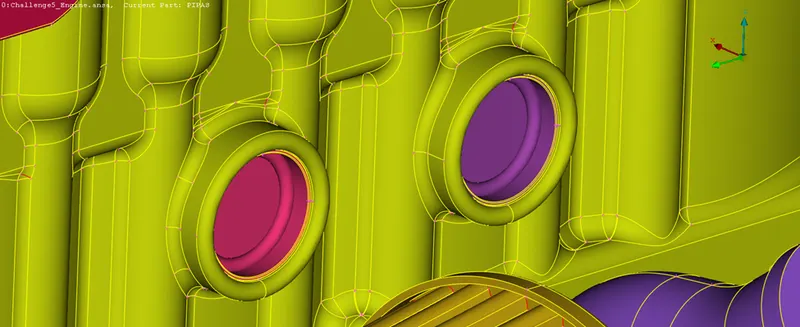
4. We will apply the same procedure for every triple cons which we are visible outside. Below is another example of triple cons in the engine-
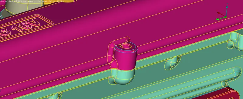
Below image shows the view of the part after hiding the face-
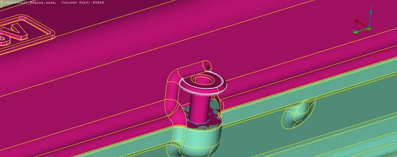
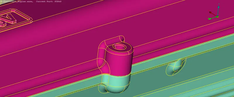
You can see the highlighted face which we will delete to resolve the triple cons. Below image shows the view of the part after resolving the triple cons-
5. Now after removing the triple cons, we will resolve the single con errors. One example is shown below-
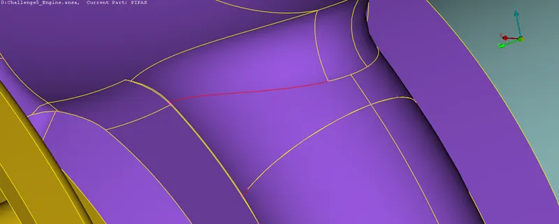
This single con was not resolving after using topo tool. So, we will delete the face connecting the single con which is shown below. There were also some needle faces which we will have to delete.
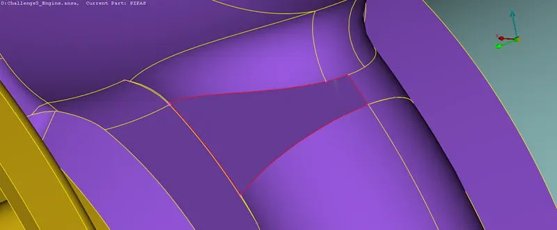
Now, we will make a new face by selecting every single con connecting the face which is shown below-
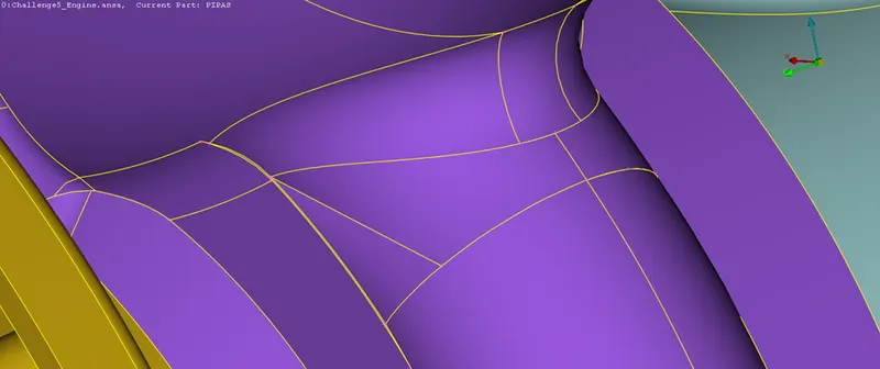
We will have to remove all the single cons using similar procedure.
6. Below image shows the belt drive in the engine for power transmission-
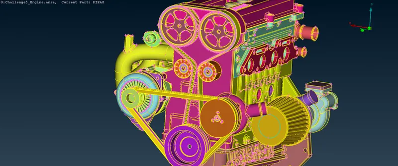
Since the belts are thin and contains too many faces thus we will have to delete them before surface wrapping. We are doing this because surface wrapping such small and thin faces will distort the surface wrap. Below image shows the view after deleting the belts-
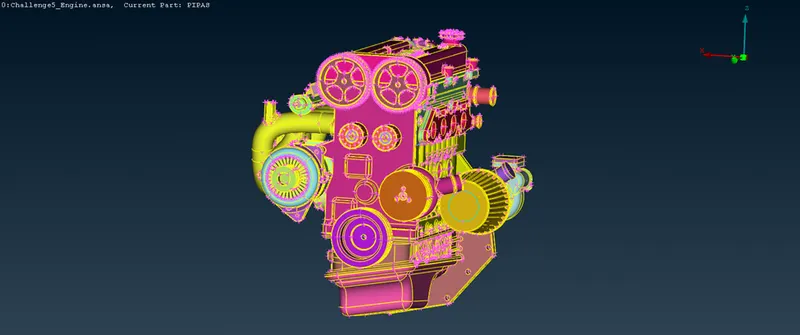
7. Now, before using surface wrap tool we will have to fill all the holes which are visible to us around the engine. That’s why we also don’t need to rectify the triple cons or single cons inside the engine. Below image shows an example for the holes in the engine-
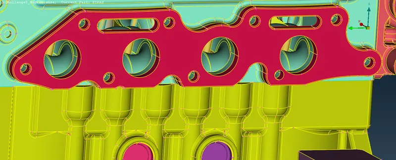
All these holes have to be filled before using surface wrap. Below image shows the view after filling the holes-
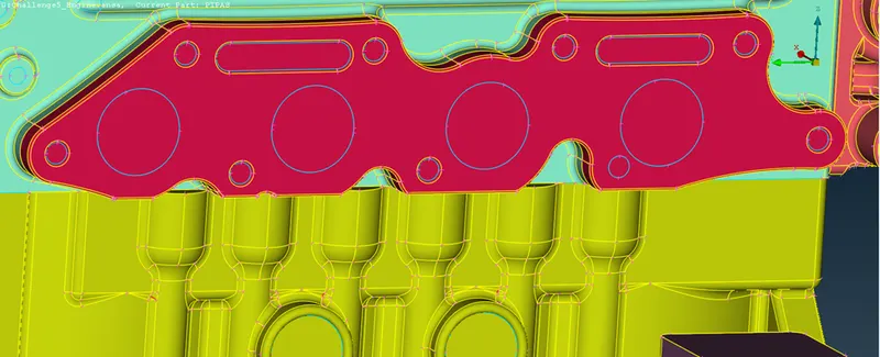
Similarly, we have to fill all the holes outside the engine.
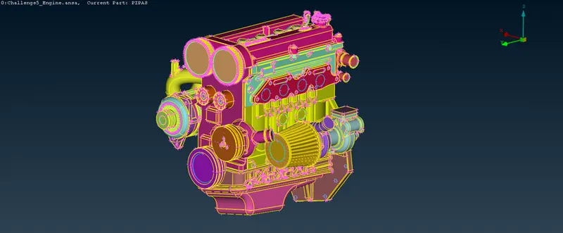
8. Below final image shows the engine after filling the holes and resolving the visible errors-
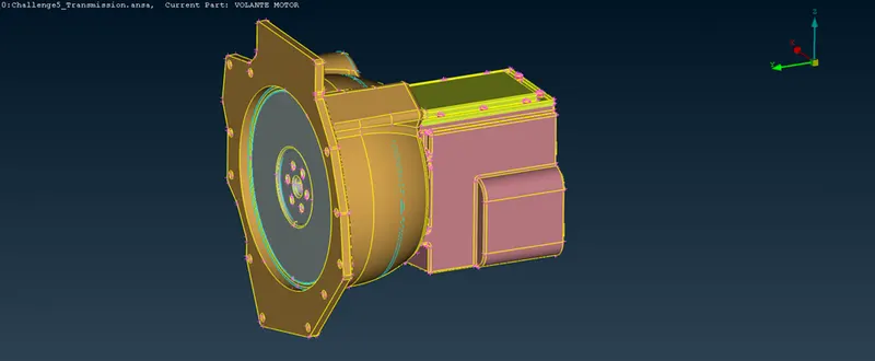
9. Now we will resolve the errors in the transmission in the similar way as we did in the engine. Below image shows the transmission-
Below image shows the triple cons in the transmission-
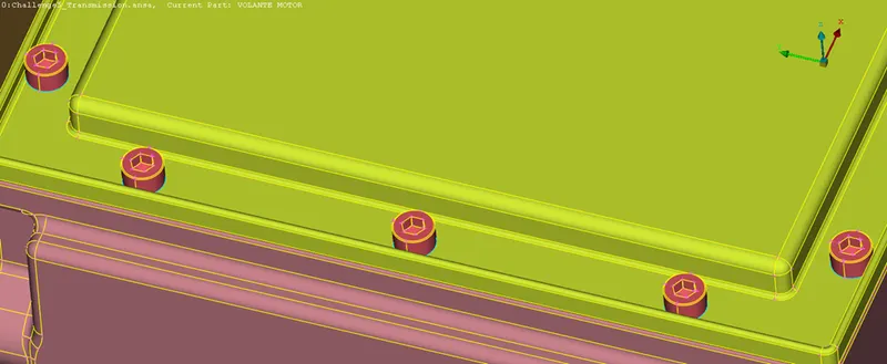
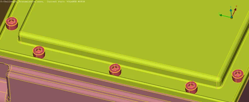
Now we will resolve it in the similar way as we did in the engine. We will hide face and delete the extra surface due to which the triple cons are forming. Below image shows the part after removing the triple cons from the part-
10. Below image shows transmission part which has triple cons at two places-
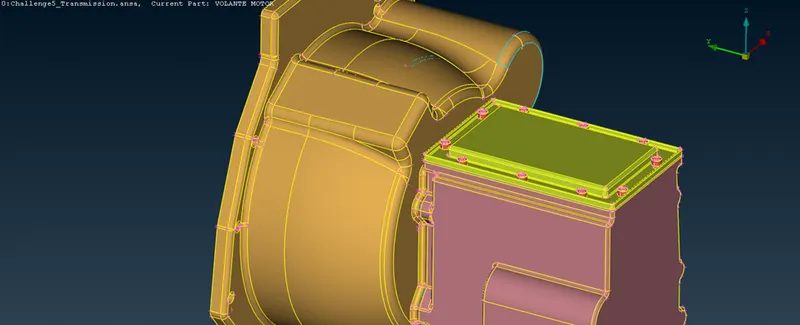
Now we will hide some faces to see the face responsible for the triple cons. Below image shows the view after hiding the faces-
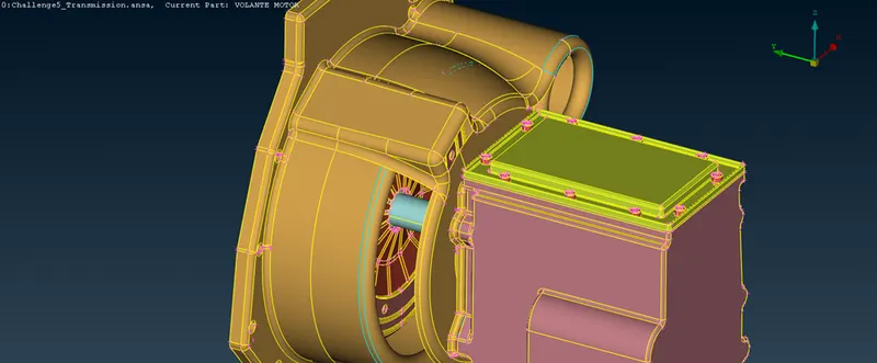
Now we will delete the necessary faces to remove the triple cons. Below image shows the view after deleting the triple cons-
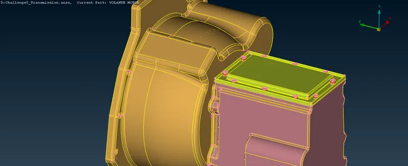
11. Below image shows the transmission part after resolving all the errors-
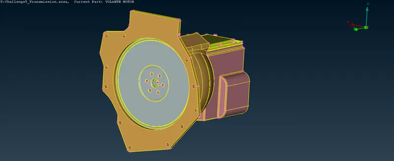
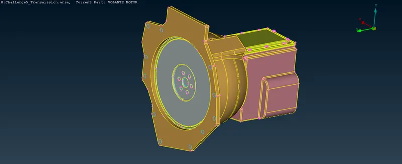
Now, we have to fill all the holes before using surface wrap tool for meshing. Below image shows the transmission after filling all the holes-
12. Now we will resolve the errors in the gear box in the similar way as we did in the engine. Below image shows the gear box-
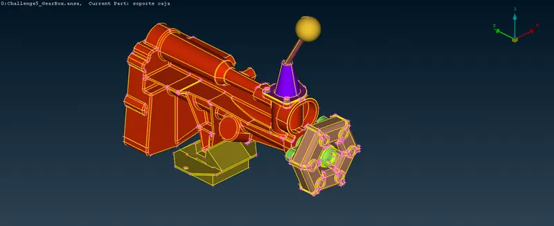
Below image shows some triple cons in the gear box-
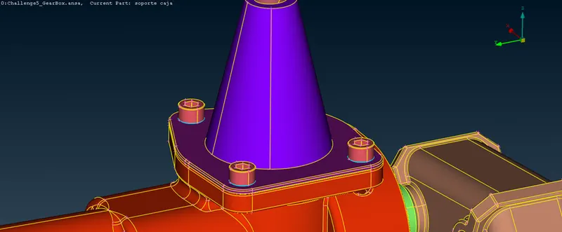
Now, we will hide some faces to see the face responsible for the triple cons. Below image shows the view after hiding faces-
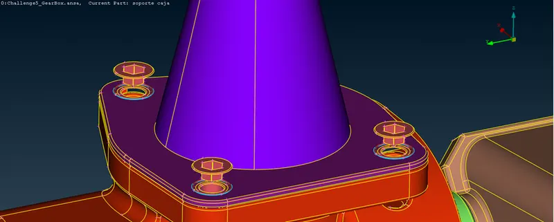
Now, we will the delete the necessary faces to remove the triple cons. Below image shows the view after removing the triple cons-
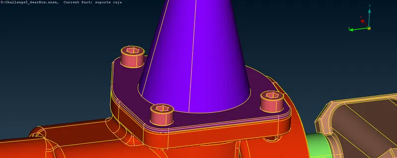
13. Now we will remove all the remaining visible errors in the gear box. Below image shows the gear box after resolving all the errors-
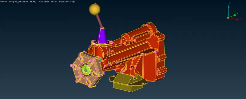
Now, we will fill all the holes before using surface wrap tool for meshing. Below image shows the gear box after filling all the visible holes-
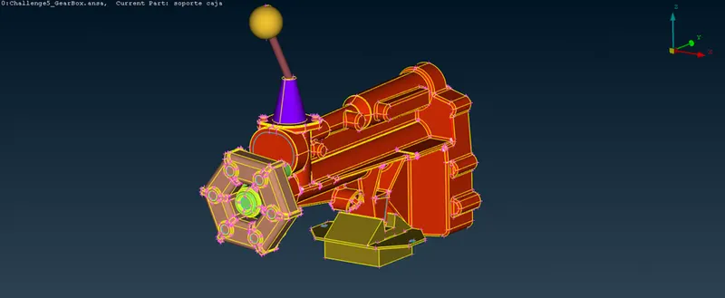
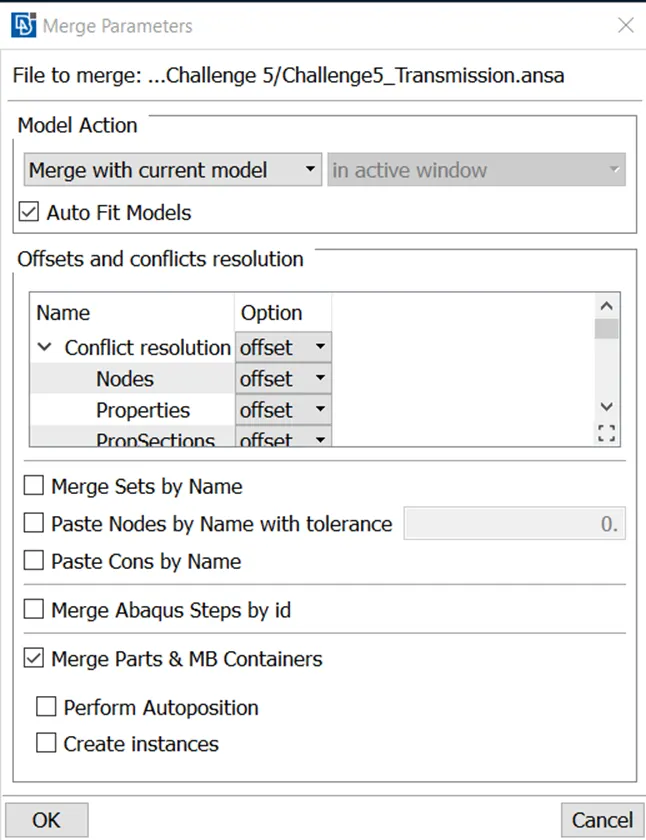
14. Now, we will merge the engine, transmission and gear box one by one in the engine file. So, for merging the transmission in the engine we will use merge tool under file in the toolbar.
Below image shows the merge parameters in which we have to always check the auto fit models option for merging automatically.
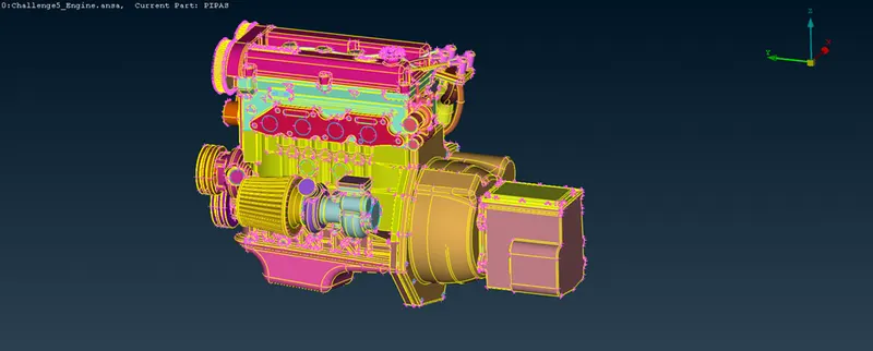
Below image shows the merged engine and transmission parts –
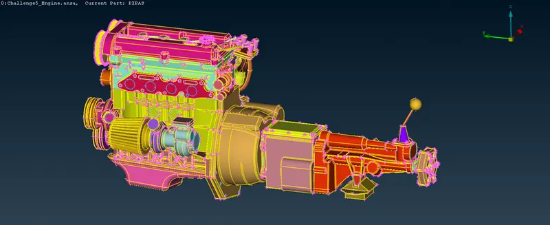
Similarly, we will merge the gear box in the engine. Below image shows the assembly of engine, transmission and gear box-
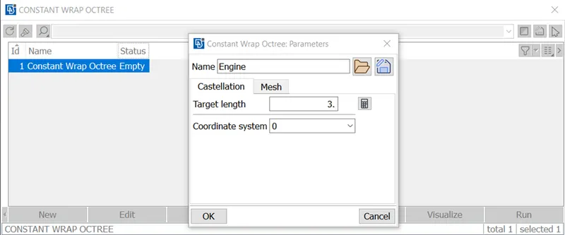
15. Now, we will surface wrap the assembly for meshing. We are taking target length for wrap as 3mm. The surface wrap tool is under the element bar as well as octree bar. Below image shows the window which shows the target length-
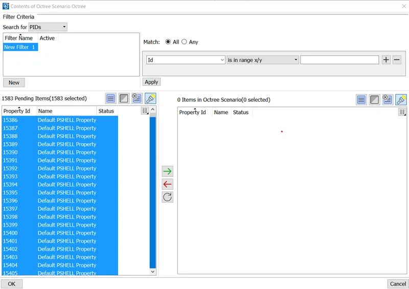
For content or part selection for wrap we have to select all the PIDs in the content window after double clicking the content option. After selecting all the PIDs we have to select the green arrow on the content window. Below image the content window and the selected PIDs-
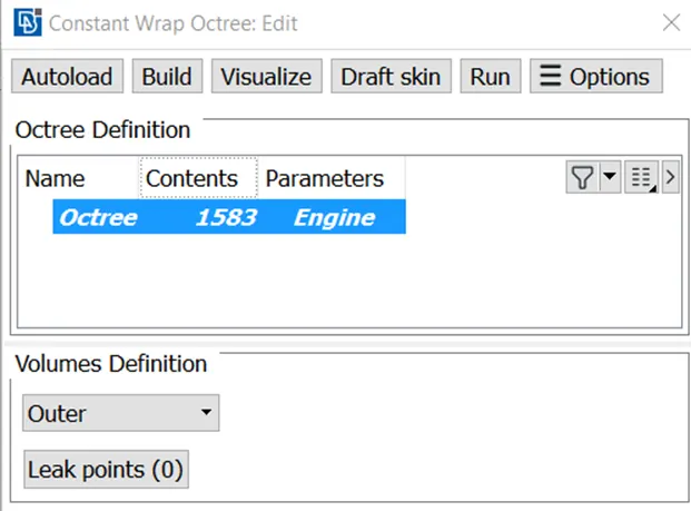
Then we have to select the run option in the below window for surface wrap which will start the meshing process-
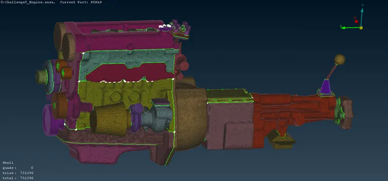
Result-
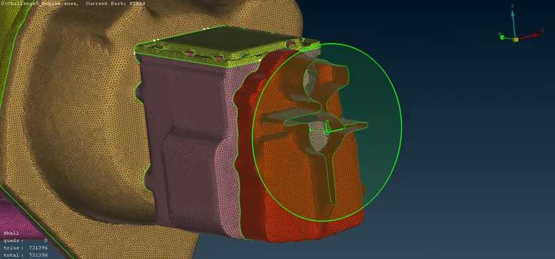
Below image shows the surface wrap of the assembly and cut section to show the inside meshing of the part-
Google drive link-
https://drive.google.com/file/d/1vIHS7vUWYm11EIvURHivkBfUJezAjInz/view?usp=sharing