Week 3:- BiW Fixture Design Methodologies Challenges
1.It is a technique normally involving with users as well as designers to be employed in creating a new technologies.
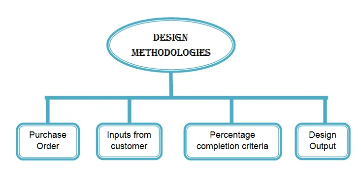
At the time of fixture design,the methodology divided into 4 subcatagories are define below.
Purchase Order(PO)
A purchase order is a contract between the buyer and the seller and it gives specific information like product or services to be delivered, delivery date, and any other terms and conditions including the price. The purchase order is also called as PO.
Below are details that usually forms part of purchase order:
- Products that are ordered
- Quantities i.e., (kg, meters, numbers etc.,)
- Price at which it is ordered
- Name of the vendor to whom the purchase order is being sent
- Shipment address or delivery location where the goods are required
- Billing address of the company
- Terms and conditions of payment.
- Due date of delivery/consignment.
Inputs from customer
Customers can tell you the exact product features they want and point you in the right direction. But at the end of the day, you’re in charge of designing solutions.Get to know your customers — not only what they want, but also what they can afford and what they’re willing to pay for.Designing a new product is not different, but to ensure that your output (final product) is appropriate (or epic), you must start by determining all of your inputs (design inputs) because they will guide & drive the design process.
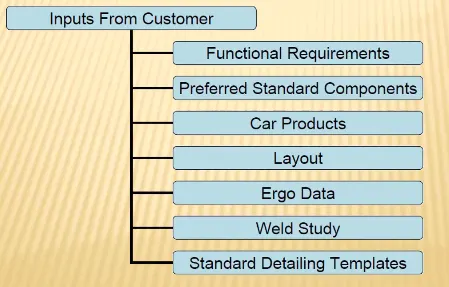
The customer inputs are like-
- Functional requirements.
- Standard components.
- Part dimensional stability(GD&T,Part list,CAD files etc.)
- Layout.
- Ergo Data.
- Standard Detailing templaets.
Percentage completion criteria
Percentage completion countdown start from PO/design start date to end of dispatch products.It helps to track or identifiy how much task is completion and how much go further for completing.
Concept design: 0-25%
Concept approval and simulation check: 25%-40%
Design freezing and Detailing: 40%-85%
Check and Final Dispatch: 85%-100%
Design outputs
The 2D drawings,3D files and Layout drawings are final outputs of a designer.
-Unitized tools: Multiple units of a common base,It required 2type of drawings
- Key sheet-An index of unit sheets and their placements on the tool base.
- Layout sheet-A detailed drawing of individual units to include all of child componets.
-Non unitized tools which can be completely detailed on layout sheet.
2. For design a fixture following inputs are requird from customers.
1.Functional requirments:
It is the basic requirements of a customers,weather it is being used for welding,Hemming,Gluing,Reviting etc.Depending on this functional requirments data design will start.
2.Preferred standard components:
At the time of design some standards as well as some standard components (Parts) are followed which is based on easy availability,cost saving as well as Time. The standards are ABB,NAAMS,ZYTRAN etc.
Standard parts like L-Blocks,Retainer etc.
3.Car Products:
GD&T: Called Geometrical Dimensioning and Tolerance of a part which fixture are design.It provides information about Clamps,Pins,Rest etc. as well as provide information of sequence and opening of clamps,Dumps and Slide stroke.
Part List:This is the list of parts are going to assemble the fixture.It includes part name,part number,tooling revision,part thickness etc.
Clamp Plan:The operations are perform by this clamping unit parts.It is the very important input from the customers.It provides loccation of the pins in fixture,Rests,Clamps,Dumps etc.We cant change with out permission of customers.
Product assembly process sheet: It provides detail of processs about completion of the parts from scartch to the final assembly products.
4.Layout:
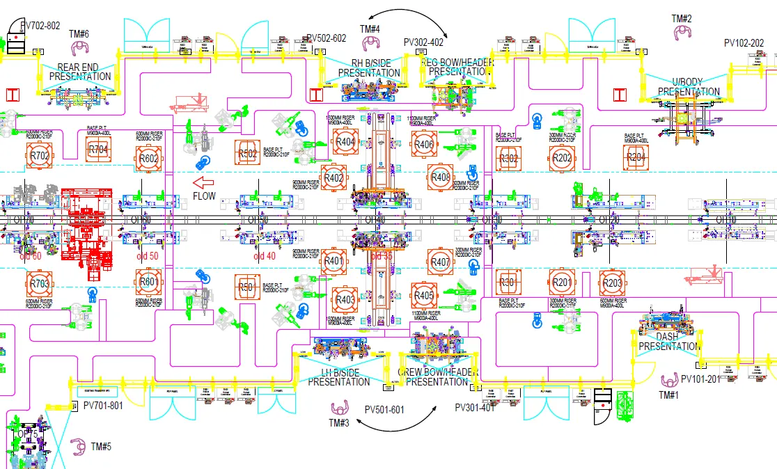
It provides information about flow of parts,station pitch,Robot stations,Tool changes,Subassembly links and loading/unloding sequences.
5.Ergo Data:
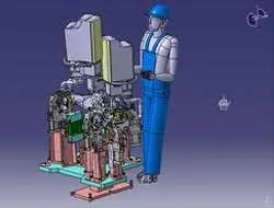
It is the study of human behaviour and movements during the assembly work.It provides loading height,working safety zone of the operator.It provides mainly comfortable use of machine by operator.
6.Weld study:
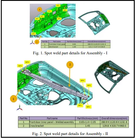
In this stage weld gun details are provided by customers.It includes the study of the weld gun used in operation depending on the size of parts,Thickness etc.The geo weld points help for geometry of the assembly and respot weld points are add extra strength to the already welded points.
7.Standard detailing templates:
The customers has their own standard drawing templates in which 2D drawing and detailed dimensions are provided by customers for detail study.
3.We get several inputs from customers in biw fixture design,Below following inputs we get from the car products.
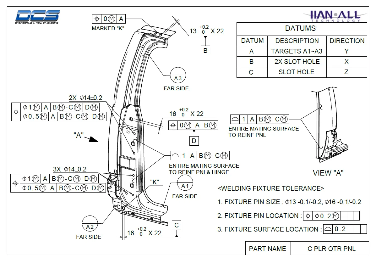
GD&T-Geometrical dimensioning and tolerance are given by the customer according to part functional requirments.It provides information about Clamps,Pins,Rest etc. as well as provide information of sequence and opening of clamps,Dumps and Slide stroke.
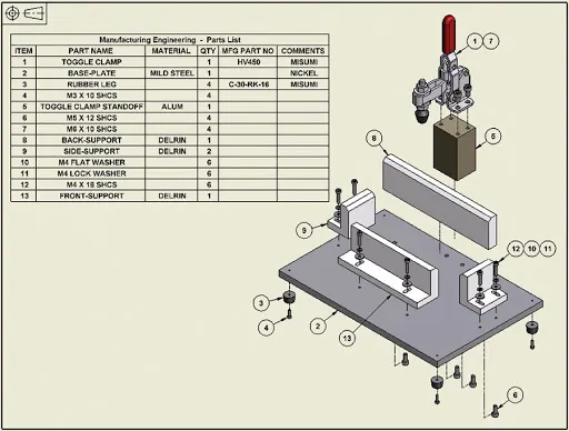
Part List-This is the list of parts which are assembled in fixture. Part Name,Number and Thickness etc. are listed in this drawing sheets.
Cad Files of Part-The 3D model file (.step,.iges etc) of the parts is given by customer from which fixture concept design are started by designer.Accepting as base model a designer start design fixture.
Clamp Plan-A clamp is a force actuating mechanism of a fixture.It hold parts securely by applying forces.Without customer permission we cannot change clamp plan.It provides location of the pins,rests,dumps etc.
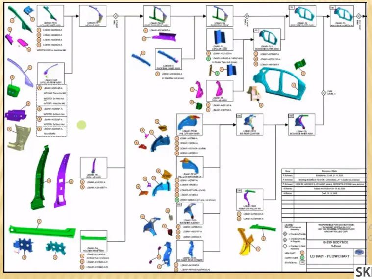
Product Assembly Process Sheet-These process sheets are provide detail process completion of the part from scratch to the finished product assembly.The no of assembly process and sequencial operations are define in this sheets.
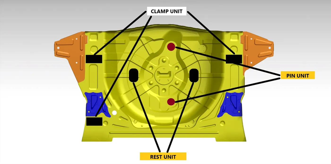
4.It is the important input from customers,It provides information about locating pins,Rest units,Dumps etc.Without any prior information from customer we cannot change it.To plan clamp unit below some customer inputs which we are consider at the time of design.
-No of sheet metal panels to be welded.
-Total no of spots.
- Welding gun details, if it is already recommended by process engineer study or details like shape and its type(C, X or Y).
-Study the PLP (Principle Location Points) data along with the nearby spot data.
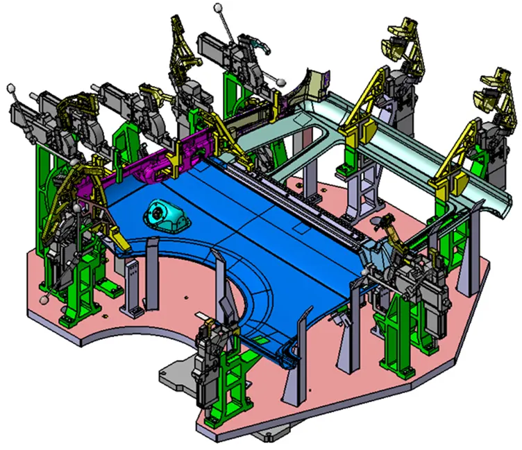
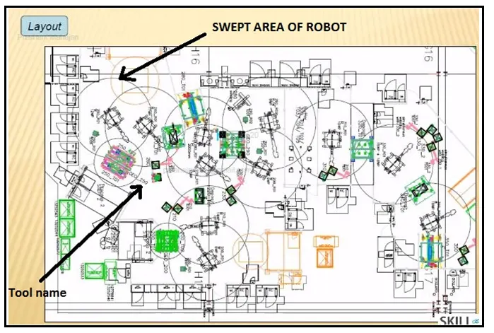
5.Lay out shows the blue print of thoughts or plans of a designer which is going to happen in real world.The aim of layout is both to present information in a logical, coherent way and to make the important elements stand out.
-It emphasizes all the facilities Man,Machine,Methode,Material etc, so that design plan achieved accordingly.
-In fixture design it shows all the objects of manufacturing as well as well execuation between Robots,Fixtures,Racks etc.It also shows the constraint of space available for fixture that we are design.
-Also it provides information about flow of parts,station pitch,Robot stations,Tool changers,Platform height,Sub assembly links and loading/unloading sequences.

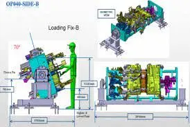
6.Ergo data provides inputs like Platform height, maximum & minimum reach from operator to fixture, maximum & minimum height of the fixture, wheather the child parts/ assemblies are visible while clamping or loading & unloading. Also provides informations like Loading height, working safety zone of operator, etc.
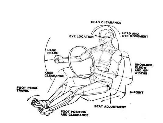
-For example,Following human factors should considered while designing automobile seat:
|
Measurement
(cm)
|
P5 | P50 | P95 |
| Standing | 156.3 | 167.5 | 178.7 |
| Sitting | 79.7 | 86 | 92.2 |
| Sitting eye ht | 68.6 | 74.8 | 80.6 |
| Weight | 45.7 | 63 | 85.4 |
Input&Concept Design:0-25%
The design inputs from the customers and after studying those inputs, the concept fixture designs are created.
Concept approval and Simulation check:25-40%
The concept design approval from the customers are given after study of simulation,Simulation plays important role in designing parts.
Design freezing and detailing:40-85%
After the simulation result,if there is no changes are required then the design is freezed.After that part detailing are started in 2D drawing.
Check and Final dispatch:85-100%
After detailing, the quality checking team start inspection of all the data and it will dispatch to the customer if everything is ok.
9.After releasing all the design data Outputs,this data will make reference data for acceptance criteria and ensure proper functional outputs of the device are identified.The design output data should proper documented,reviewed and approved before release.After approved by the HOD, the date and signature of all individual responsible persons also documented which is approving the ouputs.
Design and development outputs considered as follows.
-Meet the input requirements for design and development.
-Provide appropriate information for purchasing,production and for service provision.
-Contain reference product acceptence criteria.
-Specify the characteristics of the product.
A design ouput is a drawing or specification of parts or standards or manufacturing instructions or assembly and subassembly of products.The output consists of 3D models,2D drawings which provides detail of parts,BOM and other related documents.There are some tools which are multiple units on common base are called unitized tools ex. fixture which includes no.of units on the same base,they are required 2types of drawing sheets as follows.
- Key sheet-It shows the index of the unit and their placement on tool base.
- Layout sheet- It is the detailed drawing of individual unit to include all their components.
Non unitized tools which can be completely detailed on layout sheet.
-The output should compile with following points
- Approved standard parts should be used wherever possible.
- Design should be as simple and economical as possible.
- Design must comply with all safty and economic standard.
- Design must provide for controlled and damage free handling off product.
- Adequate error proofing provision must be encorporated in each design by providing proximity switches,Rough locators etc.
- The weight of moving parts must be kept in minimum while mataining max. strength.
- Frames and structures are followed simple design.
- Design clearance and accesibility for routine maintance and services.
- Motion control must be considered on any moving parts.
- Design is responsible to validate all clamps and weld guns.
10.Structuring a design tree implies to a process where all the assemblies and parts are named in a specific standard.Different customers have their different standards to structure a design tree.
-It is an important process which helps us to identifiy a specific part or assembly as to which project,tool or unit it belongs to.
-This helps us to avoide to errors during design study,manufacturing and assembly.
-If the parts or assemblies are not properly or the design tree is not structured properly, it will create confusion to understand the design and may create major possibilities of making error.
-Naming of a fixture or a unit or a part gives the information as to which project or zone or assembly do they belong.
-It can help us to identify the quantity of items of same type or different types are being used in assemblies.
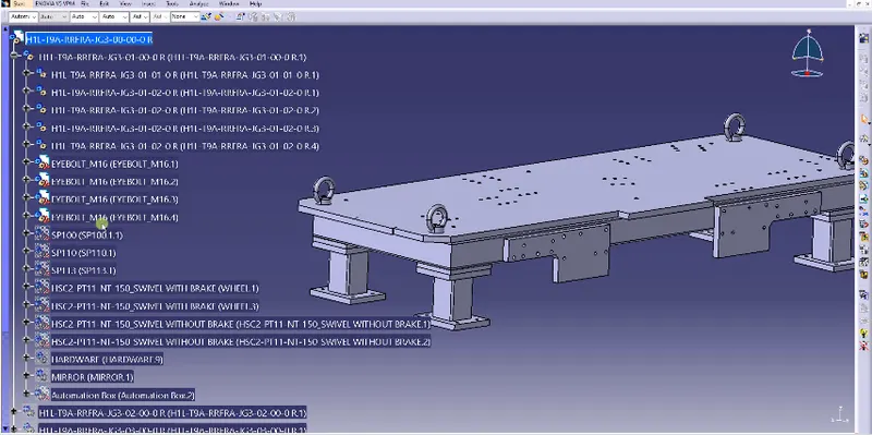
-In above figure it shows that the design tree in which designed parts or manufacturing parts are top and all standard parts are in bottom.
-The blue highlighted number is H1L-T9A-RRFRA-JG3-00-00-0R.It can be identified as follows.
H1L-T9A: Project name.
RRFRA: Panel name
JG3: Jig no-3
00: Unit no.
00: Part no.
0R:Component no.
-Under the product there are main assemblies,sub assemblies,child part,standard parts etc.to identify all parts are provided with specific no,zones etc.
11.Designing a unit of fixture is often a complex process, considering the variations in coordinate systems and basic rules such as maintaining few elements in specific orientations,all are assemble together form different units of fixture.
-Different different units have different purpose of functions.Like resting the panel,clamping the part,locating the part etc.There are 2types of units simple and complex unit.
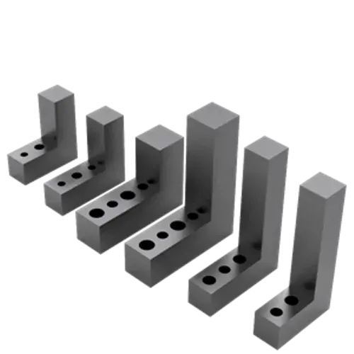
-Simple unit consists of Rest unit,Fixed pin unit,Re tract pin unit,Sensor unit,Base unit etc.
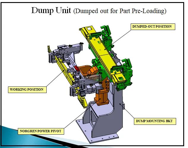
-Complex unit consists of Slide unit,Dump unit etc.
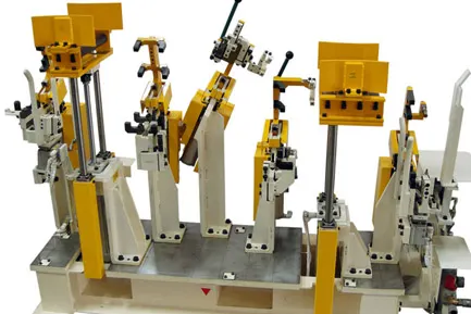
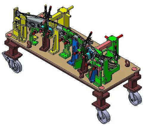
-Following are the typical types of units used in BIW Fixture design.
- Fixed pin unit-It is a non movable locating unit used for proper location of the part.
- Retract pin unnit-It is movable locating unit.
- Rough locator unit- It roughly guides the operator for locating the part.
- Rest unit- The panel is rest on this unit.
- Base unit-It is the unit on which all other units are mounted.
12.It is a unit designed to locate car panel using pins.
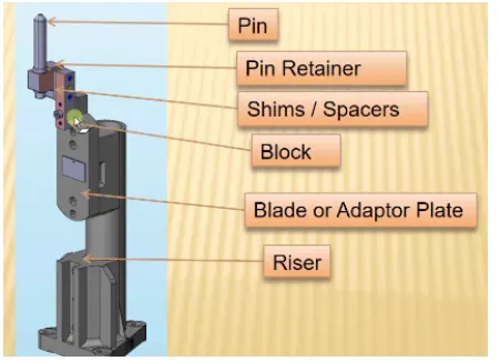
-Pin,pin retainer,shims,blocks,blade and riser are the part of fixed pin units.
-The body part is constraints by a set of appropriately locating pin,so the total constraint of the locating pin should constraints to prevent any movement.
-Pin retainer used to hold pin firmly.
-Shims are the small part which comes within the thickness 0.1,0.2,0.5mm etc.In fixed pin shims are used to adjust translational motions.Shims also play important role to adjust holding and locating tolerances.
-Riser is the standard part which is used to rise up the height of whole unit.Blade or plates are mounted on the riser.Other parts like cylinder,arms etc are mounted on the blade.
Purpose:
-Car panel are locate using pin.
-The fixed pin unit is the partt of the 3-2-1 principle.It restricts 6 degrees of freedom of the car panel.
-It is necessary to have 2pins to locate car panel.One pin must arrest 4ways(4 translational) and other must arrest 2ways (2 rotational) of a car panel.
13. Fixed pin unit consists of Pin,pin retainer,shims,blocks,blade and riser are the described below.
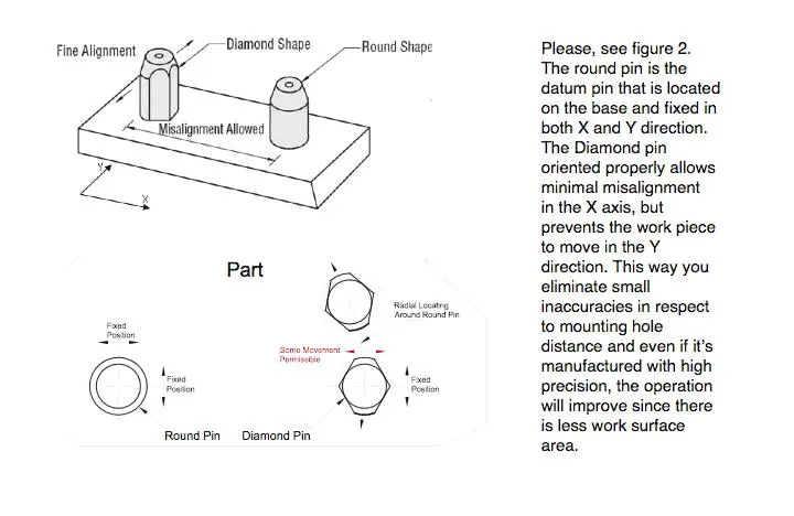
PIN: Pins are used to controlled fine tolerance position of work piece.Generally 2types of pins are used Round pin and Diamond pin.
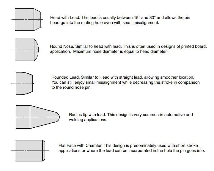
There are several styles of pin Head shapes used to locate car panel.They serve differrent purposes and can be utilized in a varriety of applications.
PIN RETAINER: It will support or hold firmly the pin.
SHIMS: Shims are the small parts comes with thickness of 0.1,0.2,0.5mm etc. and plays vital role for all adjusments.For example-
For compensate the stackup tolerance that reflects at the panel holding part myler,due to this tolerance myler goes up or down from its define position.So it will make impression or dent as well as weding distorsion on the panel.To adjust the myler we use shims so the panel won't deformed as well as not leave any dent and impression mark.
BLOCKS: To hold pin retainer and adjustable shims we use blocks.It is used just to connect one part another
BLADES: These are plates mounted on the riser to the clamp cylinder.These plates make important role to build the units.Plate design required as compact as possible.
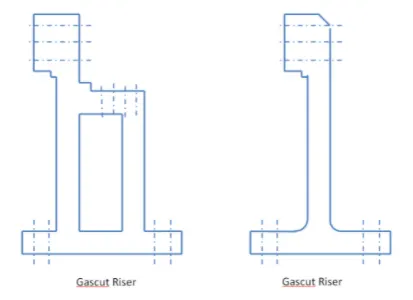
RISER: Riser is the standard part which is used to rise up the height of the whole unit.
14.The rest unit is design to rest/support car panels by using NC blocks/myler/Fingers.
-Due to less parts of design and only purpose of supporting/resting car panel it is a simplest methode.
-Because of this simplicity the rest unit is combine with all other unit to reduce cost of overal project.
-It can be combine with clamp unit to clamp as well as rest the car panel.It can be combined with locating unit to locate as well as to rest the car panel.Also locating,clamping and rest unit can be combine together in one unit to reduce cost.
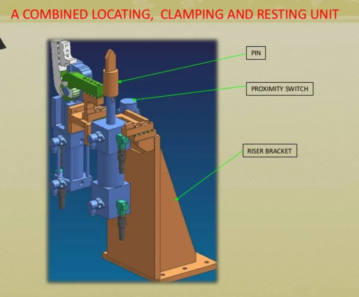
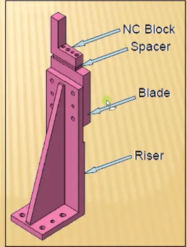
It consists of following parts:
Riser:It is a standard part used to rise height of unit. Riser is a structure generally used to mount the toggle clamp,clamp mylars and location pin.It is not necessary to have one riser where all the parts of clamp or rest or location units are mounted.
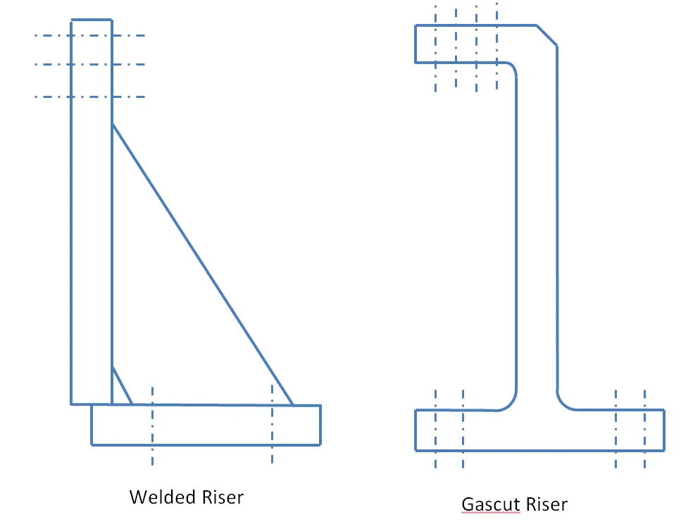
Blades: These are plates mounted on the riser to the clamp cylinder.These plates make important role to build the units.Plate design required as compact as possible.
Shims: Shims are the small parts comes with thickness of 0.1,0.2,0.5mm etc. and plays vital role for all adjusments.Shims are typically used in order to support, adjust for better fit, or provide a level surface. Shims may also be used as spacers to fill gaps between parts subject to wear.
-It is used one in direction in rest unit which is up and down because it requireds adjustable height only.
NC blocks/Myler/Fingers: Mylers is the components which holds the panel while operation are perform.MYLAR is one kind of block that touches the panel and holds or clamps the panel. Mylars are always designed in CAR LINE. Mylar is also called NC(Numerically Controlled)Block. Mylars are mounted on any block or plate with Shimming, So that height of mylar can be adjusted accordingly at the assembly level.
-The top side myler is called clamping myler and bottom side myler called resting myler.It doesnot allow deformation of part due to welding stresses.
15.Sensor is a device which detects or measures a physcical properties and records,indicates or otherwise response it.
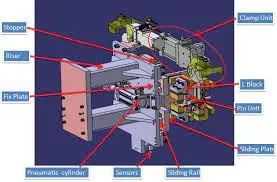
-A unit is designed to sense car panel using electrical sensor called sensor unit.It sense and provide signal to PLC for execute next process.
-The sensor is very sensitive and easily damagable,so a sensor cover is provided for a safety purpose.
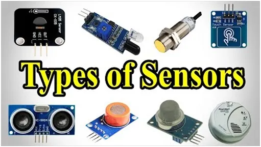
There are different types of sensors as follows-
- Proximity sensor
- Laser sensor
- Photoelectric sensor
- Infrared sensor etc.
Fundamentals of sensor unit design:
-The assembly of a car panel consists of no of panels.The location of each and every panel is fixed.There are some locating units,clamp units,rest units are provided for proper location and operation.The sensor is attached in this unit to sense the part is loaded or not.If the part is not loaded it will remains neutral not sense any part ,so operation will not start and viceversa.
-If the part is big in size there will be 2sensor required to guide the part,because the part will load correct position in one end and will be not positioned in other end due to which assembly part not ok and rejected by Quality Dept.So to avoide these kind of situations the part should sense by 1 or 2 sensor depending upon there sizes for proper part assembly.
-Sensor can be adjusted to the perticular distance from the panel by using 3-directional adjustable way.Proximity sensor have range 5-10mm distance to sense the part,if we go for lasor sensor the range distance increases.So sensor unit required design in such a way that it will adjust min. 3-directional way to avoid any collision or any other accidents or damages.
16.A rough locator is a part designed to locate the car panel with pins and guide the operator.It can be a standard part or make part.It is a device to establish and maintain position of a part in a jig or fixture.
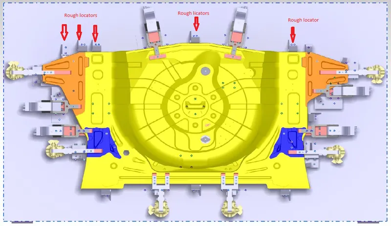
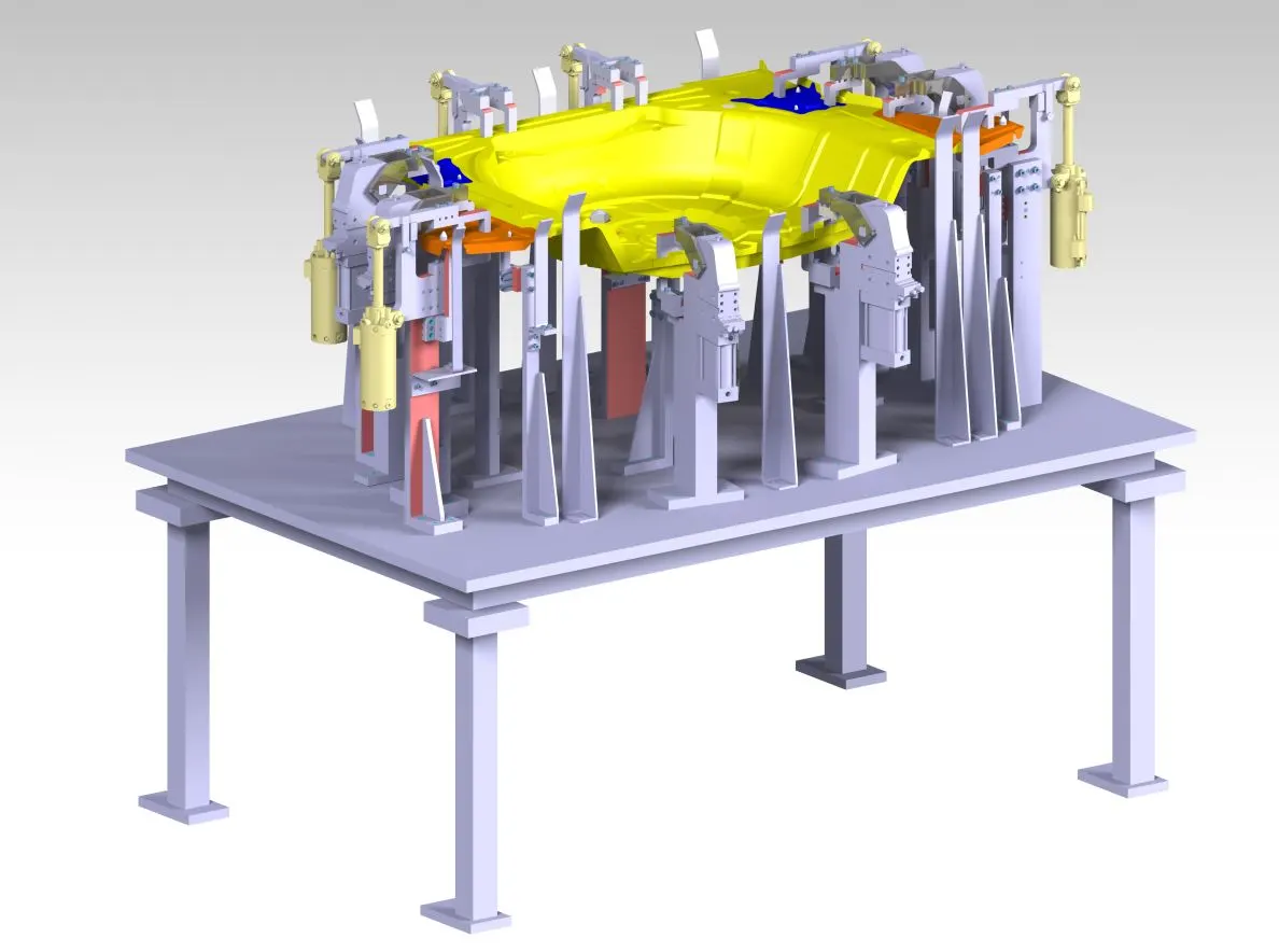
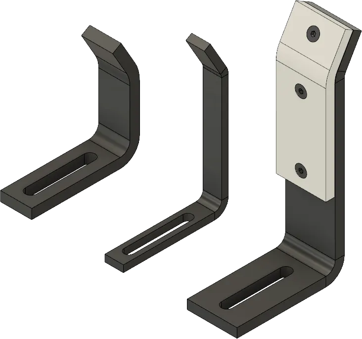
-It is also called full proofing method,because without rough loccator part cannot be lodaded in correct position.
Fundamentals of rough locator design:
- Rough locator should be placed at the edges of car panel which it has to guide.
- Rough locator has to be placed in same angle of the car part edges with a min.distance 2-5mm from the edge of car parts.
- Rough locator should guide the panel in pin arresting direction.
- Rough locator should start guding the panel before 10-15mm to the start of the pin engagement.
- Rough locator should be designed with entry angle 30-45 degree for the car panel.
- Rough locator should be designed with 2slots to mount the easy adjustments.
- The slot should be in direction of car part guiding.
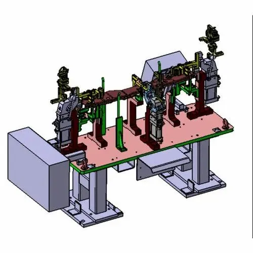
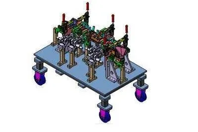
17. A base unit is a unit design to mount all the other units (clamp unit,Pin unit,rest unit etc.) of the tool,also other parts necessary for a tool like penumatic valve box,trunk cable path will also be mount on to a base unit.
-It is the fundamental component of the fixture.The base unit design is different according to the panel,design of clamp system,location system etc. for example-
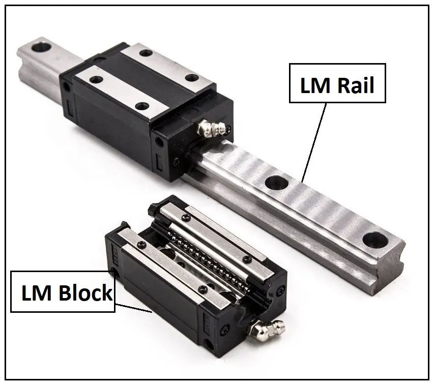
- LM guide ways are preffered over hardened guide ways due to least co-efficent of friction.
- Reverse stroke of 10mm to be considered in both forward and retracted condition.
- Cylinder and LM guides to be validated for load and stroke.
- LM guide raillength should be standard and should be more than the actual stroke.
- Mechanical hard stop to be considered for both extended and retracted condition.
- Shock absorber to be used for both extended and retracted condition to reduce impact load.
- The two end limits to be sensed externally by a proximity sensor.
- The shoch absorber should be mounted such that it is perpendicular to the pivot,at mid stroke or +/-5 degree.
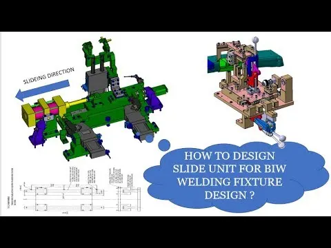
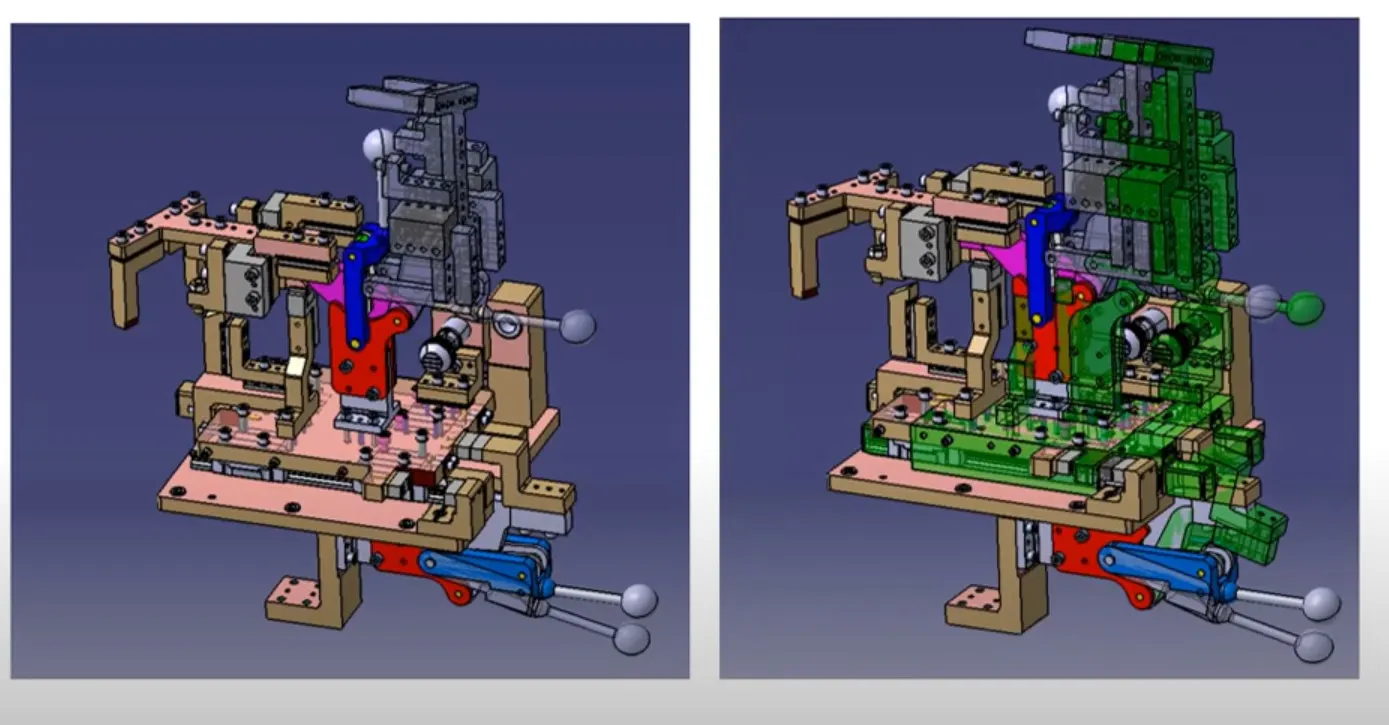
-Slide units are used when we have some space constraints.So we dont have space to design different special units and to assemble it.In those cases we use sliding units.