Week 8:- 3D Finishing - Challenges 1
A.NO:-1
-It is the stages where 3D design being completely finish in 3D Software and ready for final simulation,show off and 2D purpose.
-While finishing the design the nominality of is checked which ensure easy assembility of units.
-The hole concentricity and hole sizes are checked to ensure the easy assembly of different parts.
-The gaps between the different units are checked to ensure the proper individual working of different units.
-Fastners are implemented as per the hole size and standard color codes as per the customer requirment are applied to the differentiate types of holes wheather it is simple hole,threaded hole or counter bore hole.
-Renaming the assemblies and parts are done to give every part a different identity in which assembly of each part is going to be fit.
-After doing all these things the model is going for simulation and 2D Detailing.
A.NO:-2
Below points are taken consideration while finishing the design are-
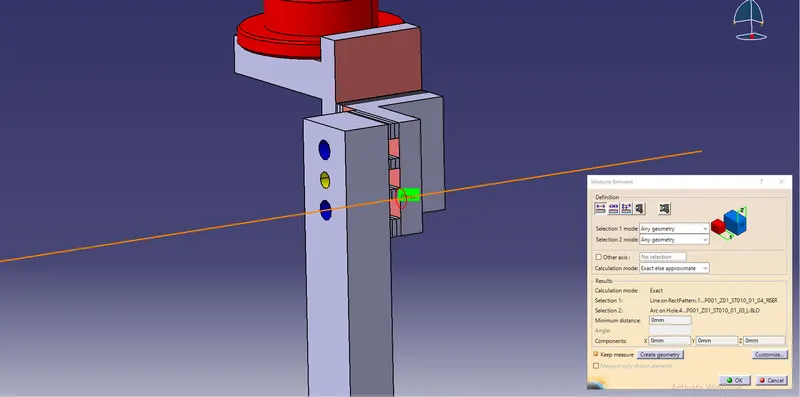
HOLE CONCENTRICITY AND HOLE SIZE.
Hole concentricity and hole sizes are checked for easy assembly and 2D detailing of all the parts.
COLORING STANDARD.
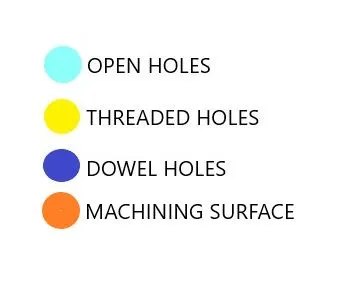
In 3D finish hole coloring is done because it helps to identify what type of hole it is?It depends on customer standard .Customer specifie color like
-Dowel hole should colored Blue.
-Threaded hole should colored like Yelow.
-Simple hole should colored like Cyan blue.
-For machining surface area should colored like Orange.
MACHINING AREA
The machining area of every part should be define and the machining area should be highlited with standard color code.Machining is properly done on parts to proper mount of mating parts.Machining only on desire faces reduce cost and save time and also increase accuracy of dimension stability,so that going before simulation or detailing maching area should be define.
NOMINALITY
All units dimension should be maintain nominal to facillate easy assembly of the unit.
PNEUMATIC LAYOUT
The collection of all the pneumatic pipes which works as a inlet to the pneumatic cylinder and arrange inorder is called pneumatic layouting.For working function it should be arrange properly for proper unit .
GAPS CHECKING
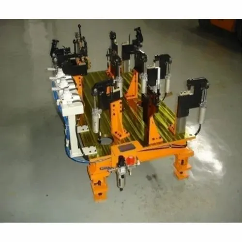
The gapsbetween the difference units checked to ensure the proper individual working of difference units.
FASTNER IMPLEMENTATION
Fastner should implemented all the units as per the requirment and load on the part.
AVOIDING CLASH BETWEEN DIFFERENCE PARTS
Proper gap should be maintained between units to avoid clash.
MYLAR SPLITTING AS PER PANEL PROFILE
Mylar splitting as per panel profile should check and conformed while finishing the design.
A.NO:-3
-Rough locators are usually used in loading and unloading of perticular parts.
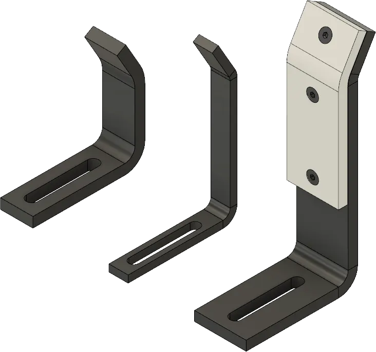
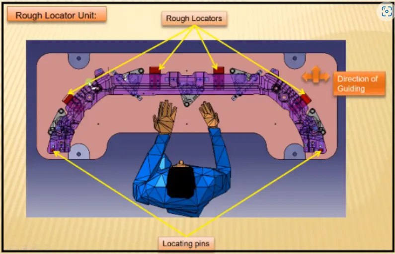
-Rough locator unit is a part design to guide the operator to locate the car panel on the pins accordingly.They have slot for adjustment.
-Rough locaters are used to help locate workpieces in the automation process.Locating refers to the desire location where you want the workpiece to be,when it is getting worked on either by person,team or robot.The accuraccy of the locating components directly affect the consistancy and how final product will come out.
-A rough locator can be standard part or make one.It is also work as poka-yoka.
-It can be called as full proofing method because due to the rough locator the part cannot be loaded in correct position.The rough locators are set accordingly in angle of respectively panel hence part can be loaded define direction and orientation.
A.NO:-4
-Rough locators should be placed at the edages of car panel,which it has to guide using locating pins one can easily restrict movement of entire car panel.
-Rough locators has to be placed in the same angle of car panel part edage with minimum distance of 2.5mm from the edage of car part,so it should not damage car panel.
-Rough locators should guide the panel before 10-15mm to the start of the pin engagement.
-Rough locators should be designed with entry angle of the car panel,generally its range between 30-45 degree.
-Rough locators should guide the car panel in pin arresting direction generally.
- Rough locators should be designed with 2slots to mount for easy adjustment.
-The slot should be in direction of car panel guiding.
A.NO:-5
-Welding is predominantly used in automobile industries and requirments for the fixtures that ease the welding process is a contineous developing task in any industries.
-Car Body-in -White(BIW) is a complicated steel structure including 300-500sheets with complex shape and are assembled by means of welding in a high rhythm through 55-75 workstations.
-The foremost step taken before starting the design of welding fixture is to arrive at the spot welding welding locations,
-The location and orientation of other critical units of the fixture including clamps,locators etc. are decided based on the weld spot distribution.
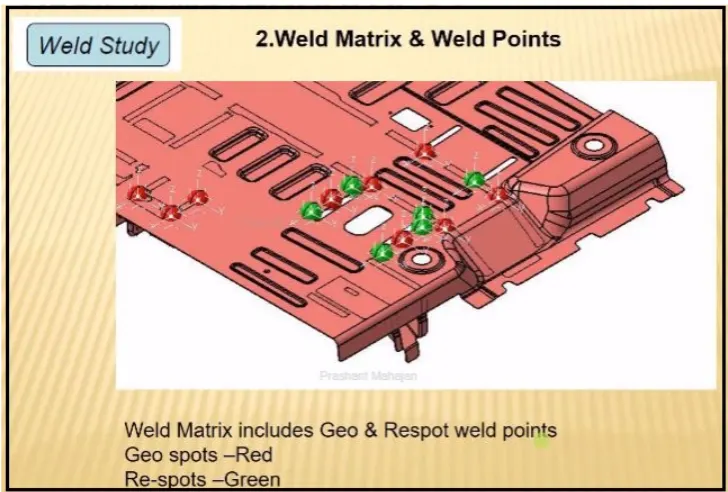
-It includes information of weld gun details,weld matrix and weld points.There are 2types of welding points geo weld point and re-spot weld points.
-Geo weld points defines the geometry of part and re-spot do all other remaining weld points also add strength to geo weld points.The spots can be geo spots or re-spots shown in figure.
-
Different types of weld gus are shown in figure below-
Below figure shows weld gun study over panel-
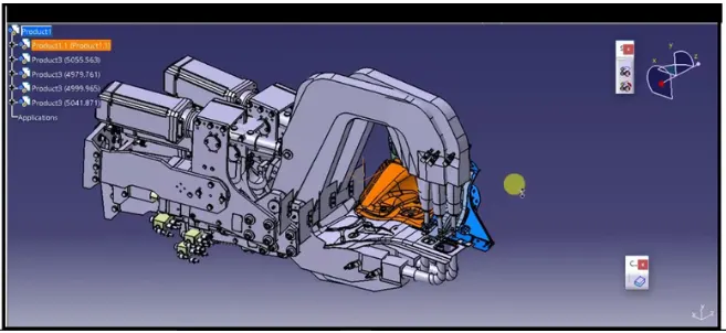
-In weld gun study the gun which is used in spot welding is checked over the panel by using 3D software.
-The weld gun position is checked over the predefined spot welding points,where the gun is falls in fixture unit or not.
-If weld gun falls in fixture unit,then redesign that unit or reposition it.
-Fixtures are redesign if the gun falls to the fixture unit,the weld spot position remains same.
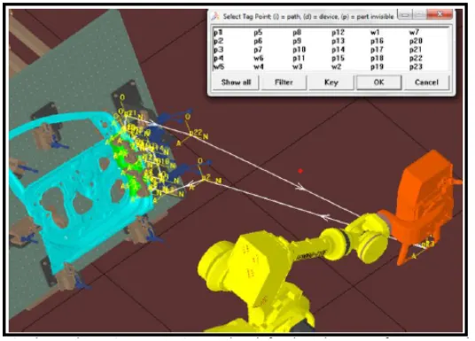
-The weld spots are define in prescribed location as shown in fig.The axis of weld spot along welding direction must be normal to the weld surface.To ensure this the weld spot co-ordinates are created using SURFACE option under tag s in layout menu.
-In the IGRIP layout,the motion destination position of a device model is represented by a tag point in a cartesian co-ordinate frame with N,O & A (X,Y&Z) axis.To calculate the position of a tag point in the layout,it is attached to a part model.
A.NO:-6
Weld gun study is very time consuming process,the entire welding cycle time study depends on the no.pf spots and weld gun study.
Below points are considered during gun study.
-The axis of weld spot along welding direction must be normal to the weld surface.
-The no,of weld spots for the panel,the time required to spot the each weld and the total time required to complete all weld spots.
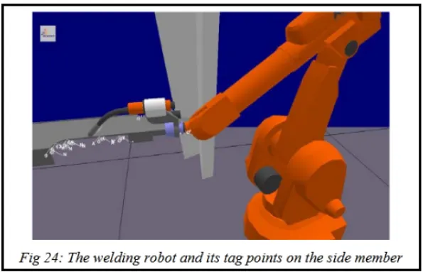
-If we have one or more device models and we want to program,the behaviour of each model in the work cell can be simulated over time.Instructions for each devices are coded by giving sequences,the sequence define the motion,manupulation and action of the devices.Based on the distance of each tag point from home position ,motion type,speed and acceleration one can obtained cycle time for each device assigned with sequences.This way robot cycle time was calculated precisely.
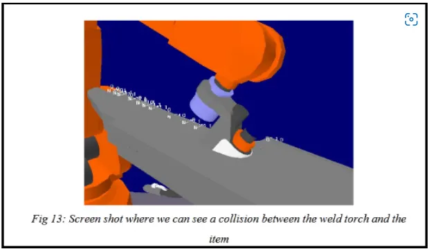
-After sequencing all the devices a simulation is run with collision check and make sure that the welding operation is collision free.
A.NO:-7
-Pneumatic system should be efficent and leak free.Some times they are not because of improper tube line routing,the result is either lack of knowladge,cornerss cut on planning time,or both.
-If routing is not done properly then,maintenance will not done efficently after any error or leak.
-Routing pipe line is a time ivestment,but can have big ROI especially for complexs system.During system design routing should be developed as the next step after sizing the tube lines and selecting the appropriate fitting.
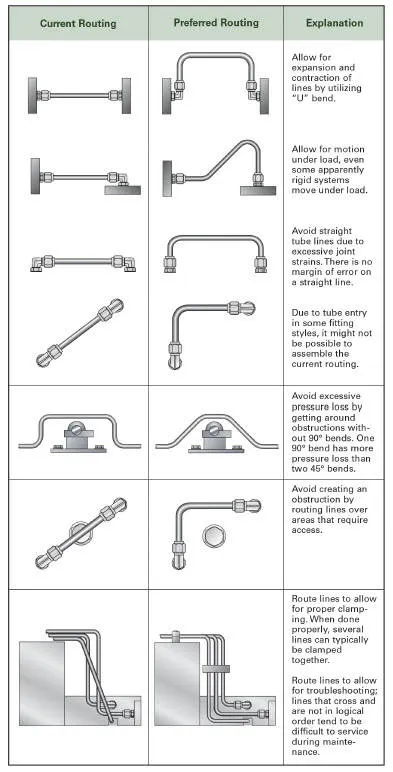
Below are guide lines for appropriate pneumatic pipe line routing:
-Employ U-bends to allow for line contraction and expansion.
-For pressure drop calculation use software tools.
-Include offset bend to allow for motion under load,regardless of how rigid the system seems.
-Favor bends rather than straight tube lines,because a straight line tube assembly with no bends like the example of the test stand mention above,can cause joint stain which may lead to leacking.
-Make sure routing design is allows room for assembly of any connections required.
-Minimize pressure drop by getting around obstructions with a few 90deg bend as possible,one 90deg bend has more pressure loss than two 45deg bends.
-Rout lines around rather than over areas that required regular access or maintenances.
-Keep troublshooting and maintenance in mind,focus on logical design and avoid cross lines.
A.NO:-8
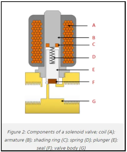
A solenoid valve consists of two main components,a solenoid and a valve body.A solenoid has an electromagnetically inductive coil,(A)around the iron core around the center plunger(E).At rest it can be normally open (NO) or normally closed(NC).In the de-energized state,a normally open valve is open and a normally closed valve is closed.When current flows through the solenoid,the coil is energzied and creates a magnetic field.This create a magnetic attraction with the plunger,moving it and over coming spring(D)force.If the valve is normally closed,the plunger is lifted so that the seal (F)opens the orific and allows the flow of the media through the valve.If the valve is normally open, the plunger moves downward so that the seal(F)blocks the orifice and stops the flow of media through the valve.The shading ring (C) prevents vibration and humming in AC coils.
Solenoid valves are used wherever fluid flow has to be controlled automatically. They are being used to an increasing degree in the most varied types of plants and equipment. The variety of different designs which are available enables a valve to be selected to specifically suit the application in question.
Direct acting solenoid valve
With a direct-acting solenoid valve, the seat seal is attached to the solenoid core. In the de-energized condition, a seat orifice is closed, which opens when the valve is energized.
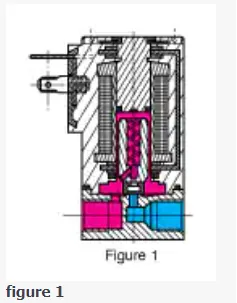
Direct acting 2-ways solenoid valve
Two-way valves are shut-off valves with one inlet port and one outlet port (Fig. 1). In the de-energized condition, the core spring, assisted by the fluid pressure, holds the valve seal on the valve seat to shut off the flow. When energized, the core and seal are pulled into the solenoid coil and the valve opens. The electro-magnetic force is greater than the combined spring force and the static and dynamic pressure forces of the medium.
Direct acting 3-ways solenoid valve
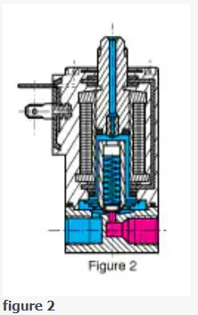
Three-way valves have three port connections and two valve seats. One valve seal always remains open and the other closed in the de-energized mode. When the coil is energized, the mode reverses. The 3-way valve shown in Fig. 2 is designed with a plunger type core. Various valve operations can be obtained according to how the fluid medium is connected to the working ports in Fig. 2. The fluid pressure builds up under the valve seat. With the coil de-energized, a conical spring holds the lower core seal tightly against the valve seat and shuts off the fluid flow. Port A is exhausted through R. When the coil is energized the core is pulled in, the valve seat at Port R is sealed off by the spring-loaded upper core seal. The fluid medium now flows from P to A.
Internally Piloted solenoid valve
With direct-acting valves, the static pressure forces increase with increasing orifice diameter which means that the magnetic forces, required to overcome the pressure forces, become correspondingly larger. Internally piloted solenoid valves are therefore employed for switching higher pressures in conjunction with larger orifice sizes; in this case, the differential fluid pressure performs the main work in opening and closing the valve.
Internally Piloted 2-ways solenoid valve
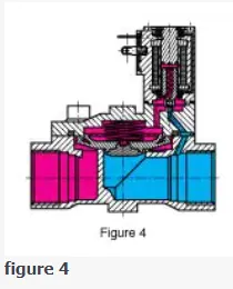
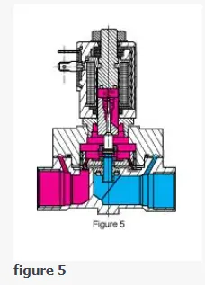
Internally piloted solenoid valves are fitted with either a 2- or 3-way pilot solenoid valve. A diaphragm or a piston provides the seal for the main valve seat. The operation of such a valve is indicated in Fig. 4. When the pilot valve is closed, the fluid pressure builds up on both sides of the diaphragm via a bleed orifice. As long as there is a pressure differential between the inlet and outlet ports, a shut-off force is available by virtue of the larger effective area on the top of the diaphragm. When the pilot valve is opened, the pressure is relieved from the upper side of the diaphragm. The greater effective net pressure force from below now raises the diaphragm and opens the valve. In general, internally piloted valves require a minimum pressure differential to ensure satisfactory opening and closing. Omega also offers internally piloted valves, designed with a coupled core and diaphragm that operate at zero pressure differential (Fig. 5).
Internally Piloted Multy-ways solenoid valve
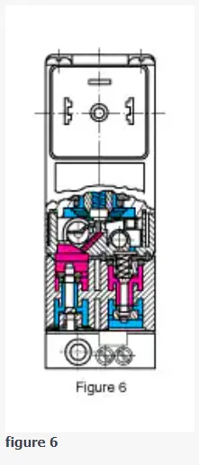
Internally piloted 4-way solenoid valves are used mainly in hydraulic and pneumatic applications to actuate double-acting cylinders. These valves have four port connections: a pressure inlet P, two cylinder port connections A and B, and one exhaust port connection R. An internally piloted 4/2-way poppet valve is shown in Fig. 6. When de-energized, the pilot valve opens at the connection from the pressure inlet to the pilot channel. Both poppets in the main valve are now pressurized and switch over. Now port connection P is connected to A, and B can exhaust via a second restrictor through R.
Externally piloted valve
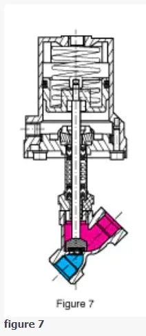
With these types an independent pilot medium is used to actuate the valve. Fig. 7 shows a piston-operated angle-seat valve with closure spring. In the unpressurized condition, the valve seat is closed. A 3-way solenoid valve, which can be mounted on the actuator, controls the independent pilot medium. When the solenoid valve is energized, the piston is raised against the action of the spring and the valve opens. A normally-open valve version can be obtained if the spring is placed on the opposite side of the actuator piston. In these cases, the independent pilot medium is connected to the top of the actuator. Double-acting versions controlled by 4/2-way valves do not contain any spring.
A.NO:-9
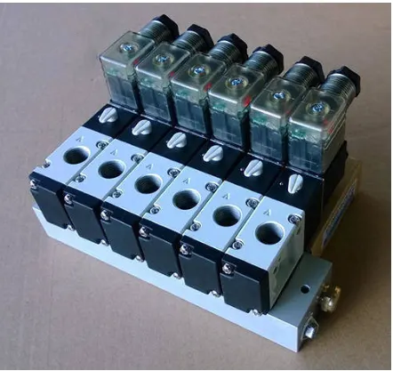
Valve bank is the arrangement of no.of solenoid valves .Valve bank will have common inlet port.A single servo line to each of the pneumatic valves,and independent valve passeages for each solenoid valve.On the solenoid bank each of the solenoid valves separeately controls the speed of high pressure servo air to a single pneumatic valve.The valve is actuated by selectively energzied the corresponding solenoid to allow servo air port of the valve.To return the valve to its fail safe position,the solenoid is de-energzied to vent the servo port of the valve to ambient.
Features and benefits:
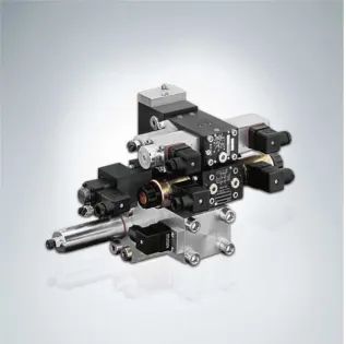
- Sub-plates for fexible combination of directional valve types with NG 6 (CETOP) standard connection pattern.
-Valve bank can be flange mounted directly on the connection block of a compact hydraulic power pack or connected as a separately arranged valve bank for pipe connection.
-Pressure switches and/or any other monitoring elements can be connected directly.
-Additional elements, such as orifces, throttles and check valves for connections P, R, A and B can be integrated.
-Hydraulic accumulator can be mounted directly.
A.NO:-10
-A sensor is a device that detects and responds that some types of input from the physical environment.The specific input could be light,heat motion,moisture,pressure or any one of a great no. of other environmental phenomenona,In a mercury based glass thermo meter,the input is temperature.
-A unit to design sense the car panel using electrical sensors is called sensor unit.It is designed to sense car panel using electrical sensor.This signal the sensor will be feed to the PLC and so next process will executed.
-Sensor units are used actually in sensing whether the panel are there or not or perticular component are there or not.Suppose there 10nos of part required for assembly then we have that no of sensors atleast.Whenver operator manually assemble entire component they do the process like fastening,Gluing.the sensor will show that perticular component is there or if component is missing will provide error.
Sensors used in automation
-In the industrial automation,sensor plays a vital part to make the products itellectual exceptionally automatic.These permit one to detect,analyze,measure and process a variety of transformations like alteration in position,length,height,exterior and dislocations that occures in the idustrial manufacture sites.
-These sensors also play a pivotal role in predicting and preventing numerous potential proceedings,thus catering to the requirments of many sensing application.
-The various types of sensor used in automation industries are proximity sensors,Vision sensors,Ultrasonic sensors,Position sensors,Photoelectric sensors,Temperature sensors,Inclination sensors etc.
-The applications for position sensors as a whole are broad.They can be used in anything from motion control of a robot, tank level sensing or even in semiconductor process equipment.
-Displacement sensor used in precision of objects at the nanometer level and in the measurment of precision thickness of disk drives,assembly line testing and machine tool metrology.It is widely used in machining.
A.NO:-11
-There are several classifications of sensors made by different authors and experts.Some are very simple and some are complex.The following classification of sensors may already be used by an expert in the subject but this is a very simple classification of sensors.
-In the first classification of the sensors,they are divided to Active and Passive.Active sensors are those which require an external excitation signal or a power signal.
-Passive sensors on other hand do not require any external power signal and directely generated output response.
-The other type of classifications is based on the means of detection used in the sensor.Some of the means of detection are Electric,Biological and chemical.Radioactive etc.
-The next classification is based on conversion phenomena i.e the input and output.Some of the common conversion phenomena are Photoelectric,Thermoelectric,Electrochemical , Electromagnetic,Thermo optic etc.
-The final classification of the sensors is Analog and Digital sensors.Analog sensors are provide analog outputs i.e the contineous output signal with respect to quantity being measure.
-Digital sensors in contrast to Analog sensors,work with discreat or digital data.The data in digital sensors,which is used for conversion and transmission,is digital in nature.
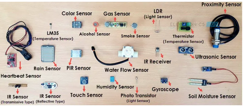
Different types of sensors are
- Temperature sensor
- Proximity sensor
- Accelerometer.
- IR sensor (Infrarred sensor)
- Pressure sensor
- Light sensor
- Ultrasonic sensor
- Smoke,Gas and Alcohol sensor
- Touch sensor
- Color sensor
- Humidity sensor
- Tilt sensor
- Flow and Level sensor
A.NO:-12
-Sensor unit is design to sense the car panel,by using electrical sensors which are being welded tool.
-The signal form sensors will be feed to PLC and so the next process will be executed.
-Each panel should be sensed by 1-2 sensor depends on size of panel,preferred to be in digonal opposite ends of panel.For example if 10 panels are in assembly,so there should be atleast 10 sensors used.
-Sensor should be used to prevent accidents.
-Every sensor should be mounted in 3-directions adjustable way in general.
-Some major sensor manufactures are IFM,SICK,OMRON etc.