Week 2:- BiW Fixture Basics Challenge
1.For a project we assign tasks and responsibilities,so that we execute a systmatic plan to avoid crucial failure and risk.The stages of activities are define below.
- RFQ-Request for Queation is noting but the voice of customer where customer demand his requirments by documentation format,such as technical offer,commercial offer,project time line,APQP,DFMEA etc.
- 1st Spec.Discussion Meeting-After finalize RFQ ,a meeting is conducted internally to discuss Time line and inhouse facility for this project,based on technical offer released.In this meeting concept design,2D drawing,Manufacturing, Assembly,Quality,Installation data are finalize.
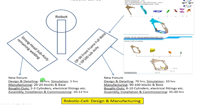
- Offer submission- After finalize technical offer,commercial offer will release based on technical offer and submitted to customer.So that customer will finalize offer comparison to other offers relatively.
- LOI/PO Recipt- In this stage customer will finalize best offer according to his suitability and release PO(Production Order) to conform this project handover to you.
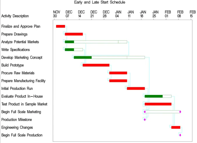
- Schedule preparation- After getting PO in hand project will start countdown from this date,so that we prepare schedule and planning activities.Schedules are created based on how much time should taken to complete activities like concept design,3D-Design,Simulation,2D-Design,Manufacturing,Assembly etc.
- BOM Preparation-A complete list of items is created to build a product is call BOM(Bill Of Material),so a list of items is generated i.e standard part items or purchase items.
- Design concept preparation-I this stage design team should focus on customer demands and prepare a concept design for customer approval.For example- A full fixture and Robot set up required for welding in car panel,so in design stage we consider fixture holding load,welding itself load act on panel,Robot set up and its movement,welding Gun movement according to customer initial requirment to avoid any collison.Considering all activities designer present the concept layout for approval.
- Customer Approval- After get concept design layout customer will review the concept and finalize this concept is better or need further correction,so that concept will finalize.
- Detailing and Drawing Release- After concept design is finalize a detail drawing(2D) is released with all the dimensions and GD&T symbol for more clarity about parts design.Customer approval and drawing released are the sametime contineous process,within this there is revisions are added upto the final approval.
- Manufacturing/BOP Ordering- After drawing finalize the parts are going to manufacturing(To get its physical shape from rawmaterial)as well as standard parts(Nut,Bolt,Shim,Washer etc),child parts (sensor,cylinder etc.)are ordered as per design specification.
- Mechanical/Electrical assembly- After get all the finish good parts conform by Process and Incoming Quality,they are goes for assembly as per design to get functionally active .The assemby consists up Mechanical type,Electrical type,Embbed type etc.
- Quality Inspection-After assembly done, quality should check final inspection as per drawing as well as functionally working condition,that meet all the requirment of customer.
- Internal Trial- After all inspection done,final assembly goes for inhouse trail run,in which all conditions are obserbed i.e fixture clamping perfectly by sensor or not,seating of car panel done correctly with guided pins,Robot movement and welding done perfectly etc.
- Online Trial- After trail ok by manual we go for automatic trial through HMI control panel.The automatic sequence operation checked by this trail.
- Packaging- After all trial done product is ready for customer end,so without harm any asthetical look or avoid any collision/crash packaging must provide for product as required by customer.
- Dispatch- After packaging done as per customer ,product will handover to logistic team and deliver to customer end.
- Installation as per layout- After customer get product,the proper installation and labeling required by designed layout.The fixtures and robots should be their proper sequence postion as conform at initial concept stage.
- Trails & Training at Customer- Production trial done through manual and automatic at customer end to satisfy all the functional requirments as well as training provided for staff and oprator for handling machine with caution through operator mannual.
- Buy off Meeting- At final meeting is conducted for satisfaction and review details. If any additional reqirement needed conform by this meeting.payment received in this meeting.
- Final Handover- In this stage all the related documents are handover to customer like BOMs,Standard part list,Signed master sample,Guide and mannuals etc.as per ISO/IATF.
2.Joining comprises a large number of processes used to assemble individual parts into a larger,It includes temporary joint like Mechanical fastening Nut,Bolt,pins etc.and permanent joint like Adhesive bonding,welding,Brazing etc.
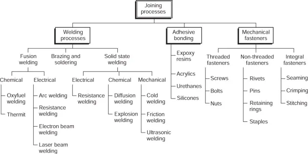
Welding-Widely used in manufacturing industries.It is a fabrication process in which two or more parts are fuse together in contacting surface through heat and pressure both form join by cool called welding.In this joining process the joint occure through only heat applied in two parts or both heat and pressure or filler material added in between two parts.
Advantages
- Welded joint has high strength, sometimes more than the parent metal.
- Different material can be welded.
- Welding can be performed anyplace, no need enough clearance.
- They give smooth appearance and simplicity in design.
- They can be done in any shape and any direction.
- It can be automated.
- Provide a complete rigid joint.
- Addition and modification of existing structures are easy.
Disadvantages
- Members may become distorted due to uneven heating and cooling during welding.
- They are permanent joint, to dismantle we have to break the weld.
- High initial investment.
Types of Welding-There is two types of welding Fusion and Solid state welding.
Fusion Welding:
Fusion welding is a process,that uses heat to join or fuse two or more materials by heating them to there melting point. The process may or may not require the use a filler material.When filler marerial is not used in process called autogenous welding. In this process substantial contact pressure is required during welding for sound joining.
Arc Welding-The power supply for the electric current is transferred from a welding electrode (or a “metal stick”) to the base metal, creating an “arc” that melts the metals upon contact.This process requires intense heat, and after the metals have cooled, a metallurgical bond is created, is called arc welding.The AC or DC power supply create intense heat around 6500°F to melt metal and join.
Rod types(Electrode)- The rod can either melt to become a part of the weld, known as consumable electrodes or it does not melt, known as non-consumable electrodes.
Consumable Electrodes: It melts down during welding and susequently deposite in weld bead,so electrode act as a filler material.After welding consumption it required change periodically.
- Shielded Metal Arc Welding(SMAW): In this process, the arc is placed between the metal rod that is electrode flux coated and the work segment to melt it and form a weld pool. The electrode flux coating on the metal rod is melted to form a gas, which shields the weld pool from the air. This welding process used in construct machine structure ,Ship building etc.
- Gas Metal Arc Welding(MIG/MAG): This form of arc welding is also known as Gas Metal Arc Welding (GMAW). MIG uses a shielding gas such as argon, carbon dioxide, or helium to protect the base metals from being destroyed from contamination.
3. Flux cored Arc Welding(FCAW): FCAW uses the gas formed by the flux to shield the work piece from contamination. This enables the operator to weld outdoors even if it is windy.It works by using a constantly fed consumable flux cored electrode and a continual voltage power supply in order to generate a constant arc length.This form of welding is great for general repairs and shipbuilding because it works well with thicker joints.

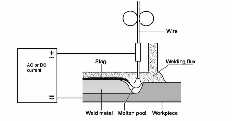
4. Submerged Arc Welding(SAW): This process creates a cover of fusible flux, which generates a protective gas to shield the work area. The process becomes conductive when molted and generates a current path amongst the electrode and work piece. The flux is great because it prevents spatter and sparks while simultaneously quelling fumes and ultraviolet radiation.This result slow cooling rate and improve weld quality.
Nonconsumable Electrode: It does not melts down during welding ,it remains intact throughout welding,so a separate filler material supply for welding.
- Gas Tungsten Arc Welding(GTAW):TIG uses a non-consumable tungsten electrode to generate an electric arc. The arc also works as a shield of gas to protect the weld from the air, which can cause oxidation. This is a favored method for welding aluminum.
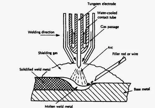
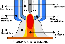
2. Plasma Arc Welding(PAW):The electrode is placed in a torch and the plasma forming gas is separated from the shielding gas, which produces narrow and deep welds.Plasma is then forced through a fine-bore copper nozzle which constricts the arc.This welding used both key hole and non key hole welds.
Resistance Welding- The weld is made by conducting a strong current through the metal combination to heat up and a force is always applied before, during, and after the application of current to confine the contact area at the weld interfaces and, in some applications, to forge the workpieces. Nonconsumable electrode use in this process.
Solid state Welding Process:
In these processes, bonding is achieved through deformation and diffusion at certain pressures and temperatures by using mechanical, electrical, or thermal energy.No filler metals, flux, or shielding gas is required during solid-state welding process. It prevents many metallurgical problems such as porosity, formation of brittle phases and enables to produce welds with a minimum distortion.
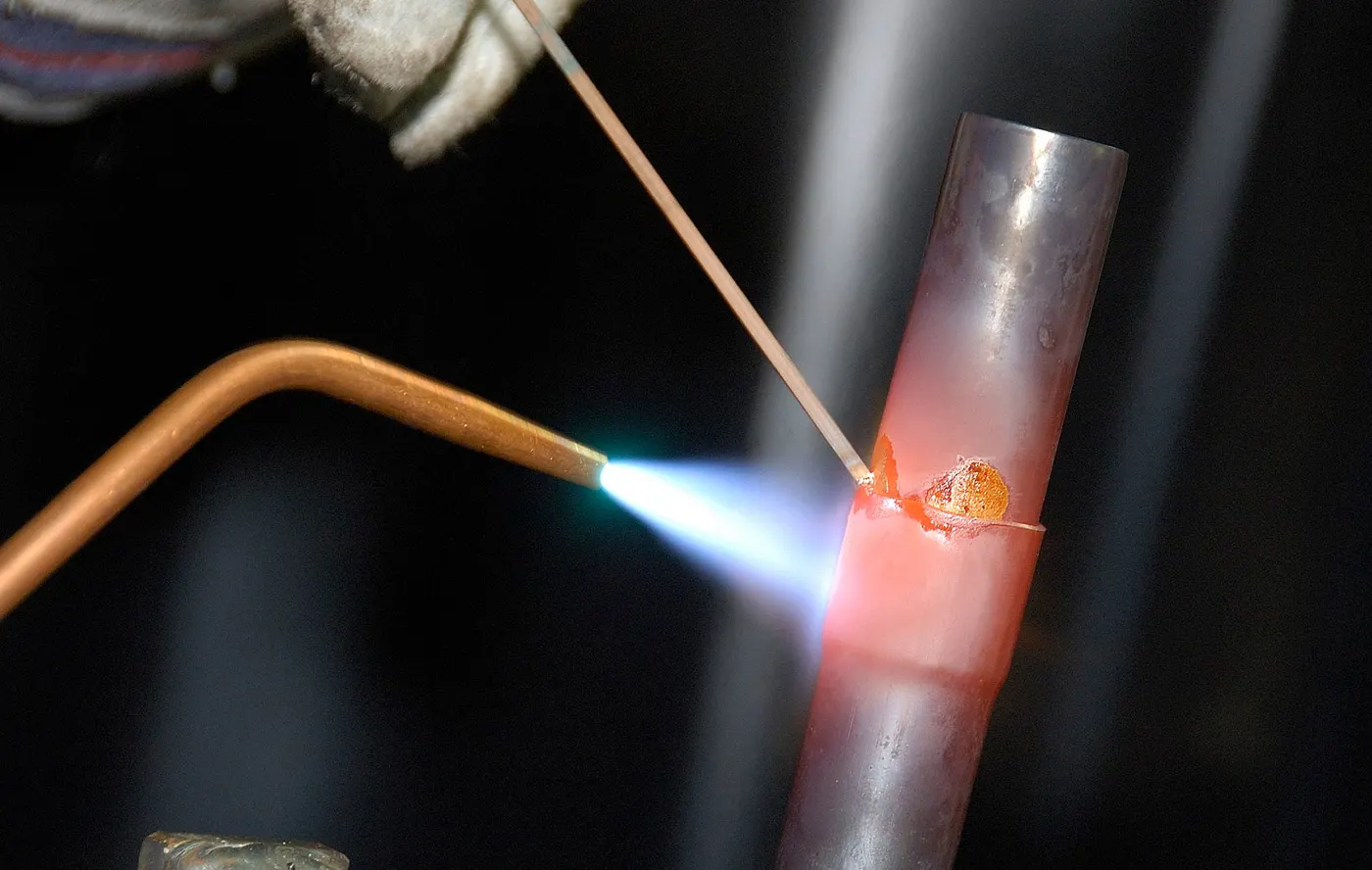
Brazing:In this process joining happens with addition of filler materials and appliction of heat.copper and silver based alloy are used for filler materials.Filler metal melts and flow by capillary action to deposite between two parts and cool to join. The parts joined by brazing are cleaned of oil, dirt or oxides and clearances between mating surfaces are very small. Base material remains same as filler material melts to join.Main advantages in this process is join can happen between disimilar base materials.
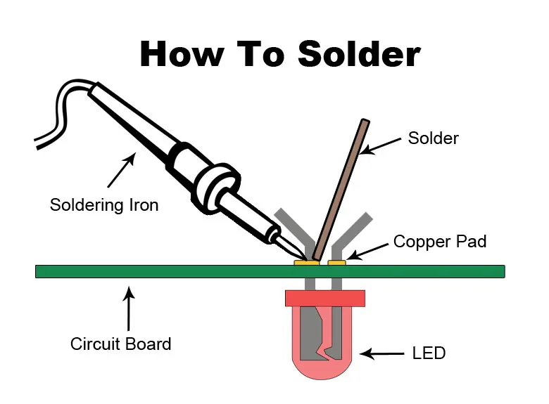
Soldering:Soldering is a joining process used to join different types of metals together by melting solder. Solder is a metal alloy usually made of tin and lead which is melted using a hot iron. The iron is heated to temperatures above 600 degrees fahrenheit which then cools to create a strong electrical bond.solddering process same as brazing process.
ADHESIVE BONDING
It is a permanent joining process,the technique involves glues,epoxy resin,silicons or various plastic agents that bond by evaporating of solvents or by curing heat,pressure and time.Addhesive bonding widely used in auomotive industries like such as windshield,Brake shoes etc.
MECHANICAL FASTENING
It is a temporary joining process where high fatigue life is critical compared to static strength.This joining process of materials provides long life of tools such as Screws and Bolts.
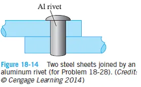
Riveting-It is also a mechanical joining process where a semi tubular rivet clinch the sheets by pressure force in pre hole position..It is a single step technique and joint process occure in a specific point of sheets.
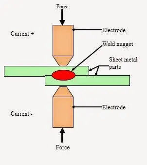
3.Resistance Welding: Resistance Welding is a both heat and pressure welding technique operate using high current and low voltage.Noncosumable electrode are used for this process and weld nugget are produced during the process.It is a Thermo-Electric process,high electric resistance use to generate heat.Amount of Heat(H) produced is depend on Resitivity(R) of material,Surface condition,current (I)supply and Time(T) denoted as H=I2RT.
Types of Resistance Welding:
Resistance Spot Welding
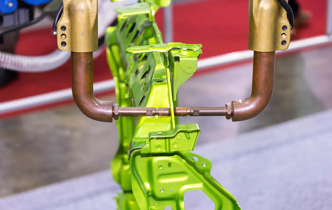
Spot welding is a one of the oldest technique used in joining two or more sheetmetals without using filler.Two cylindrical electrodes contact and overlap of two sheetmetals resistance heating conmbine with pressure create spot welding.It is the most common joining process in high volume manufacturing lines and has the main joining process in the construction of steel cars for over 100 years.
Advantages
- It is among the most affordable option where extra material /filler cannot be used and performed without any special skill (Labour is affordable.)
- Automation and Robotic techniques are highly suitable for this process.
- Spot welding is a fast process compare to other welding process.It also strengthen the workpiece.
- Without burning through it spot welding can done easily and impossible to distort and wrap.
- Strength and durability in automobile depends on quality of Spot welting.
- Comparatively low cost and highly uniform.
Resistance Seam Welding:
The seam welding process is an adaptation of resistance spot welding and involves making a series of overlapping spot welds by means of rotating copper alloy wheel electrodes to form a continuous leak tight joint.The rotating alloy wheel electrodes maintain constant speed and force throughover the surface.This process is used to making fuel tank and radiators where leak proof are required between the sheetmetals joint.
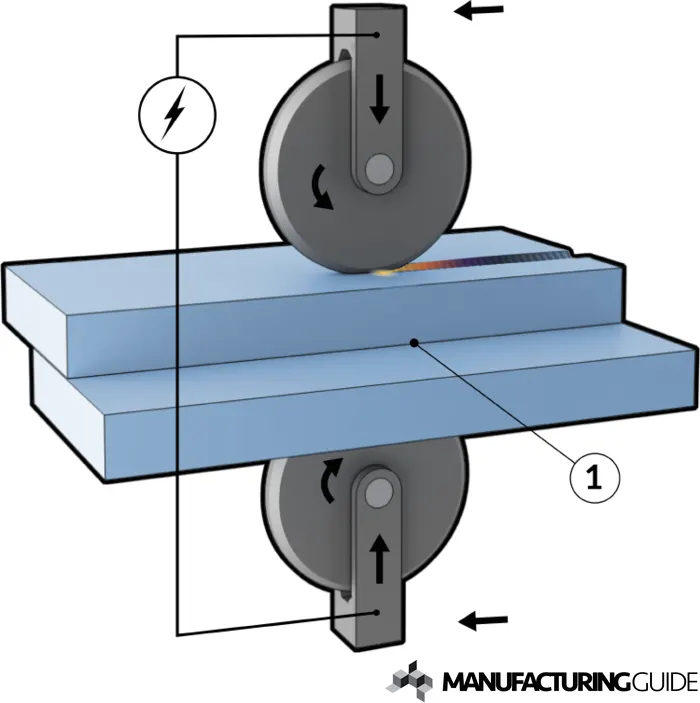
- It is mostely used in container,Radiators and Heat exchangers manufacturing company as it creates tight seal joint between two sheetmetals.
- No filler and flux materials are need this welding process.
Resistance Projection Welding:
It is a type of resitance welding where projection or embossing joints are used for the purpose the welding.When welding a workpiece of uneven thickness, projection is made into a thicker workpiece, and welding projection for uneven materials is made into one with higher thermal conductivity.
When the workpiece is pressurized by the platens, these projections collapse and fuse and become weld pieces at the site of the projections, therefore a quality weld is formed, and two metal workpieces are successfully welded.
Advantages:
- These projection weldings require a very small supply of current; as less current passes through the electrodes, the life of electrodes increases. This process also requires less pressure for welding.
- Unlike spot welding, there are no limitations on the thickness of the metals to be welded.
- Unlike spot weldings, more than one spot can be made in a single operation.
- This process is suitable for automation.
- Filler metal is not used in this process. Hence, a clean weld joint is obtained in this process.
- This process is also effective in welding joint that is in complicated locations.
- This process gives good heat balances while welding.
Typical body structure assembly plants are based upon resistance spot welding technology as it is flexible, low-cost, fast, and can be applied to both aluminum-aluminum and steel-steel joints. However, resistance spot welding offers several interesting metallurgical challenges that must be addressed to form robust joints as advanced material alloys and combinations such as aluminum-steel are introduced. An introduction to joining in the automotive industry will be given with special emphasis on the metallurgy of resistance spot welding and the aluminum-steel spot welding process.
4. FUSION WELDING:
Fusion welding is a method that makes use of heat to combine or fuse two or more materials into a melting point by heating them. The method may involve the use of filler material, or it may not.Contact pressure is necessary for the sound joining during welding. Here is more on what is fusion welding.
GAS WELDING-It is a welding process that melts and join metals by heating them with a flame caused by a reaction of fuel gas and oxygen.Due to its high flame teperature most common method used called oxyacetylene welding.The flux melts ,solidifies and forms a slag skin on the weld metals at the time of joining process.
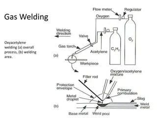
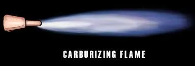
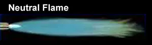
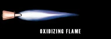
There are 3types of flames produce in oxyacetylene welding i.e
- After turn on,flame immediately changes into a long white inner area surrounded by transperant blue envolpe is called carburizing flame(3000deg celcius)
- On addition of little more oxygen a bright whities cone surrounded by transperant blue envolpe is called neutral flame(3200deg celcius)
- If more oxygen is added cone becomes darker and more pointed,so that envelop become shorter and sharper is called oxidizing flame(3400deg celcius)
Advantages:
- Portable and Most Versatile Process: Gas welding is probably portable and most versatile process.
- Better Control over the Temperature.
- Better Control over Filler-Metal Deposition Rate.
- Suitable to Weld Dissimilar Metals.
- Low Cost and Maintenance.
Disadvantages:
- Not suitable for thick sections.
- Gas welding tends to provide a low surface finish.
- Cannot be used for high-strength steel.
ARC WELDING- It is also a fusion welding process,where Direct current(DC) or Alternate current(AC) provided to create an arc between a electrode(consumable or noncosumable )and base material to melts the material and join together.Today, arc welding is still a key part of shipbuilding, and has other important roles in the automotive, construction and mechanical industries.
Sheilded Metal Arc Welding(SMAW)
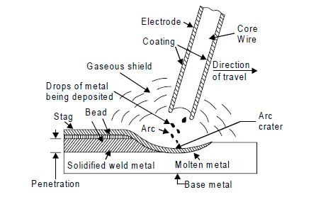
Shielded metal arc welding (SMAW) is a fusion welding process that uses a consumable, flux-coated electrode to create an arc between the electrode and the work piece. Molten metal travels from the electrode via the electrical arc and is deposited into the work piece. The flux coating is also melted and it surfaces on top of the molten weld pool in the form of slag.This process used in heavy duty work involved industries like carbon steel,High alloy steels etc.
Advantages:
-Can be used anywhere, outside, in the workshop & in the water.
-Quick set-up and very easy to set up.
-Can be used to weld all positions.
-Electrodes are readily available in many sizes and diameters.
-Low noise (rectifier).
Disadvantages:
-Every time you do the next welding, the slag must be cleaned.
-Cannot be used for welding non-ferrous steel materials.
Gas-Tungsten Arc Welding(GTAW)
During this welding process, a nonconsumable tungsten electrode is used. The weld torch and tungsten are cooled and protected with an inert shielding gas (like helium or argon), just like with gas metal arc welding, also known as gas tungsten arc welding.
Advantages:
-Clean and highly weld quality
-No slag,no smoke,no spark while weld wide range of materials.
Disadvantages:
-Low deposition rate,required high level of operation skill.
-High level of UV rays.
Plasma Arc Welding(PAW)
In Plasma Arc Welding(PAW), a non-consumable tungsten electrode is used to produce arc. This arc heats up the inert gases which are provided from inner orifice around tungsten electrode. The heating temperature is about 30000 degree centigrade at which the gas converts into ionized form. This hot ionized gas further used to create a welding joint by fusion.This process used in marine and aerospace industries.
Advantages:
-High welding speed.
-High energy available for welding.
-The distance between tool and work piece does not effects the arc formation.
-High intense arc or high penetration rate.
Disadvantages:
-Higher equipment cost.
-Noisy operation.
Submerged Arc Welding(SAW)
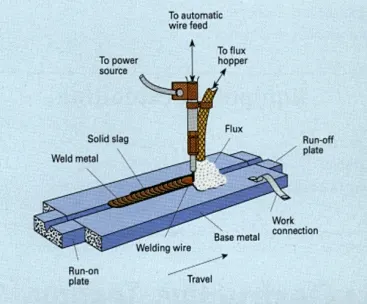
This is a fusion welding process,in which utilizes a bare consumable metallic electrode producing an arc between itself and the work piece within a granular sheilding flux applied around the weld.After that The arc heats and melts both the work pieces edges and the electrode wire. The molten electrode material is supplied to the surfaces of the welded pieces, fills the weld pool and joins the work pieces.
Advantages:
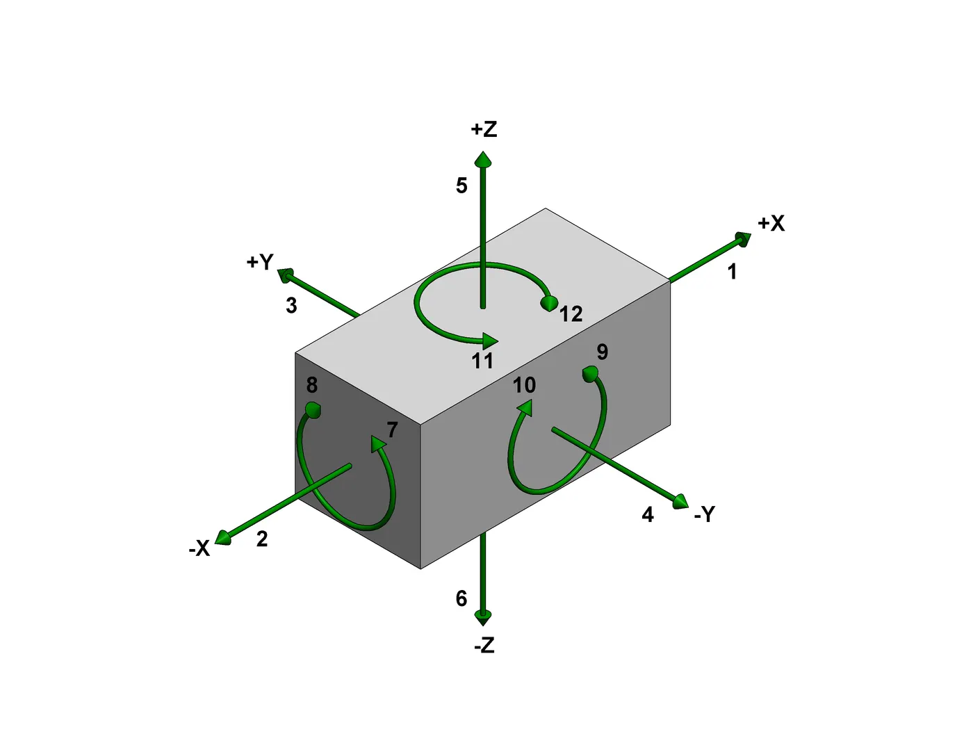
1. Accurately position the part at the desired coordinates.
2. Restrict all six degrees of freedom so that the part cannot move.