Week 7- Base Unit Design Challenges 2
BASE UNIT DESIGN
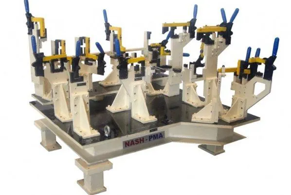
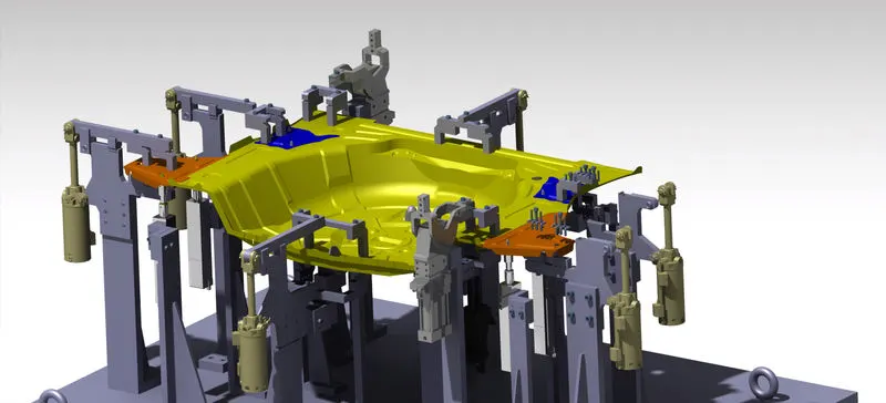
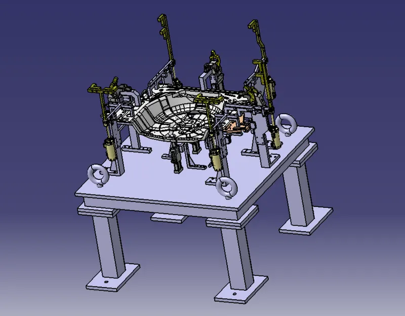
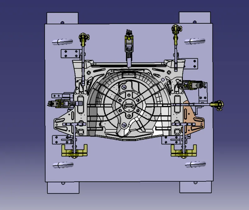
A base unit is the unit design to mount all the units like clamp unit,pin unit,rest unit etc,also all other parts like the penumatic valve box,Trunking cable path are mounted on it.
FUNDAMENTALS OF BASE PLATE DESIGN
- A base plate should cover all the units with its outer periphery including opening.
- A base plate is desgned to prefered with respect to BCS co-ordinate system.
- A base plate should be drilled with datum holes/meqasuring holes in line with a pitch of 1000mm in general.
- Number of datum holes depend upon the size of plate.
- Datum holes should be drilled at nominal value of co-ordinates,and in terms of 50&100mm in general.
- Example: X=100,Y=-600,Z=250
- Datum holes should be drilled with dia 100mm away from outer units.
- Datum holes should be covered with cover plates.
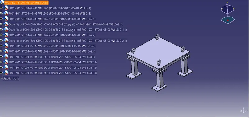
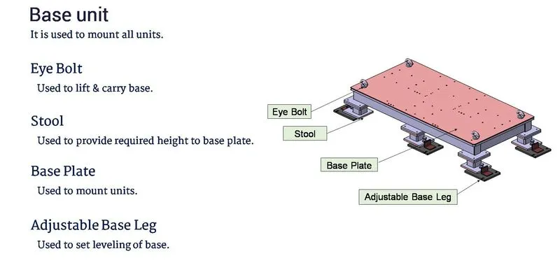
BELOW PARTS ARE DESIGNED FOR A BASE UNIT
3-2-1 PRINCIPLE:
-The 3-2-1 principle of location is used to constrained the movement of workpiece along the three axis i.e xx,yy,zz.This is achived by providing 6 locating points,3pins in base plate,2 pins in vertical plane and 1 pin in a plane which is perpendicular to first two planes.
-The 3-2-1 principle is the heart of thr fixture design and world holding device.In BIW fixture design the panel are always fixed with the help of 3-2-1.Because it always minimize unwatend components to hold the panels.With the help of 3-2-1 principle we can arrest the degree of freedoms which means six degrees of rotational and six degrees of translational axis.
1st-Plane
Illustrating best stool example which is get 3points support for stable,so 1st plane taken 3pins support to arrest the maximum DOF of a object.Now it can move in X,Y and rotate about Z axis.
- Use the largest surface of the part for the 1st reference plane.
- Position the three support points as far as possible.
- If more than 3points are required to prevent deflection make the additional point for adjustable.
2nd-Plane
This plane perpendicular to the 1st plane and define by 2points.The part is now constraints to one DOF movement along the Y-axis(The part canot move along X,Z axis because it is held against the planes by clamping force.)
3rd-Plane
This plane is perpendicular to the first two planes can be defined by one point.The part is now entirely constraints.It cannot move along and rotate about X,Y and Z axis.
BEFORE DESIGNED UNITS
PIN UNIT
The purpose of pin unit design is necessary to have 2pins to locate a car panel and here one pin must have arrest 4ways (4 translational) and other arrest 2ways(2 rotational) of a car panel by using 3-2-1 principle.
There is 2types of pin units:
1-Fix pin unit.
2-Retractable pin unit.
Fix pin unit
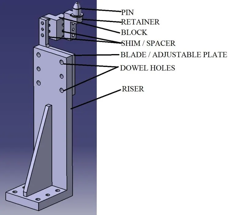
Fix pin unit consists of pin,pin retainer,blade,block,shims and riser.
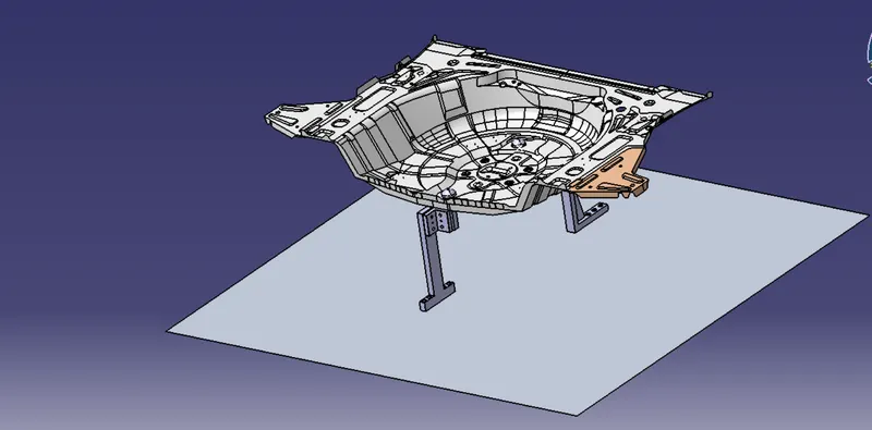
Different types of parts in pin unit design as shown in picture-
Fundamentals of pin unit design-
- It has necessary to have 2pins to locate car panel and here one pin can arrest 4ways (4 translational)and other arrest 2ways(2 rotational) for the car panel.
- The axis of car panel hole and the axis of pin should be same.
- Pin tolerance for a geopin should be closer i.e -0.15mm and for re-spot pin is -0.28mm.
- Pin should engage 3-5mm from car panel entry surface.
- All pin should accomdated with 2ways adjustable shims ierespective the direction of arresting.
- Round pin should be used 4ways and 2ways arresting of the car panel for round hole and slot respectively.
- Dimond pin should be used 4ways and 2ways arresting of the car panel for slotted hole and round hole respectively.
PINS:
- Pin is the part in which car panel is located,it can be designed part or also a standard part.
- Pin should be grinding surface on a shaft in which below pin retainer will fitted.
- Pin must have provision like tapped hole from the bottom or V-grooved.
- A pin must have hardened and black oxide finished.
- The mounting surface of the pin should be finely machined surface.
- The pin must have a step machine surface to lock the rotation,which matches the pin retainer.
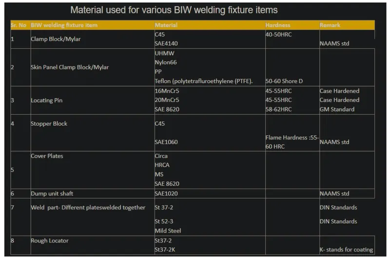
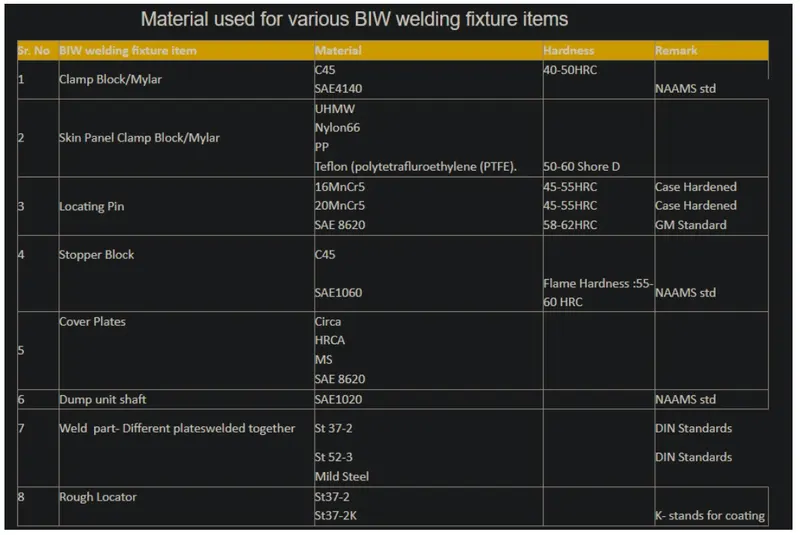
Different types of material used for different fixture parts are listed below:
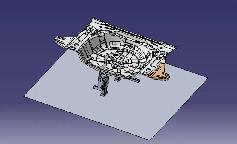
Retractable pin unit
In this unit pin move up and down by a cylinder.It is also locat car panel by using pins,which has same function as fixpin unit,but the entire pin package mounted on the retractable cylinder.
The Pneumatic/Hydraulic cylinders can be considered as follows-
-System operated with air,fluid,oil.
-Open/Closed loop system.
-Low/High pressure system.
-Cheaper/High cost comparision by operation.
CLAMP UNIT
The clamps are hold the panels tgrough clamp arm and manufacturing part and prevent from part distortion while carrying out the welding of panel.It consists up NC Blocks/Mylers/Riser by using a pneumatic cylinder.
When a cutting force is produced a load or moment on the workpiece,it is necessary that a sufficent clamping force is exerted to witstand such actions.To provide a suitable locking for acheiving the stability of location we provide clamp unit.
There are 2-types of clamp unit.
1-Power clamp unit.
2-Swivel clamp unit.
Power clamp unit
A clamp unit is a unit designed to clamp or hold car panel with NC Blocks/Mylers/Risers by using a penumatic cylinder.Clamp arm,Finger rest or back up,L-block,Shims,Riser,Pneumatic cylinder are the typical parts of clamp unit.Clamping force should be considered while designing clamp unit.
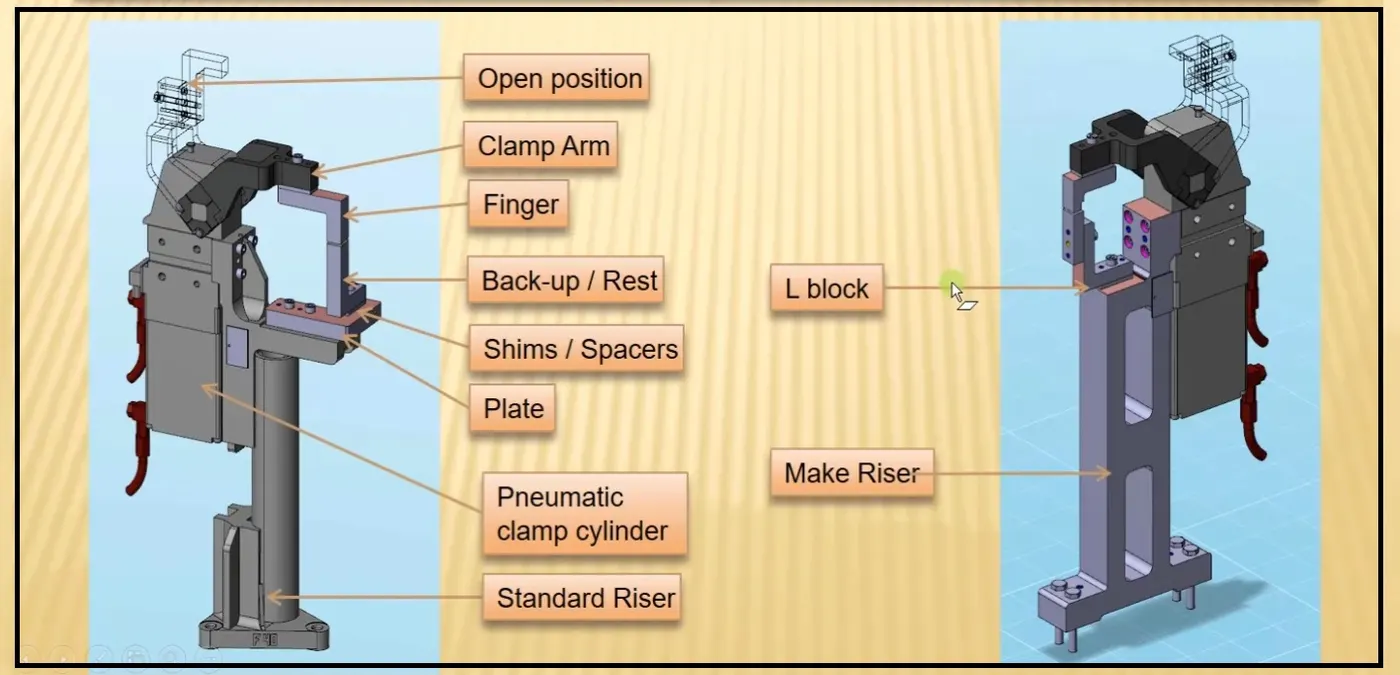
Factors should considered while designing clamp unit:
- There should be adequate space between cylinder and other parts like riser,car panel because cylinder moves/swings while loading and unloading or opening and closing.
- Pin clamp unit is used where 2panels or components are located and clamp for welding.
- Clamps make in such a way that it can clamp 2car panel at once.
- Clamp units has shims in one direction and pin clamp units has shims in both direction.
- All parts should snap and butt properly each other.
- Make sure that all the clamping unit parts are 10-12mm away from car panel,so that they do not damage the car panel.
- Design tree should be structured properly with easy identification.
- In this design 63D bore and 100mm stroke size Clevis clamp cylinder are used.
- Avoid any clash so that it cannot rise any issue in assembly.
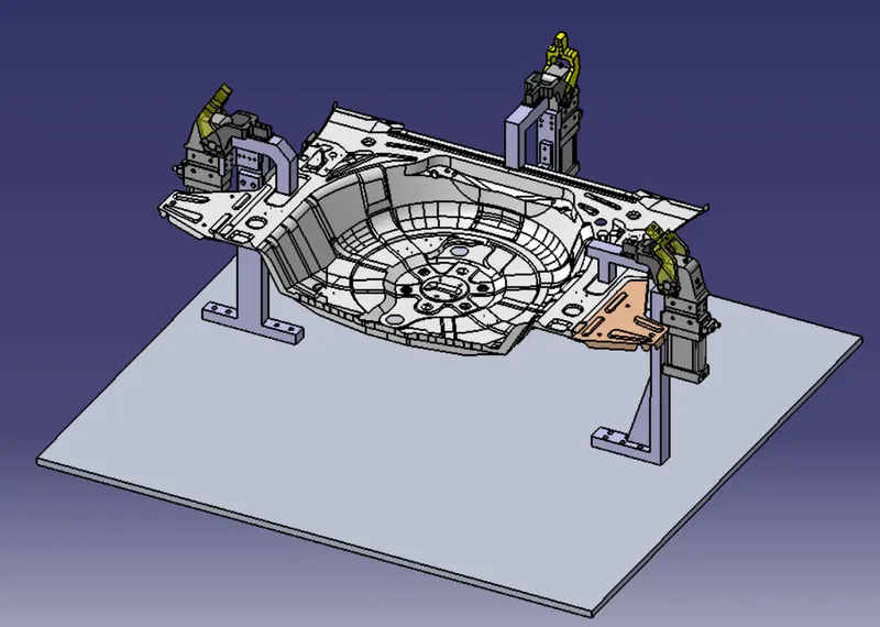
In clamp unit part materials used are belows-
Swivel clamp unit
A clamp unit is a unit designed to clamp or hold car panel with NC Blocks/Mylers/Risers by using a penumatic cylinder.Clamp arm,Finger rest or back up,L-block,Shims,Riser,Swivel cylinder are the typical parts of clamp unit which has same function of power clamp unit.Clamping force should be considered while designing clamp unit.
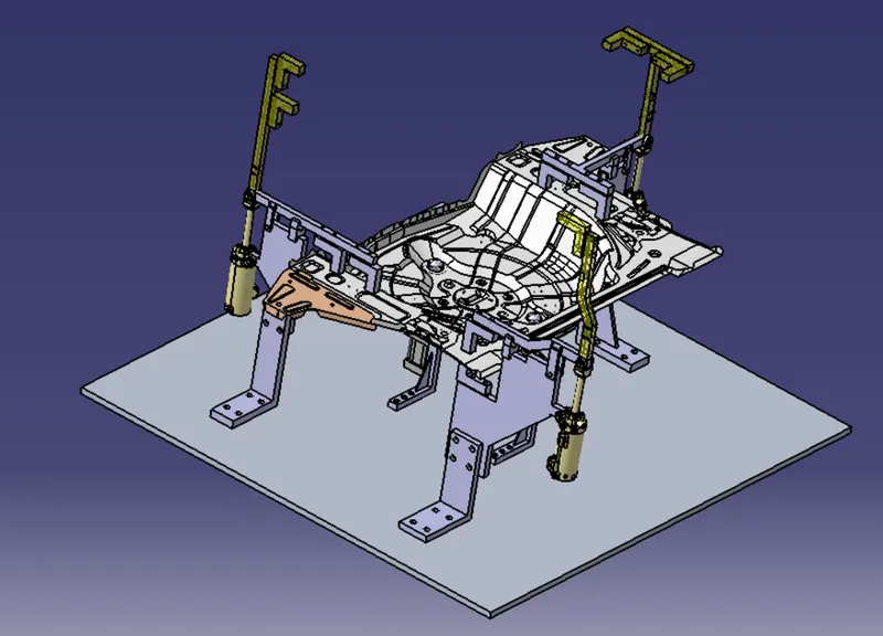
Clamp cylinder:
Clamp cylinders are bought out parts,some of the manufactures are Tunkers,Zytran,Festo,Steel smith in the clevis clamp cylinder.
We use swivel clamp cylinder- CKG1_B_63_100Y
CKG1-Series of cylinder.
B-Clevis width 19.5mm
63-Bore size.
100-Cylinder stroke.
Y-End bracket i.e doubble knukkle joint.
REST UNIT
A rest unit is used to support the car panel and also it resists the clampin force of the fingure with the help of rest mylers.
It consists of rest myler,shim packs,riser.
Holding force should be considering while designing rest unit.
Mostely to avoid excess part,reduce weight and also cost of fixture the rest unit is combined with clamp unit.
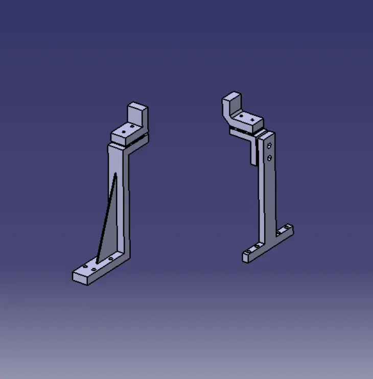
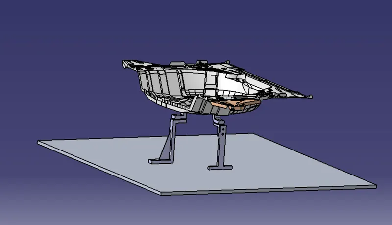
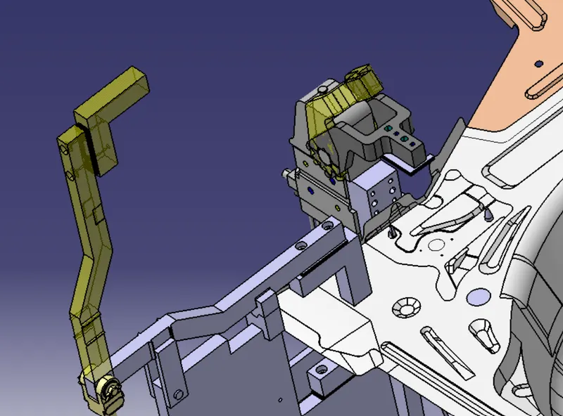
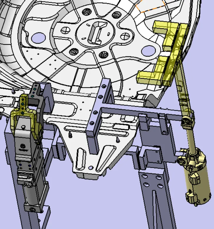
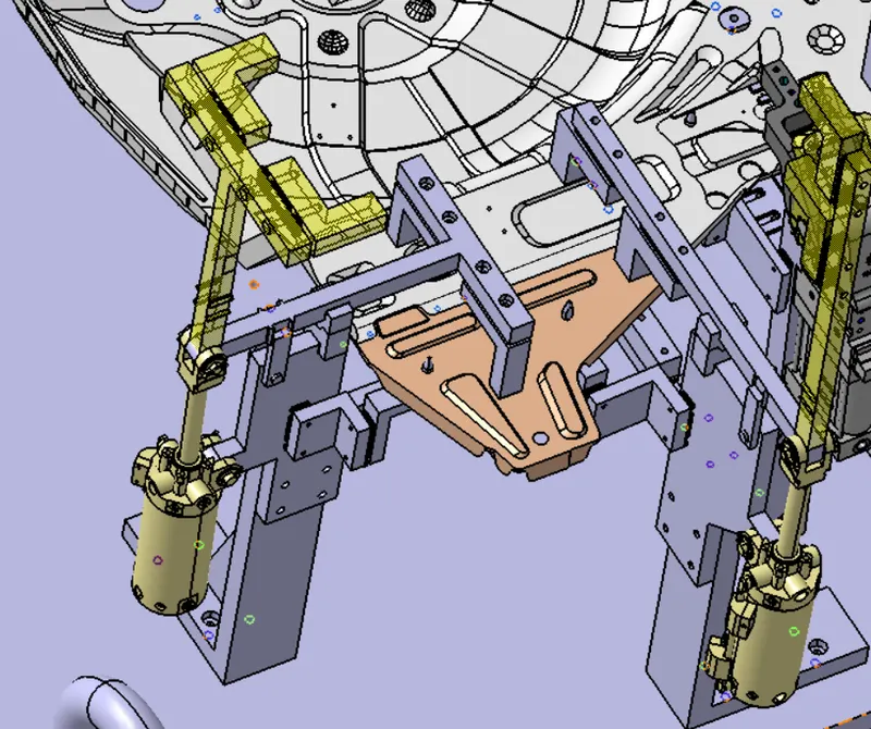
ASSEMBLY VIEW
TOP VIEW
FRONT VIEW
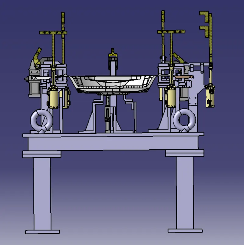
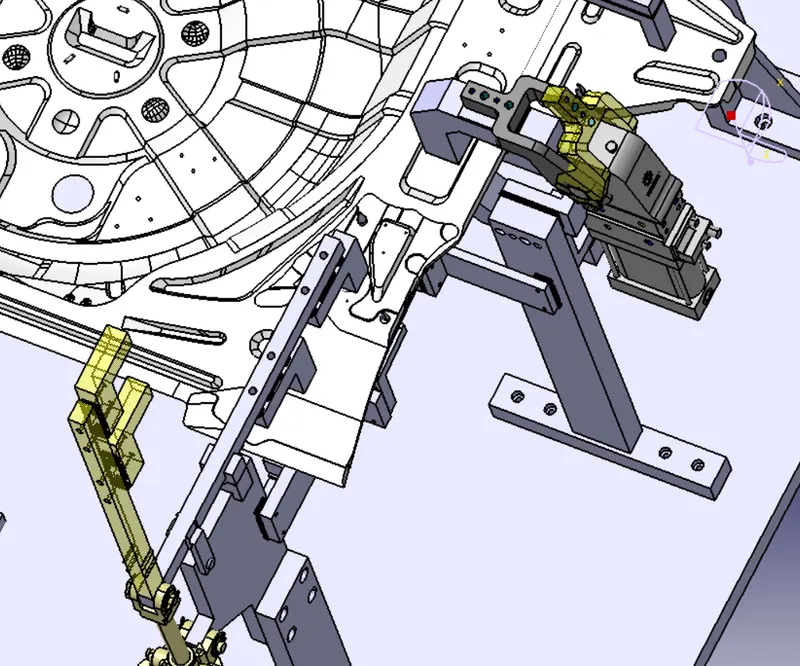
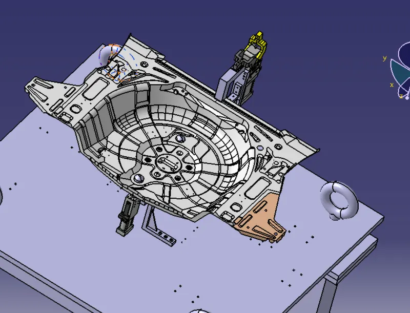
3-2-1 PRINCIPLE
YOU CAN OPEN THE COMPLETE FILE FROM BELOW MENTION PRODUCT FILE.
