Week 9:- 2D Detailing Challenge
1.Drawing Templates
Engineering is the graphical representation of structures,machines and their component parts that communicates the engineering intent of a technical design to the craftsman or worker who makes the product.
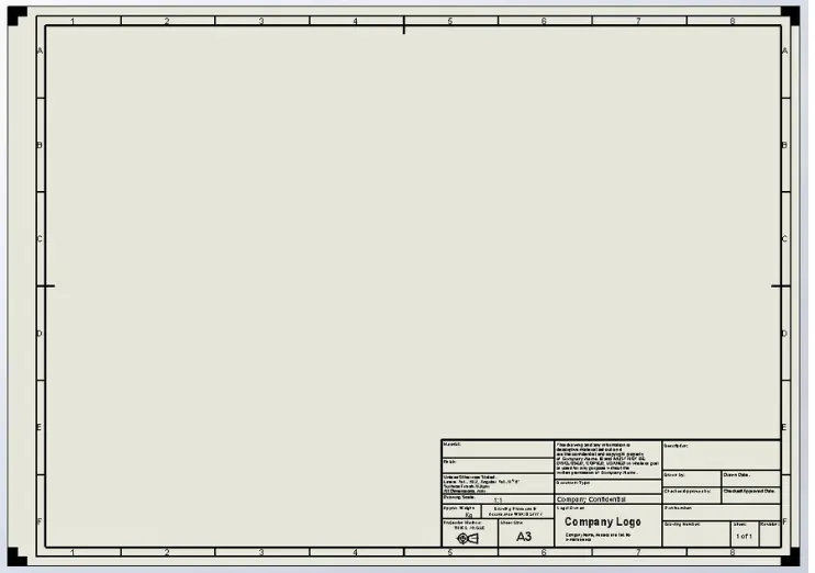
-Drawing templates are basically the drawing standards as per customers specifications.
-Drawing templates are format that are used for detailing of different parts or units of the fixture.
-There are 'n' numbers of details, that are already available on the template and are useful for various manufacturing processes,such as machining finish,Tolerances,Surfacetreatement,Material,Name of perticular part,Name of the assemblies etc.
-Prepare a drawing template at the start of the project can help save time.
-These templates can be used as a start model for detailing of different parts.
-Drawing templates also gives information about the angle of projection to be used,views to be considered,scalling of the drawing as per the part or unit.
Drawing sheet Contents
The title block is normally placed in the bottom right of the drawing frame,and it should contail the following information.
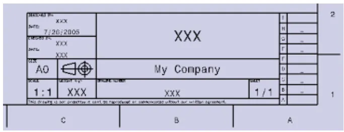
-Name of the company or organization.
-Title of the drawing.
-Drawing Number,which is generally a unique filing identifier.
-Scale
-Drawing size.
-Angle of projection used,either first/third which is shown symbolically.
-Signature or initials of draftsman,checker,approving officer and issuing officer,with the respective dates.
-Material of the part.
-Revision number.
-Sheet number for multi-sheet drawings.
-Other information as required(Tolerances,surface finish, etc.)
In addition to the information above,for the drawings produced using CAD software,it is highly recommended to have the following information in the title block.
-Name of the CAD software used and its version.
-Name of the drawing file.
-Name of the source part or assembly file.
-Unts of the dimensions.
2.Angle of projection
The angle at which an observer draw an object to convert it from 3D to 2D plane such as real object image to a plane paper is known as angle of projection.
Projection is the process or technique of representing a 3-Dimensional object by projecting all its points by straight linesd,either parallel or converging to a picture plane.
There are two types of Angle of projection,
-First Angle Projection
-Thired Angle Projection
Othographic projections are 2D representation of 3D objects.Feature of 3D parts are presented on a flat plane,as though the outlines of the part had been projected onto a screen.
The viewing angles are split into quadrants of first angle,second angle,thired angle and fourth angle.
In practice only first angle quadrant and the thired angle quadrant are used since these are pure views,The second angle quadrant and the fourth angle quadrant are combination of first and third angle projections and cause confusion to the reader.
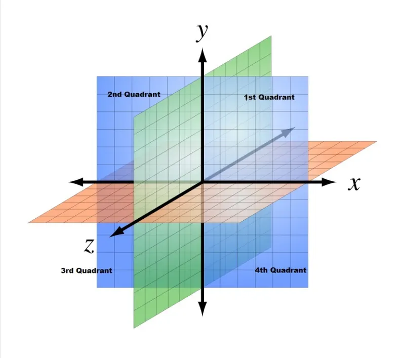
3.First and Thired Angle Projection
First angle projection and third angle projection are two different methodes of creating a 2D drawing of a 3D part.
First angle projection is commonly used in all countries other than united states.
It is mainly used in EUROPE and ASIA Countries.
The Indian Standard Institution(ISI) recommended the use of First Angle Prijection method now in all the institutions.
Thired Angle Projection is commonly used in USA.
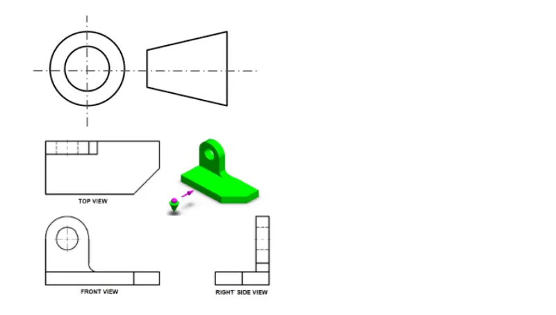
First angle projection
-The object is imagined to be in first quadrant.
-The object is lies between the observer and plane of projection.
-The plane of projection is assumed to be non transparent.
-When view are drawn in their relative position Top view comes below Front view, Right side view drawn to the left side of elevation.
-A First Angle Projection drawing is identified by the first angle projection symbol. The angle of projection symbol typically appears in angle of projection block near to Title block.
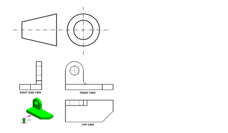
Third angle projection
-The object is imagined to be in third quadrant.
-The plane of projection lies between the observer and object.
-The plane of projection is assumed to be transparent.
-When view are drawn in their relative position Top view comes above Front view, Right side view drawn to the light side of elevation.
-A Third Angle Projection drawing is identified by the third angle projection symbol. The angle of projection symbol typically appears in angle of projection block near to Title block.
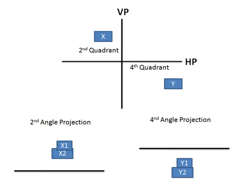
Second and Fourth angle projection
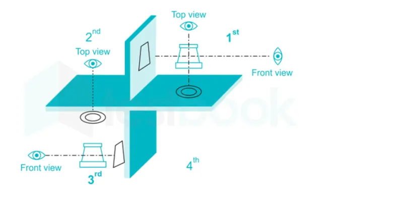
In Mechanical Engineering,drawings are made either in first angle projection or in third angle projection.We do not make drawings in second or fourth angle projection.When there are Vertical Plane (VP) and Horizontal Plane (HP) perpendicular to each other , we have 4 quadrants.
For 1st angle projection system, the object is placed in 1st quadrant, for 2nd angle projection system, the object is placed in 2nd quadrant and so on.
In Second quadrant, Vertical plane (VP) lies in between object and observer. Therefore front view of the object will lie on vertical plane whereas top view will lie on horizontal plane.
As per rule of projection when horizontal plane is rotated 90 degree in clockwise direction, top and front view will overlap.
Overlapping projection views create confusion in the drawing. Therefore 2nd angle projection system is not used.
Similarly when object is placed in 4th quadrant both top and front view will overlap. Therefore fourth angle projection is also not used.
4.Gemetrical Dimensioning and Tolerancing.(GD&T)
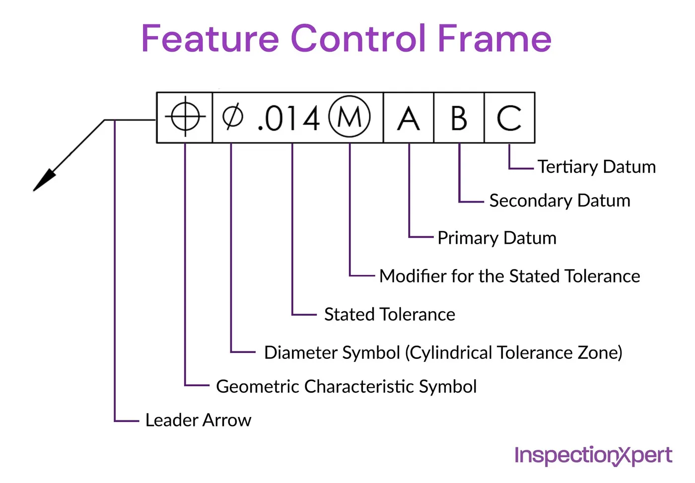
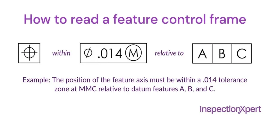
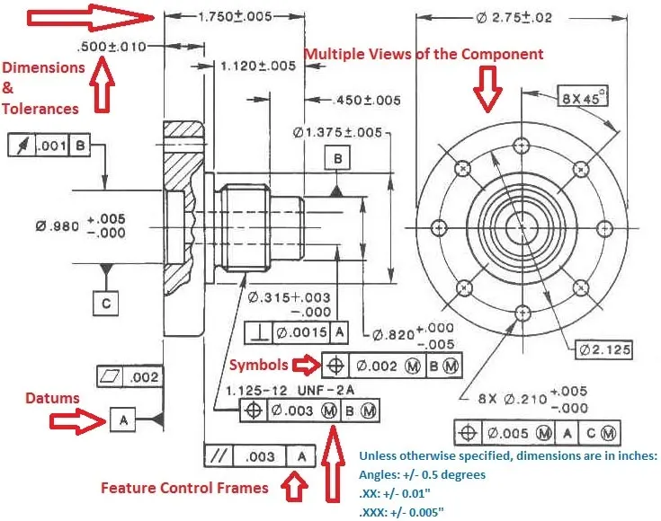
-Manufactured items differ in size and dimensions from the original CAD model due to variations in the manufacturing processes. To optimally control and communicate these variations, engineers and manufacturers use a symbolic language called GD&T, short for Geometric Dimensioning and Tolerancing.
-GD&T tells manufacturing partners and inspectors the allowable variation within the product assembly and standardizes how that variation is measured.
-GD&T, short for Geometric Dimensioning and Tolerancing, is a system for defining and communicating design intent and engineering tolerances that helps engineers and manufacturers optimally control variations in manufacturing processes.
-The most important benefit of GD&T is that the system describes the design intent rather than the resulting geometry itself. Like a vector or formula, it is not the actual object but a representation of it.
-For example, a feature standing at 90 degrees to a base surface can be toleranced on its perpendicularity to that surface. This will define two planes spaced apart, that the center plane of the feature must fall within. Or, when drilling a hole, it makes the most sense to tolerance it in terms of alignment to other features.
-Describing product geometry related to its intended functionality and manufacturing approach is ultimately simpler than having to describe everything in linear dimensions. It also provides a communication tool with manufacturing vendors, customers, as well as quality inspectors.
Benefits of GD&T
The language of geometrical dimensioning and tolerancing can be intimidated at first,but when used properly it can yeild many advantages such as,
- Standardized international system.
- More flexibility,particularly for complex shapes.
- Allows cylindrical tolerance zones.
- Datums are clearly define.
- Based on the fit and function of a part or assembly.
- Eliminates need for many notes.
- Allows for more tolerance.
GD&T Guidelines
-
Clarity of a drawing is the most important, even more so than its accuracy and completeness. To improve clarity, draw dimensions and tolerances outside of the part's boundaries and applied to visible lines in true profiles, employ a unidirectional reading direction, convey the function of the part, group and/or stagger dimensions, and make use of white space.
-
Always design for the loosest feasible tolerance to keep costs down.
-
Use a general tolerance define at bottom of the drawing for all dimensions of the part.Specific tighted and loosen tolerances are indicated in drawing when supersede the general tolerance.
- Tolerance functinal features and there interrelation first,then move on to the rest of parts.
- Whenever possible,leave GD&T work to manufacturing experts and do not describe manufacturing processes in the engineering drawings.
- Do not specify a 90 degree angle since it is assumed.
5.Symbols used in GD&T.
GD&T is feature based,with each feature specified by different controls.GD&T symbols fall in five categories.
Form Controls specify the shape of features,including
-Straightness is divided into line element strightness and axis straightness.
-Flatness means straightness is multiple dimensions,measure between the higest and lowest points on a surface.
-Circularity or roundness can be described as straightness bent into a circle.
-Cylindricity is basically flatness bent into a barrel,It includes straightness,roundness and taper which makes it expensive to inspect.
Profile Controls dedscribed the 3-dimensional tolerance zone around a surface.
-Line profile compares a 2-dimensional cross section to an ideal shape.The tolerance zone is defined by two offset curves unless otherwise specified.
-Surface profile creates through two offset surfaces between which the feature surface must fall.This is a complex control typically measured with a CMM.
Orientation Controls the dimensions that vary at angles,including
-Angularity is flatness at an angle to a datum and is also determined through 2 reference planes spaced the tolerance value apart.
-Perpendicularity means flatness at 90deg to a datum,It specifies two perfect planes the feature plane must lie in between.
-Parallelism means straightness at a distance.Parallelism for axis can be defined by defining a cylindrical tolerance zone by placing a diameter symbol in front of the tolerance value.
Location Controls define feature locations using linear dimensions such as,
-Position is the location of features relative to one another or to datums and is the most used controls for features.
-Concetricity compares the location of a feature axis to the datum axis.
-Symmetry ensures that non-cylindrical parts are similar across the datum plane.This is a complex control typically measured with CMM.
Runout Controls defined the amout by which a perticular feature can vary with respect to the datums,
-Circular Runout is used when there is a need to account for many different errors,such as ball bearing mounting parts.During inspection the part is rotated in a spindle to mesaure the variation around the rotational axis.
-Total Runout is measured multiple points on a surface,not just describing the runout of a circular feature but of an entire surface.This controls straightness,profile,angularity,and other variations.