Week 3:- BiW Fixture Design Methodologies Challenges
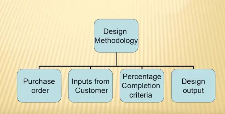
1. DESIGN METHODOLOGY:
Design Methodology is nothing but steps followed during the concept design stages of Fixture Design.
2. INPUTS FROM THE CUSTOMER:
The basic inputs from customer are as follows:
- Functional requirements
- Preferred standard components
- Car products
- Layout
- Ergo Data
- Weld Study
- Standard Detailing Templates
3. INPUTS FROM CAR PRODUCTS:
- GD&T
- Part List
- CAD Files of Car Part
- Clamp Plan
- Product Assembly Sheet
4. CLAMP PLAN:
- The clamp plan provides information on the location of pins, Rest units, clamp units, Dumps, etc.
- It is the important input from customers. The clamp plan/position should not be changed without the knowledge of customers.
- It gives the detail of the exact position of the clamping units by mentioning a coordinate in the particular position.
5. PURPOSE OF LAYOUT:
The purpose of the layout is to give information about the following:
- Flow of parts
- Station Pitch
- Robot Stations
- Accessories like tool changer and tp dresser
- Subassembly links
- Platform height
- Loading/Unloading sequence/ Heights
6. Ergo Data:
- Ergo data is the Economic refers to the study of human behavior and movements
- Ergo data provides information on loading height, .0working safety zone of the operator, etc.
7. WELD STUDY:
Weld Study involves the study of the weld gun.
Weld Study involves:
1. Weld Gun study
2. Weld Matrix and weld points
- Geo weld points
- Restart weld points
8. PERCENTAGE COMPLETION CRITERIA:
Percentage completion criteria is to check how much percentage of the design has been completed.
It also provides information on whether the work is done according to the planned schedule or not.
THESE ARE THE BASIC STAGES THAT INVOLVES IN PERCENTAGE COMPLETION:
0-25% - Input and concept design.
25-40% - Concept approval and simulation check.
40-80% -Design freezing and simulation check.
85-100% - Check and final dispatch.
9. DESIGN OUTPUT:
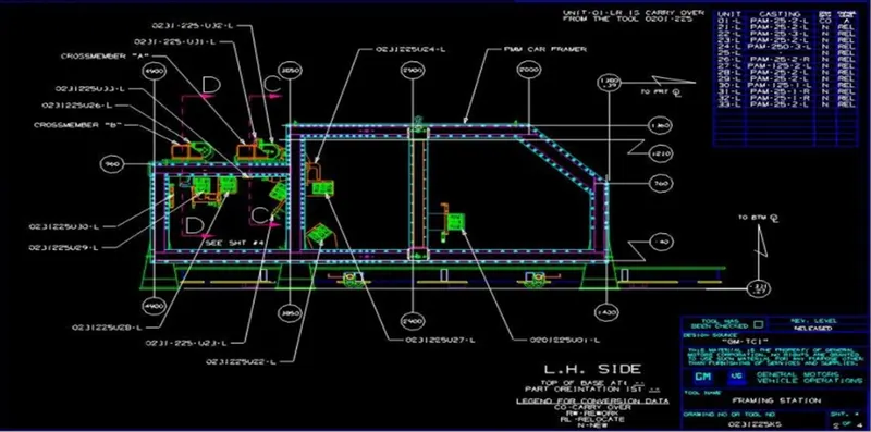
Design output involves 3D Modeling and 2D Drawings.
apart from that many documents also comes under design output,
UNUTILIZED TOOLS:
(Multiple units on a common base), require two types of a common base.
Key Sheet: An index of units and their placement on a unit base in the isometric view.
Layout Sheet: A detailed drawing of individual units to include all of their components.
NON-UNUTILIZED TOOLS:
Toos that can stand alone and can be completely detailed on a layout sheet.
10. Structuring a design tree, How does it reduce errors during the design process?:
Structuring a design tree :
A process where all the assemblies and parts are named in a specific standard.Different customers have different set of standards and the structure of design tree.
- Every company,every customer has different standards of their own structure design tree.
- So they will be giving a template on how the structuring and detailing of the design is done. And you have to follow that particular designing or structuring of the tree.
- In the design tree itself if we mentioned that particular name, wherever that part is we can easily know that this part belongs to this zone or This station or this assembly on particular unit. So this helps us to avoid errors during the design study,manufacturing assembly and inspections.
- Structuring a design tree is actually to avoid all the errors, which might come during manufacturing assembly, or either in house inspections as well.
- If the part, or assembly are not named properly, or design tree is not structured properly, it will create confusion to understand the design and may create major possibilities of making an error.
- Every part, every component should be named according to their precedures.
- If we did a mistake or renamed the entire standard parts from the customer as a design part.Now the customer is going to manufacture the entire part again from the scratch, but he already have that product in his itinerary.but extra cost,extra time and not feasible.this is also known as an error which is actually going to increase the cost of the entire assembly as well.
- Naming a fixture or a unit or a part gives the information as to which project zone or assembly do they belong.
- If we name the part properly or name the fixture properly it'll actually tell which unit or which assembly or which zone or in which station it actually belongs.
- It can help us to identify the quantity of items of same types or different types that are being used in an assembly.
11. UNITS, TYPES OF UNITS:
UNITS
In units they are two types one is unitized tools and non unitized tools.
UNITIZED TOOLS:
Unitize tools are basically tools which are a part of multiple units or multiple tools inside of itThese are the tools which has to be represented by two formats key sheet and layout sheets.unitized tools are basically two types,
- Simple units and
- Complex units.
NON UNITIZED TOOLS:
non unitized tools are basically one unit itself, which is basically don't have any process functionality to it is just to keep component on it as a stable, like grippers turntable stands, etc.
Simple Units:
Simple unit will have a very simple design to it, then the approach of the designing and manufacturing is also will be very simplistic like rest unit.
Rest Unit:
Rest unit is basically a unit where the component is tested, there is no upper clamp to it, there's no force applied to it. There is no cylinder attached to it, it's just, usually it will have a riser a blade and few rest maylers.
Fixed Pin Unit:
fixed pin unit are basically units which has a pin which is already fixed it cannot be moved.
Retract Pin Unit:
Retract pin unit are the opposite to the fixture which can be moved up and down, so it can be retracted till a certain distance.
Rough Locator Unit:
Rough locators are usually used in loading and unloading of that particular panel.
Sensor Unit:
Sensor units are used in actually sensing whether the panel or a particular component is there or not.for example If we are assembling component of nine parts or 10 parts or eight parts, they'll have that many sensors,so that every component will have different its own sensor attached to it.
Base Unit:
Basic unit where all the units has to be mounted.
Complex Units:
Complex unit, like slide unit as an example of a complex units that design in itself a little complex in design.
Slide Unit:
The slide units are basically where the sliding mechanism is involved.
Dump Unit:
Dump unit is basically like a conveyor where you keep all these panels juiced up right as for storage kind.
12 . FIXED PIN AND THEIR PERFOMANCE:
Fixed Pin Unit is a unit designed to locate the car panel using pins and below are the different parts of a fixed pin in general.
- In the Fixed unit consists of pin,pin retainer,shims,blockblade or adaptor plate and riser.
- The totally different standards so same, a pin, pin retainer blade, or a block, so here they have replaced the block with just a single blade. And this is also
- Usually in the industry they tend to use the shims which are of smaller size.that's where they're manufactured like this always preferred as much as less material as possible. That's why we design it as small with these kind of shapes.
- Retractable pin is a unit design and it is located in the car panel using pins,which has same function as the fixed pin unit, but the entire pin package part will be mounted on the retractable pneumatic cylinders.
- So this is the pneumatic cylinder which is responsible for retracting the pin. So it has also same parts up in Shims or spacers. Again with the both sides pneumatics single rod retractable cylinder and the riser.
- Usually in the industry they tend to use the shims which are of smaller size.that's where they're manufactured like this always preferred as much as less material as possible. That's why we design it as small with these kind of shapes.
13 . DIFFERENT PARTS OF A FIXED UNIT:
Shims:
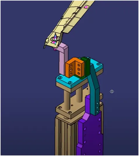
A shim is a thin and often tapered or wedged piece of material, used to fill small gaps or spaces between objects. Shims are typically used in order to support, adjust for better fit, or provide a level surface. Shims may also be used as spacers to fill gaps between parts subject to wear.
Risers:
Riser is a structure generally used to mount the toggle clamp and rest, clamp mylars and location pin.
- It is not necessary to have one riser where all the parts of clamp or rest or location units are mounted.
- Generally risers are either made of plate fabrication or plate and tube welding together or from single gas cut plate.
Blocks:
Blocks (red for representation) are versatile blocks that can be machined to any desired fixture component. Because they come as a blank block, the possibilities are endless. Adding new tap holes or grinding down to your specifications are quick and simple.
Sensor unit:
Sensor unit is a unit designed to sense the car panel by using electrical sensors, the signal from the sensor will fed to a PLC which is our programmable logic controller and sort of the next process will be executed by this signal.
14. What is the purpose of making a Rest unit & describe its parts?
Rest Unit:
Rest Unit is a unit designed to rest /Support the car panel using NC blocks/Mylar/Rest and below are the different parts of a rest unit in general.
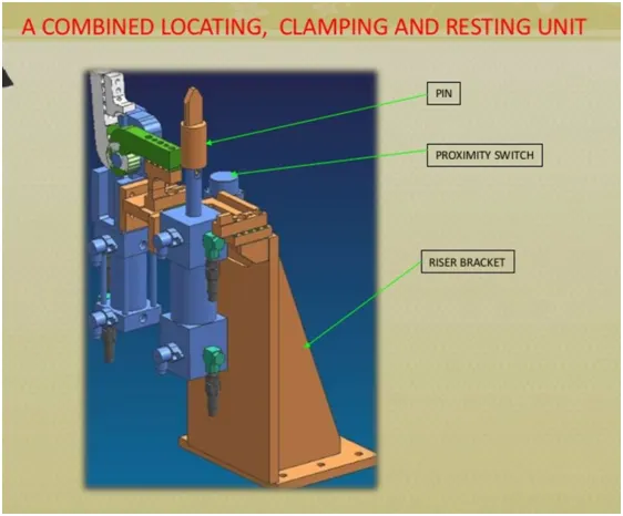
- simple unit which has a raiser and a normal blade,a spacer, which is the shims and the rest mylar.
- You can just manufacture the restaurants there and you can use the same blade as the same razor.
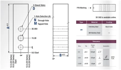
NC Block:
NC blocks (red for representation) are versatile blocks that can be machined to any desired fixture component. Because they come as a blank block, the possibilities are endless. Adding new tap holes or grinding down to your specifications are quick and simple.
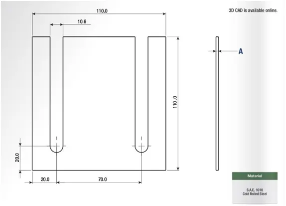
Shim:
A shim is a thin and often tapered or wedged piece of material, used to fill small gaps or spaces between objects. Shims are typically used in order to support, adjust for better fit, or provide a level surface. Shims may also be used as spacers to fill gaps between parts subject to wear.
Risers:
Riser is a structure generally used to mount the toggle clamp and rest, clamp mylars and location pin.
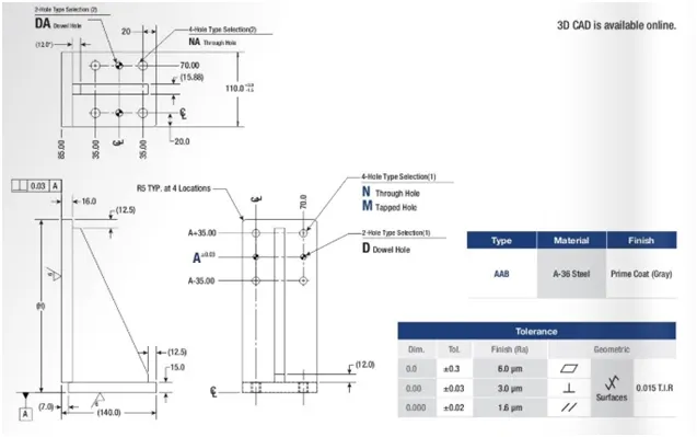
- It is not necessary to have one riser where all the parts of clamp or rest or location units are mounted.
- Generally risers are either made of plate fabrication or plate and tube welding together or from single gas cut plate.
15.What are the basic fundamentals to design a Sensor unit?
Sensor unit:
Sensor unit is a unit designed to sense the car panel by using electrical sensors, the signal from the sensor will fed to a PLC which is our programmable logic controller and sort of the next process will be executed by this signal.
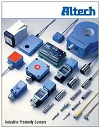
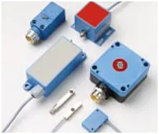
- So our sensors are basically used to sense the particular car panel. Now, the signal which gets from this sensor will be fed to the PLC, the PLC will decide whether the signal from the component or the assembly actually has the particular car panel or not.
- If it does not have it will not execute the next process, and it will stop the entire process that itself until the panel is loaded.
Fundamentals of Sensor Unit Design:
Every single Loose panel, which are being welded in a tool should be sensed.
So every single panel that we are going to assemble in that particular panel.
For example:
- If we are using nine different panels to assemble in one panel. Every single one of those panels should have one sensor attached to it.
- Each panel should be sensed by one or two sensors depending on the size of the panel prefered to be in diagonally opposite ends of the panel.
- If a component is really small,We don't have to use two or three sensors for that you can just use one sensor, which will detect that particular panel.
- If the panel is really big. we will use two sensors towards the opposite directions of each to sense their particular panel.
- So every sensor should be mounted in three directional adjustable ways in general.
- Sensors Detect in Three Different Movements in that first one is upward and downward movement of the sensor.The second one is from left and right movement, and direction so all three directions.
Sensor manufacturers is IFM,Pepperl-Fuchs and Omron, etc.
Types of Sensors Used In General
Proximity sensor :
proximity sensor is used in cell phones as well to detect a particular component. So, proximity sensors are range from 5 to 6 mm to 8 to 10 mm.
laser sensors:
Laser sensors are used for bigger sensing the distance.if the component cannot be near the panel. It has to be farther away from the panel, then you will be using laser sensor.
Photo Electric Sensor:
Photo electric sensors this is basically a proximity sensor and this can be utilized as a laser centered sensor and this is an example of a photoelectric sensor.
16.What is a Rough locator unit & what are the basic fundamentals to consider while designing it?
Rough locator :
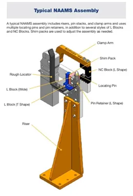
Rough locator is a part which is designed to guide the operator to locate the car panel on the pin accordingly rough locator can be of standard parts or make part.
The locators are used in loading and unloading the pan. These are very handy while orienting the part properly, so it will actually guide the entire the operator to load the panel in a particular orientation.
Fundamentals Of Rough Locator Design
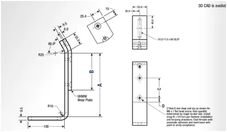
- Rough Locator should be placed at the edge of the component or car panel,which has to be guided.
- So these are four carriers has to be placed at the edge.These are the edges of the entire panel, where the rough locators are the locating pins. So by these locating pins, you can either restrict the movement of the entire panel as well so placed in the same angle of the car panel edge with a minimum distance of 2 to 5 mm from the edge of the car panel .
- Rough Loacators should not touch the car panel,so that it should not damage the panel by loading and unloading.
- Rough locator should be designed in such a way that the panel will come from top to bottom and then it will be guided in the same direction.
- Rough Locators cannot be in just one angle it should be at the angle where the panel edge is supposed to be.
- Rough locator should start guiding the panel before 10 to 15 mm to the start of the pin engagement is one of the important parameters to consider.
- Rough locators should start guiding the panel downwards, before even the pin unit, engage in the panel.
- Rough Locators should be designed with entry angle for car part entry.
- Rough locators should be designed with two slots to mount for easy adjustments.
- The slots should be in the direction of car part guiding.
17.What is a Base unit and describe it's parts?
Base unit:
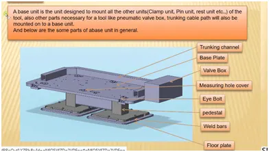
The base unit is a unit designed to mount all the other units like time unit,pin unit , etc. of the tools and also other parts necessary of the tool of pneumatic valve box,trunking cable path will also be mounted on the base unit.
- All the units are basically like clamp unit,pin unit,rest unit And the Rough locators, everything will be mounted on the base unit.
Valve box:
A valve box is basically a box which supplies air to all the other pneumatic cylinders. it's it's a device which includes a lot of other solenoid valves, so it will have one inlet and one outlet and from that one inlet, all the other solenoid valves will be attached to it. And each solenoid valves will have the input, and then again supplied to the separate cylinder, then again the output will be collected, while this solenoid valves, and again given back to the valve box.
Measuring hole covers:
Measuring Hole covers is on the base unit which is for measuring purpose.
Eye Bolt:
It is to drag the entire unit and relocated.
Pedestal :
By this pedestal is for standing the entire unit.
Weld Bars and floor plates:
Weld bars are to mount it to the floor.
18.What is a Dump Unit and what are its functions?
Dump unit :
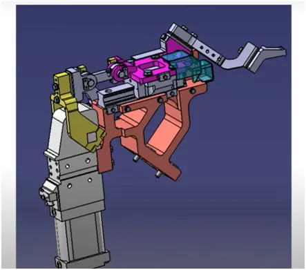
A dump unit is a unit where you actually assemble a component which if you have certain constraints.
Functions Of Dump Unit:
if you have particular constraint and you cannot assemble in a normal way to use this use it in different ways again it has same dumb cylinder and and it has open position and closed position.and it has Clamp Cylinder Unit too.
That is why this are very complex and design.:
if you have any geometrical constraints, you can use this dampener to constrain your components.
19. What is a Slide unit? Mention where Slide units are commonly used.
Sliding units :
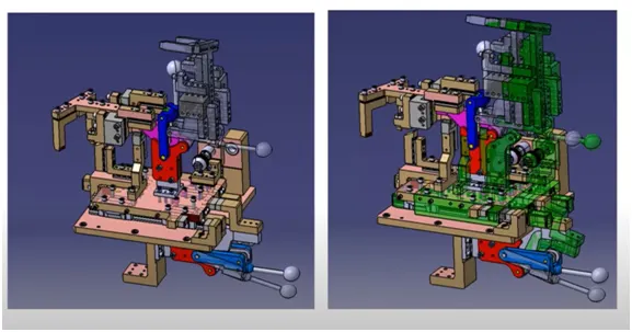
Sliding units are basically used in places where you have a lot of constraints or space constraints, when you cannot use different types of units to design the entire assembly. So, here you will use this sliding Only
Sliding cylinder:
The sliding cylinder has One open position and One closed position, which has to guide rails direction to the entire panel is going to move.
position locking unit :
The position locking unit which will lock the position at that particular point doesn't allow the entire plate to move.
Sensor Unit :
Sensors need to sense whether this entire component has reached here or not.
Stopper blocks :
Stopper blocks as I said initially to control the entire panel moving and it's a moving part.