Week 2 - Converging diverging nozzle
In this project, I will be simulating a simple convergent-divergent nozzle in ANSYS Fluent. The geometry is split into half, since the entire nozzle is symmetrical. These are the dimensions of the nozzle:
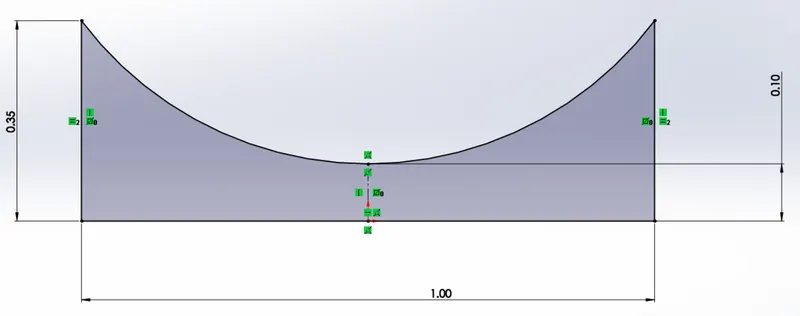 Geometry
The geometry can be created in SpaceClaim using lines and an arc with 3 points.
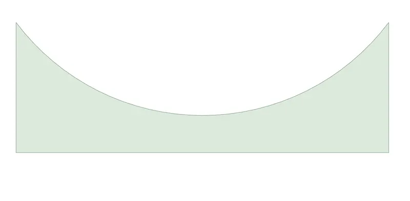
This is the completed geometry in SpaceClaim:
Meshing
The default mesh was used, with an element size of 0.01m.
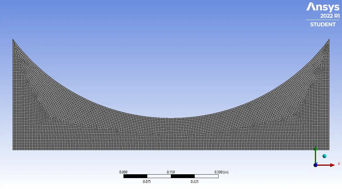
The mesh contains 7263 nodes and 6991 elements.
Mesh Metrics
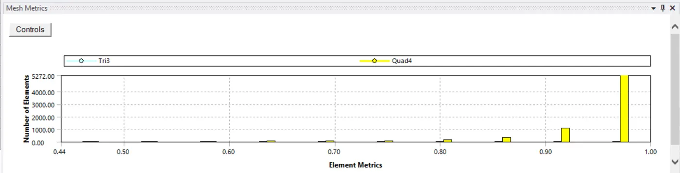
Most of the elements have a quality greater than 0.9, this indicates the mesh quality is satisfactory for this case.
Simulation Setup
General
The simulation used a density-based, steady state and axisymmetric solver.
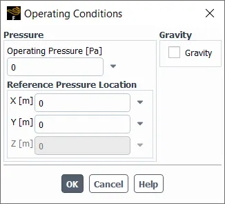
Operating Conditions
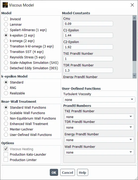
Turbulence Model
The turbulence model used was k-epsilon with standard wall treatment with energy checked.
Boundaries
inlet: pressure-inlet with a gauge pressure and initial gauge pressure as 101325 Pa (1 atm), and a temperature of 300K.
outlet: pressure-outlet with a gauge pressure of 2735.775 Pa.
axis: symmetry boundary condition.
wall: wall boundary condition.
Intialisation and Calculation
This setup was hybrid initialised and calculated for 500 iterations.
3 contours were used, to monitor the solution during calculation. They were Pressure, Temperature and Velocity across the domain.
Results
Temperature Contour
This was taken in Fluent.
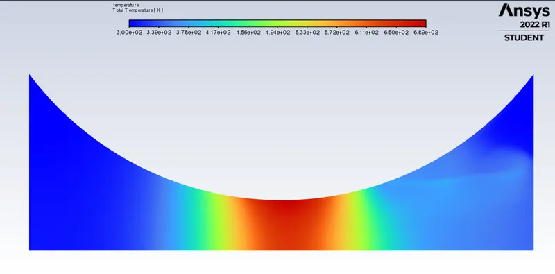
This variation in temperature is expected, since the inlet air is constricted through a small opening, this initially causes the air to increase in temperature. During expansion, the reverse is seen.
Pressure Contour
This was taken in CFD-Post.
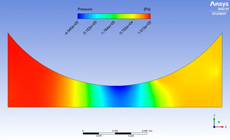
As air enters the converging part of the nozzle, the velocity increases rapidly and as a result, the pressure of the air around the throat reduces to the lowest in the entire domain. After expansion, pressure increases slightly but not as near the inlet.
Velocity Contour
This was taken in CFD-Post.
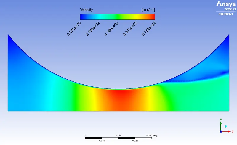
The velocity increases rapidly due to constriction of the flow, the maximum velocity is seen at the throat of the nozzle. The maximum velocity is about 2.5 times the speed of sound. This is in agreement with the volumetric flow equation. (V*A = constant) As the area decreases near the throat, the velocity increases to keep the product of area and velocity constant.
Mach Number across the domain
This was taken in CFD-Post.
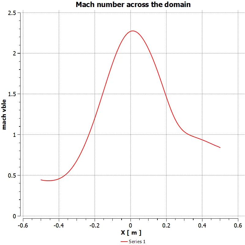
The chart shows the variation of mach number throughout the axis of the nozzle (or symmetry axis), the mach number cross 1 around 0.25m from the inlet of the nozzle.