Week 2 Challenge
Compare Four different tyoes of Fuel cells andstate their applications
| FUEL CELL TYPE | COMMON ELECTROLYTE | OPERATING TEMPERATURE | TYPICAL STACK SIZE | ELECTRICAL EFFICIENCY (LHV) | APPLICATIONS | Advantages | CHALLENGES | |
| Polymer electrolyte membrane (PEM) | Perfluorosulfonic acid | <120°C | <1 kW–100 kW | 60% direct H2; a 40% reformed fuel b |
Backup power Portable power Distributed generation Transportation Specialty vehicles |
Solid electrolyte reduces corrosion and electrolyte management problems Low temperature Quick start-up and load following |
Expensive catalysts Sensitive to fuel impurities |
|
| Alkaline (AFC) | Aqueous potassium hydroxide soaked in a porous matrix, or alkaline polymer membrane | <100°C | 1–100 kW |
|
Military Space Backup power Transportation |
Wider range of stable materials allows lower cost components Low temperature Quick start-up |
Sensitive to CO2 in fuel and air Electrolyte management (aqueous) Electrolyte conductivity (polymer) |
|
| Phosphoric acid (PAFC) | Phosphoric acid soaked in a porous matrix or imbibed in a polymer membrane | 150°–200°C |
5–400 kW, 100 kW module (liquid PAFC) <10 kW (polymer membrane) |
40% | Distributed generation |
Suitable for CHP Increased tolerance to fuel impurities |
Expensive catalysts Long start-up time Sulfur sensitivity |
|
| Molten carbonate (MCFC) | Molten lithium, sodium, and/or potassium carbonates, soaked in a porous matrix | 600°–700°C | 300 kW–3 MW, 300 kW module |
50% |
Electric utility Distributed generation |
High efficiency Fuel flexibility Suitable for CHP Hybrid/gas turbine cycle |
High temperature corrosion and breakdown of cell components Long start-up time Low power density |
2.
Using a plot with energy density on the X axis and power density on the Y axis, arrange various battery types like lithium ion, lead acid, Nickel Cadmium, Ultracapacitor, fuel cell.
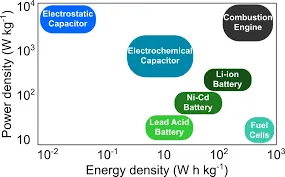
Figure 1 Representation of a battery (Daniell cell) showing the key features of battery operation and the requirements on electron and ion conduction.
Figure 2 Representation of (A, top) an electrochemical capacitor (supercapacitor), illustrating the energy storage in the electric double layers at the electrode−electrolyte interfaces, and (B, bottom) a fuel cell showing the continuous supply of reactants (hydrogen at the anode and oxygen at the cathode) and redox reactions in the cell.