Week -2
- Make a Simulink model of Doorbell using solenoid block with the following details:
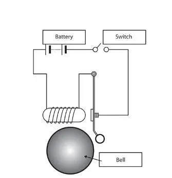
In the above arrangement, when the switch is closed the electromagnet receives electrical power from the battery and pulls the metal arm to hit the bell producing sound. Create a situation where the switch is closed for 2 seconds and then released. Observe the physical movement of the plunger.
Simulink Model
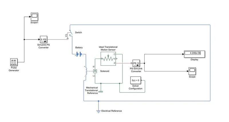
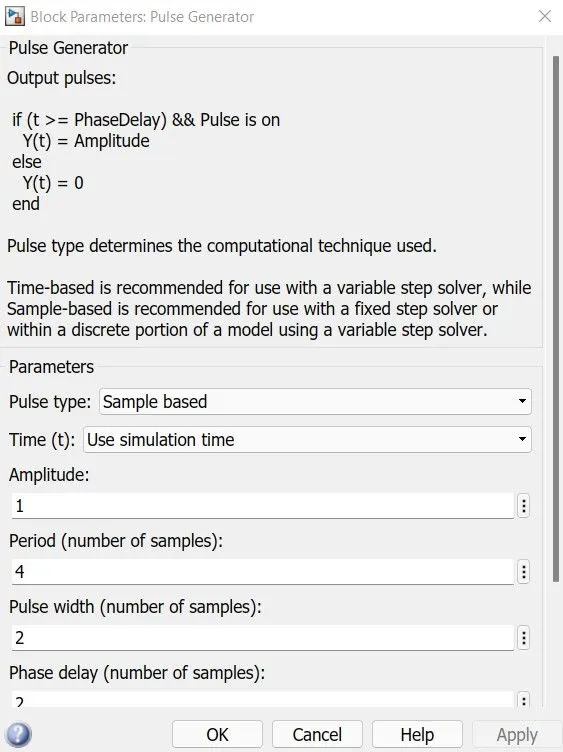
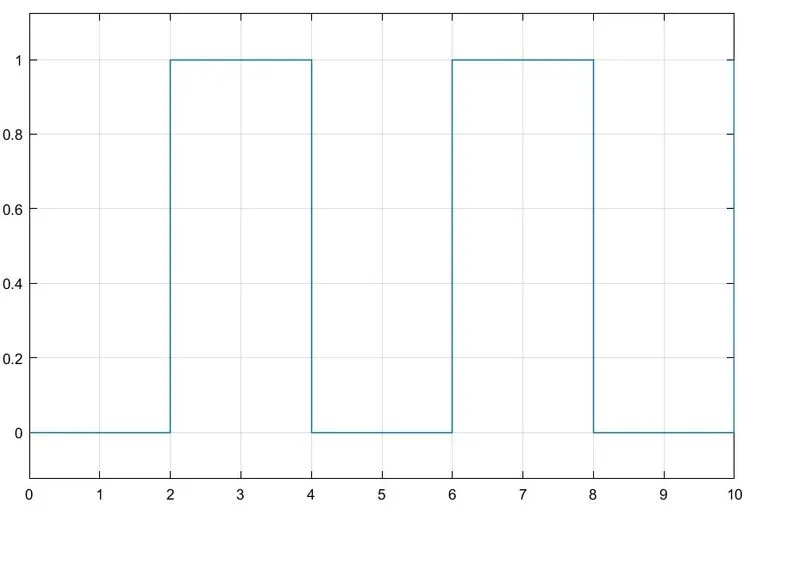
Here the Pulse Generator block is used to generate a sqaure wave signal. Pulse width is given 2 to produce a pulse after 2 seconds. Because of this the switch will close for 2 seconds only. A Simulink-PS converter block is used to convert the simulink signal into physical signals. The signal is then fed into the switch block. A battery block is used in this simulation as a power supply. One end of the battery block is connected to the switch block.
A solenoid is a long piece of wire which is wound in the shape of a coil. When the electric current passes through the coil it creates a relatively uniform magnetic field inside the coil. The solenoid can create a magnetic field from electric current and this magnetic field can be used to generate a linear motion with the help of a metal core. This simple device can be used as an electromagnet.
We used a solenoid block in this model. One end is attached to the battery and the other end to the switch block. C and R are both Mechanical Translational Conserving Port. The Ideal Translational Motion Sensor block converts an across variable measured between two mechanical translational nodes into a control signal proportional to velocity or position. It is used to observe the movement of the plunger. Solenoids C and R ports are connected with respective ports of the motion sensor. The P port generates a physical signal which we need to convert into simulink signal by using PS-Simulink Converter. A solver configuration block is connected in the circuit. It specifies the solver parameters that your model needs before you can begin simulation. An Electrical reference block is connected in between the solenoid and the switch which acts as a earthing terminal for the battery. A Mechanical translational reference block represents a mechanical translational reference point that is a frame or a ground. Use it to connect mechanical translational ports that are rigidly affixed to the frame (ground).
Results
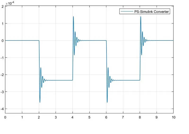
Here the x axis represent Time and y axis represent position of the plunger. We can see that after 2 seconds there is a movement in the plunger. It remains in that position for 2 seconds after that it moves to another position.
2. Use a thermistor to sense the temperature of a heater & turn on or turn off the fan as per the below conditions:
Temperature source: 20 °C from 0 to 10 seconds, 27 °C from 10 to 30 seconds, 23 °C from 30 to 50 seconds
Fan conditions: ON if the temperature above 25 °C, OFF otherwise
Simulink Model
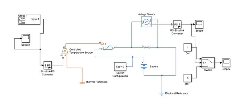
A thermistor (or thermal resistor) is defined as a type of resistor whose electrical resistance varies with changes in temperature. Although all resistors’ resistance will fluctuate slightly with temperature, thermistor is particularly sensitive to temperature changes.
Results
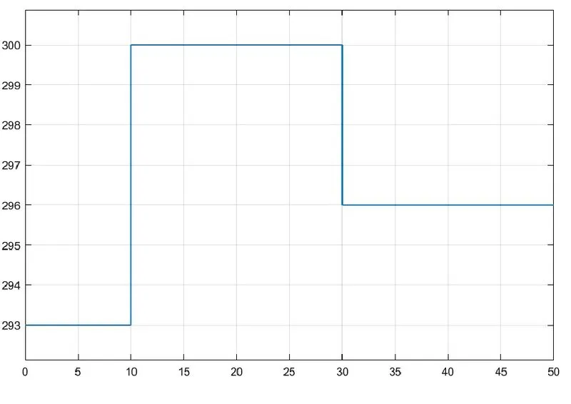
Here we have used a signal builder block to generate a temperature signal which varies with time as mentioned above. To get the plot of the signal we used a scope block.
A Simulink-PS converter block is used to convert the simulink signals into physical signals. A controlled temperature source block is used next in the model this block represents the heater or an ideal energy source in a thermal network that can maintain a controlled temperature difference regardless of the heat flow rate. A port of the controlled temperature source is connected with a Thermal reference block. This block represents reference point in a thermal network where temperature is equal to absolute zero. In the next circuit a thermistor, resistor and battery blocks are used. Positive terminal of the battery is connected with the positive terminal of the thermistor and the negative terminal of the resistor is connected with negative terminal of the battery. A solver configuration is attached in the circuit to define solver for the simulation. The electrical reference block acts as an earthing for the simulation. A voltage sensor is attached parallelly with resistor to get the voltage difference across the resistor. Now if we run the simulation and plot the voltage output from the sensor, we get this
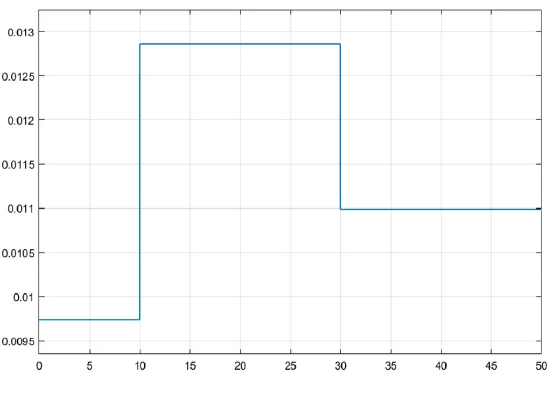
We can see here at first 10 seconds the voltage was between 0.0095 to 0.01 , after 10 to 30 seconds it was between 0.0125 and 0.013 and for 30 to 50 seconds the value is 0.011. The fan would only rotate if the temperature goes above 25°C. So to rotate the fan the voltage needs to be in between 0.0125 to 0.013. Now we use a switch block to set the required conditions. It has three nodes one node is connected with the voltahe output of the voltage sensor. Other two connected with two constant blocks. We set the values as 1 when the fan is on and 0 when the fan is off. The threshold value of the switch is set at 0.012 so when the voltage reaches this point, it triggers the switch. Now if we run the simulation and plot the data we get the above result.
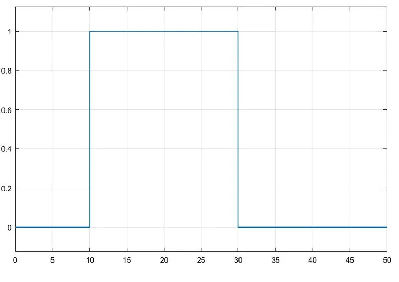
We can see here when the temperature is above 25°C according to the previous plots between 10 seconds to 30 seconds the signal output is 1 or the Fan is ON.