Week 8 - Challenge 1 - Base Bracket Design
BASE BRACKET
Class A Surface - It is an asthetic surface made by automotive designer. It is the outer most surface.
Class B Surface - It is the surface below Class A Surface. This is the surface that contains engineering aspects of a model.
Class C Surface - It is the surface that is created by joining Class A and Class B surface.
Tooling Axis
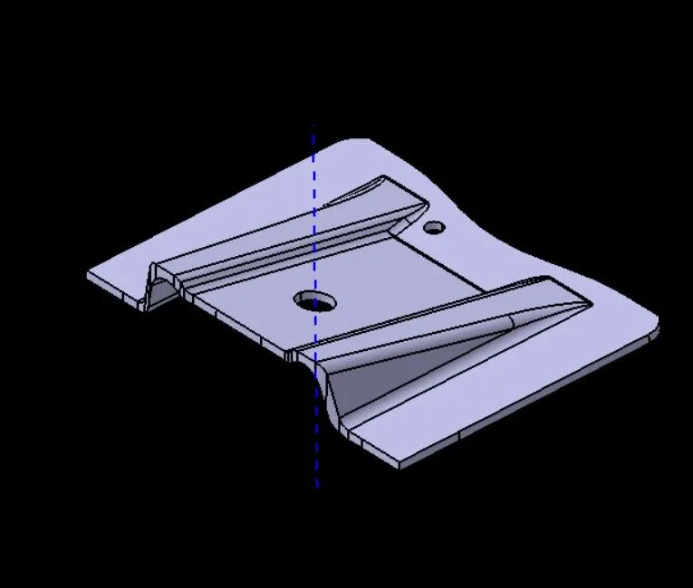
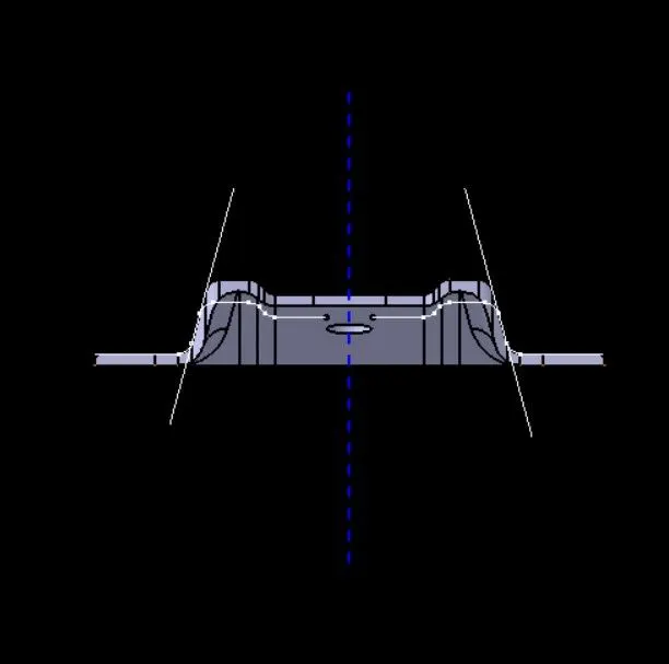
The direction in which the mould open and closes is the tooling axis. There are several ways to create a tooling axis, one of the methods is the Bisection method, where the line is created by bisecting the other lines and the point. We first have to check if theres any gap remains in the surface boundery. A flat surface or hole is good choice for selecting the tooling axis. First intersect command is used to create the boundary in xz plane. then we draw two lines on the drafted face. By using bisecting line command we create a tooling axis in x direction.
Draft Analysis
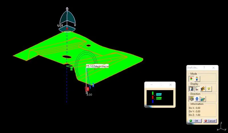
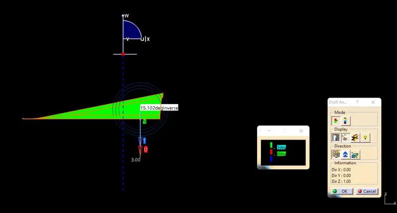
The Draft Analysis command enables you to detect if the part you drafted will be easily removed. This type of analysis is performed based on color ranges identifying zones on the analyzed element where the deviation from the draft direction at any point, corresponds to specified values.
Class A Surface
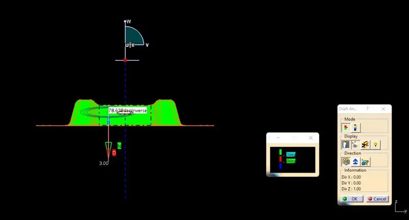
Final plastic component
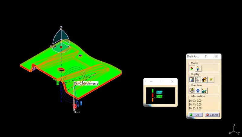
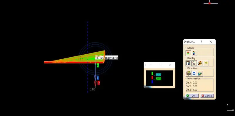
For draft analysis first we have to select the view mode to material. Then we have to open the featured draft analysis tool box. Then aligning the compass sign with the tooling axis and click on the lock sign. After that we have to click on a surface. Then the surface will turn into green. 3 degree draft value should be given as it is the permissible draft value.