Week 8 - Challenge 6 - Core & Cavity Design
Switch Bezel Core and Cavity design
Class A surface - This is a surface created by an automotive designer. It is used for asthetic purpose.
Class B surface - This surface contains all the supporting features like ribs.This is created by offsetting the Class A surface.
Class C surface - This is a surface created by joining the Class A and Class B surface together.
Core and Cavity
The core and cavity are the two halves of the mold where the hot molten plastic material is injected into the core and cavity and the gap between the core and cavity is filled with the hot molten material during the injection moulding process and then hardened into the final shape. The mold design of the core and cavity is critical to the proper molding of the product. The core is the raised part of the mold and the cavity is the recessed part of the mold. The cavity and core in a typical plastic injection molding machine of an injection mold are the molding parts of the mold and play a key role in the shape of the molded part.
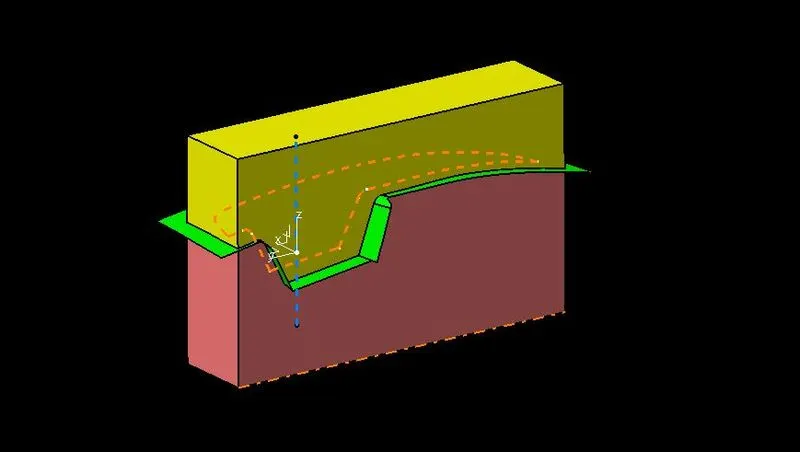
Core
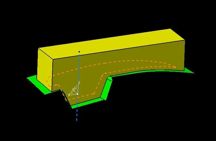
Cavity
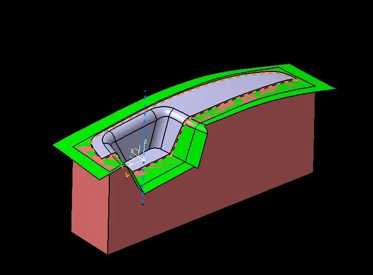
Parting Surface and Parting Line
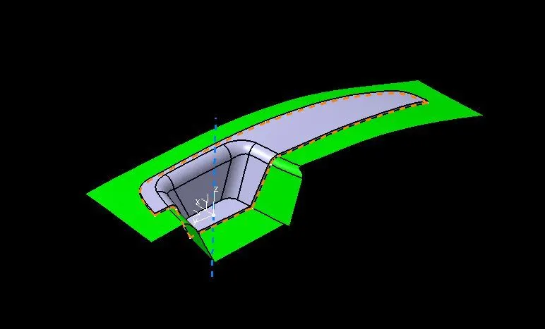
A parting line in the industrial casting of molds,is the border line in which draft angles change direction. One can check the parting line in the mould or product which divides the two half, the core and the cavity of a molded part. It is sometimes a starting point for the mold parting surface.
The parting surface is the surface of the mold that is perpendicular to the parting line. The purpose of the parting line is to separate the two halves of the mold so that the molded part can be ejected by the ejector pin.
In the above image the green coloured surface is the parting surface and the orange coloured dotted line is the parting line.
Tooling Axis
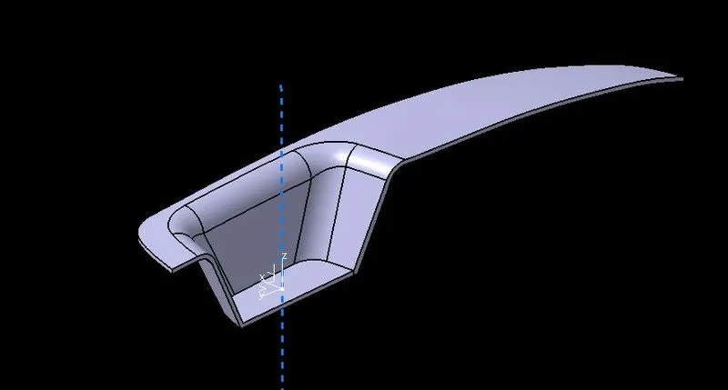
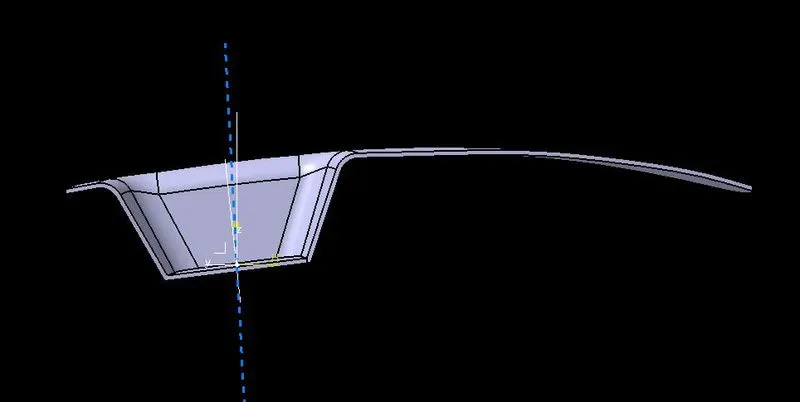
First, the given styling surface is checked for any irregularities and if found any then it is corrected by using Trim, Extrapolate, Split and Join commands. Tooling axis is the The direction in which the mold or core and cavity opens. 3 degree draft is also required for easy removal of the material from the mould. A plane flat surface is perfect location for tooling axis. First we create a reference point on base surface of the object. Then we draw a line in the z direction. Two inclined lines are drawn in the wall of the switch bezel. Then a bisecting line from them is created. On xz plane we only have one surface available so a line from centre point is drawn and provided with an inclination of 6 degrees from the surface. Bisecting the two lines will give us the tooling axis.
Draft Analysis
Class A Surface
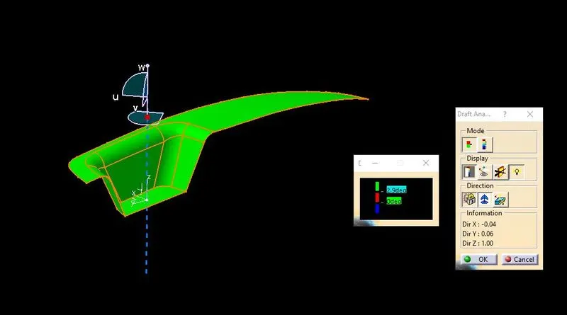
Final component
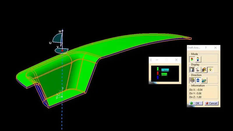
The draft analysis technique is used to analyze whether our part model created in CAD is manufacturable based on the draft condition applied. Here the part should get easily removed from the Mold (in case of plastic).
No parts can be ejected from the tool if it is having a straight 90-degree profile from its base surface. A small draft angle is provided to each and every area of the component in order to get easy removal of the component from the tool.
Here we are providing a direction in which components should eject in order to get easy removal of components from the tool. In other words, it also lets us know whether the model is having a draft angle and how much is the draft angle from the tool direction. First we change the view mode to custom view parameter's Material mode then the feature draft analysis is enabled. Then the compass was activated and placed with the tooling axis. After that by selecting the quick analysis mode, the recommended value is 3 degrees and checked for the component's draft angle.