Week 9 - Project 1 - Door Trim Lower with Engineering Features
Door Trim Lower with Engineering Features
Class A surface - This is a surface created by an automotive designer. It is used for asthetic purpose.
Class B surface - This surface contains all the supporting features like ribs.This is created by offsetting the Class A surface.
Class C surface - This is a surface created by joining the Class A and Class B surface together.
Tooling Axis
First, the given styling surface is checked for any irregularities and if found any then it is corrected by using Trim, Extrapolate, Split and Join commands. Tooling axis is the The direction in which the mold or core and cavity opens. 3 degree draft is also required for easy removal of the material from the mould. A plane flat surface is perfect location for tooling axis. To make the Draft Analysis easier, it will be better if the line is created from the CG point. For that, we need to select the measure inertia option from the measuring toolbar.
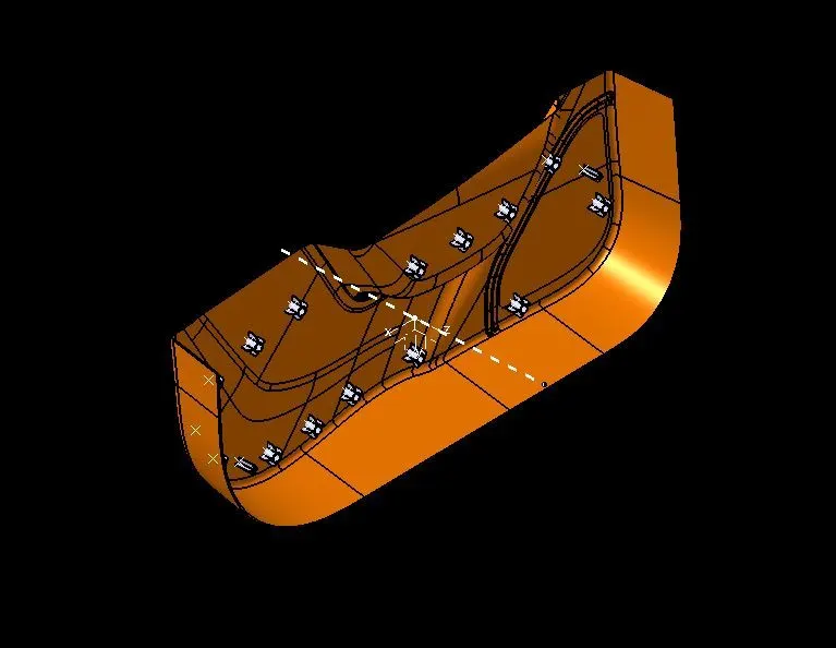
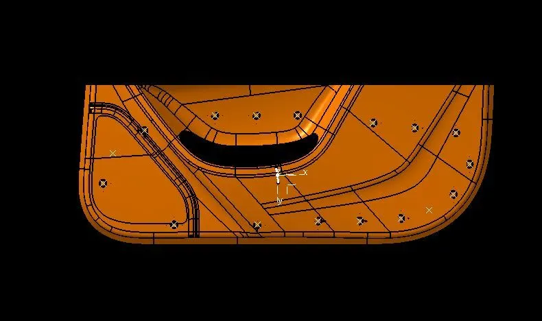
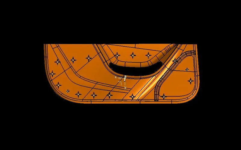
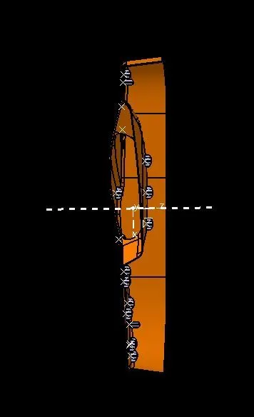
Draft Analysis
The draft analysis technique is used to analyze whether our part model created in CAD is manufacturable based on the draft condition applied. Here the part should get easily removed from the Mold (in case of plastic).
No parts can be ejected from the tool if it is having a straight 90-degree profile from its base surface. A small draft angle is provided to each and every area of the component in order to get easy removal of the component from the tool.
Here we are providing a direction in which components should eject in order to get easy removal of components from the tool. In other words, it also lets us know whether the model is having a draft angle and how much is the draft angle from the tool direction. First we change the view mode to custom view parameter's Material mode then the feature draft analysis is enabled. Then the compass was activated and placed with the tooling axis. After that by selecting the quick analysis mode, the recommended value is 3 degrees and checked for the component's draft angle.
Class A surface
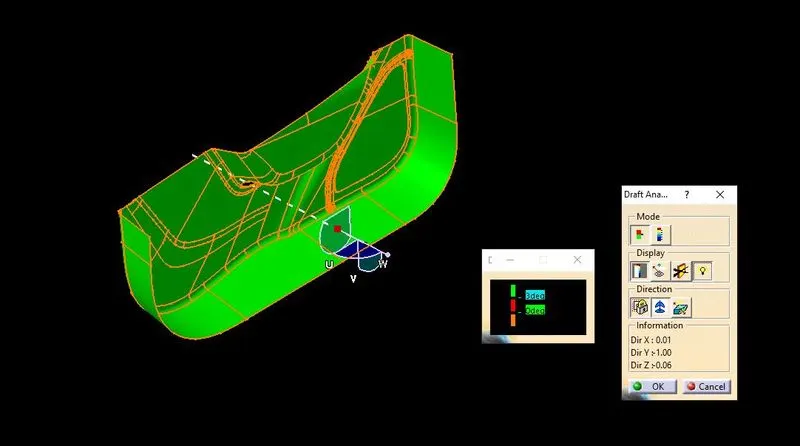
Full Component
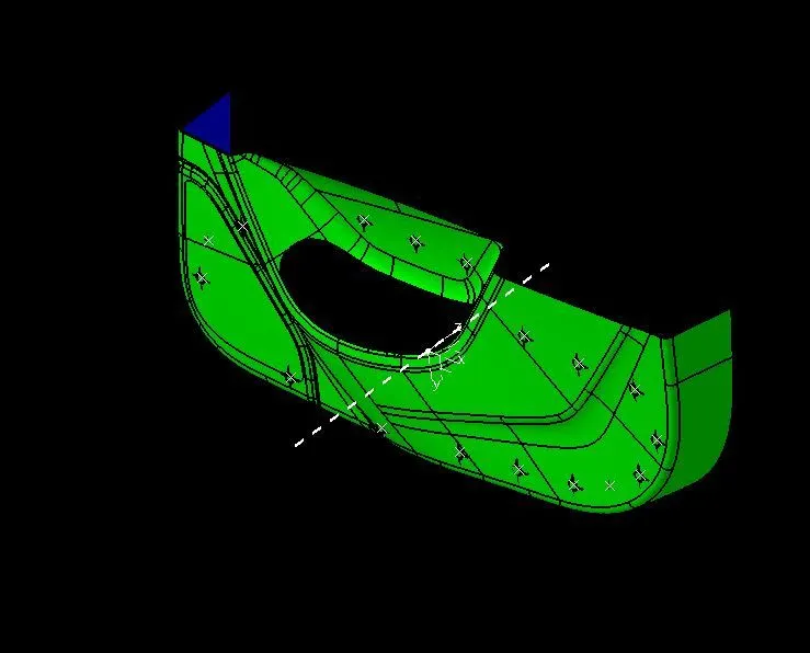
Engineering Features
Locator
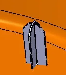
Locators are used to positioned the component in exact location and act as a guide for joining the two component. There are mainly two type of locator four way and two way locator.
Heat stake
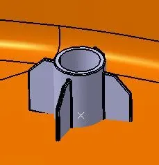
Thermal staking is an assembly method that uses the controlled melting and reforming of a plastic stud or boss to capture or lock another plastic or metal component of an assembly in place. Heat stakes is used to arrest the degree of freedom of locators by 3-2-1 principle in automotive tooling design.