Project
Carry out a system-level simulation of an all-terrain vehicle.
An all-terrain vehicle (ATV) is defined as a motorized off-highway vehicle designed to travel on four low-pressure or non-pneumatic tires.The rider sits on and operates these vehicles like a motorcycle, but the extra wheels give more stability at slower speeds. As the name indicates, an ATV is designed to handle a broader variety of terrain than regular vehicles.
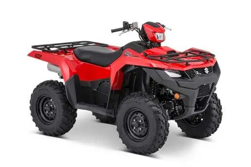
We will simulate the ATV operations in 3 different models.
a. Simulink model without dashboard
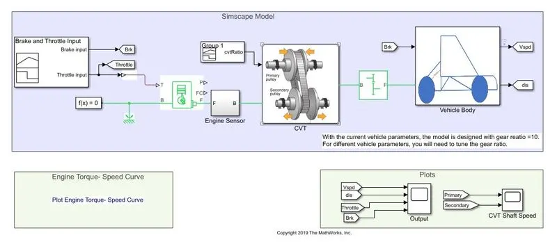
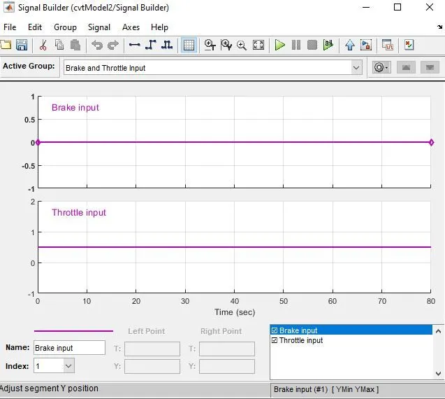
In this model we use a signal builder block, Generic engine block, Engine sensor, Simple gear block for the gear ratio and two subsystem blocks (CVT and Vehicle body). In the model throttle and brake inputs are given. The brake inputs are given zero so there's no brake being applied during 80 seconds. The throttle is also constant for 80 seconds.
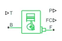
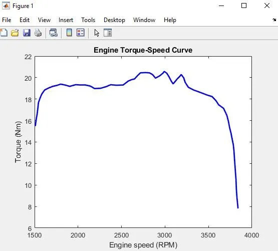
The Generic Engine block represents a general internal combustion engine. This block is a suitable generic engine for spark-ignition and diesel. Speed-power and speed-torque parameterizations are provided. A throttle physical signal input specifies the normalized engine torque. Optional dynamic parameters include crankshaft inertia and response time lag. A physical signal port outputs the engine fuel consumption rate based on the fuel consumption model that you choose. Optional speed and redline controllers prevent engine stall and enable cruise control.

The Simple Gear block represents a gearbox that constrains the connected driveline axes of the base gear, B, and the follower gear, F, to corotate with a fixed ratio that you specify. You choose whether the follower axis rotates in the same or opposite direction as the base axis. If they rotate in the same direction, the angular velocity of the follower and the angular velocity of the base have the same sign. If they rotate in opposite directions, ωF and ωB have opposite signs. You can easily add and remove backlash, faults, and thermal effects.
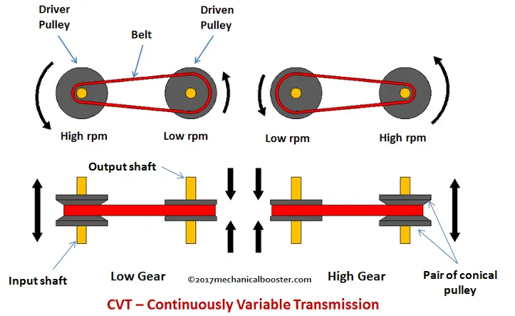
While a traditional transmission uses a wide variety of intricate parts to shift between a range of preset gears, most CVT systems work through a pulley system. In short, this system consists of cones at each pulley connected via a chain belt. The cones can move to increase or decrease the belt diameter to change gear ratios, allow for quick shifting into the needed ratio for increased power, and boost fuel economy. One pulley in the CVT is connected to the engine and the other directs power to the wheels. The width of these pulleys changes based on the needed power; as one gets larger, the other gets smaller. This allows a CVT to deliver strong and seamless acceleration.
Below CVT subsystem block has two ideal motion sensor blocks, a variable ratio gear block, input shaft inertia and output shaft inertia blocks.
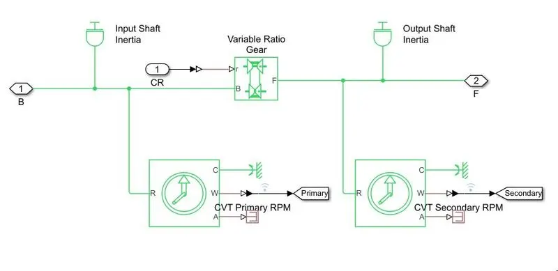

The Variable Ratio Transmission block represents a gearbox that dynamically transfers motion and torque between the two connected driveshaft axes, the base and the follower.

The Ideal Rotational Motion Sensor block represents an ideal mechanical rotational motion sensor, that is, a device that converts an across variable measured between two mechanical rotational nodes into a control signal proportional to angular velocity or angle. Connections R and C are mechanical rotational conserving ports that connect the block to the nodes whose motion is being monitored. Connections W and A are physical signal output ports for velocity and angular displacement, respectively.
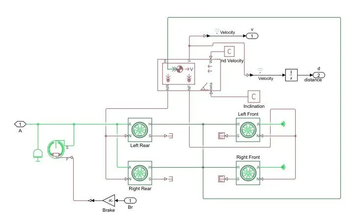
Above Vehicle body subsystem block has four tyre blocks, one vehicle body body block, one intertia output shaft block and one double drum brake block.
Results
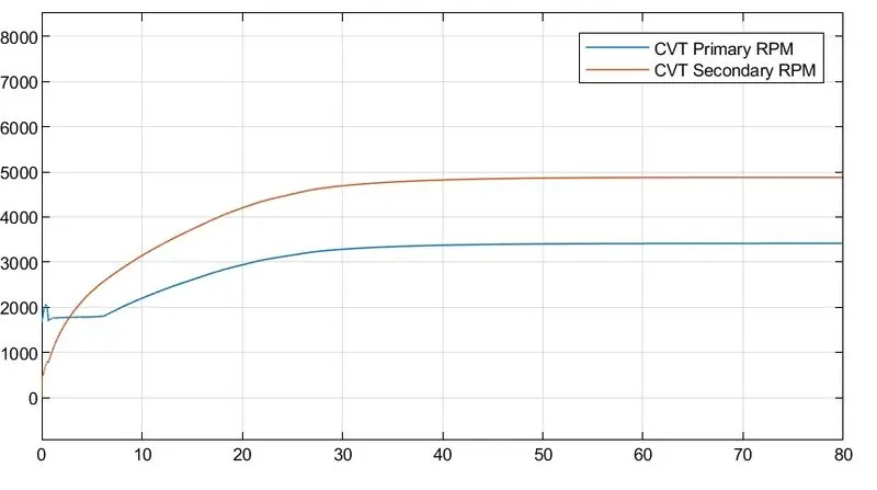
This plot shows the difference in angular velocities of two shafts of the variable ratio gear system.
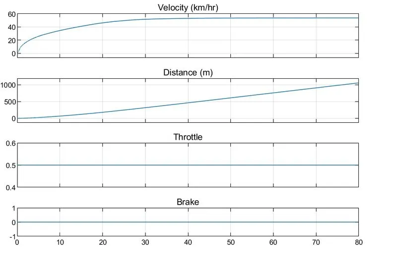
This plot shows that after 40 seconds the vehicle has travelled 500 meters distance and reached a velocity of more than 40 km/hour.
b. Simulink model with dashboard
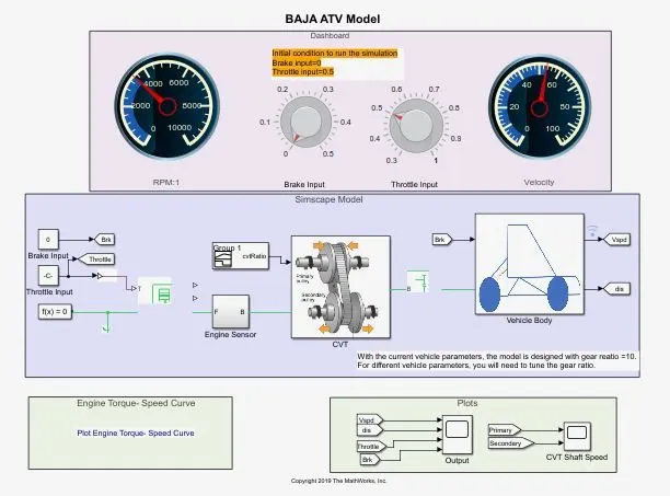
In this model we have two knobs which provides variable brake and throttle input. Two dashboards are also provided to see the real time output data.
Results
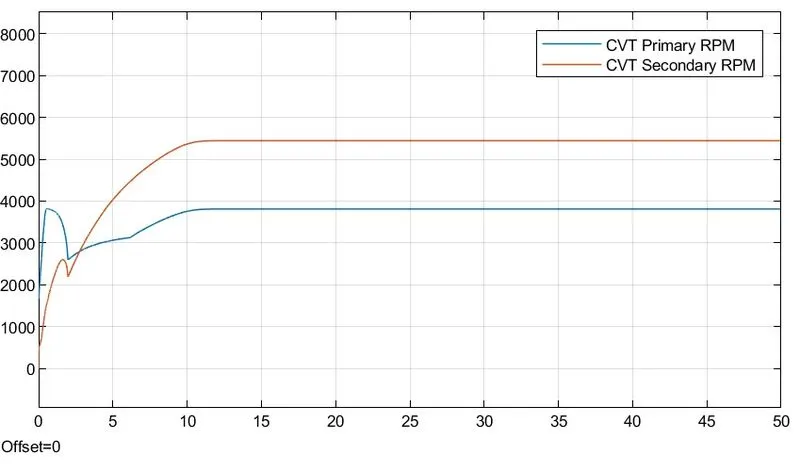
Angular velocity of two different shafts of variable ratio gear block.
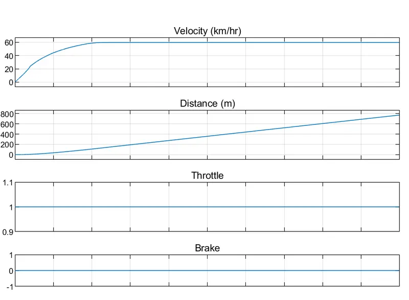
Velocity and distance covered by the vehicle.
c. Simulink model of ATV using look up table
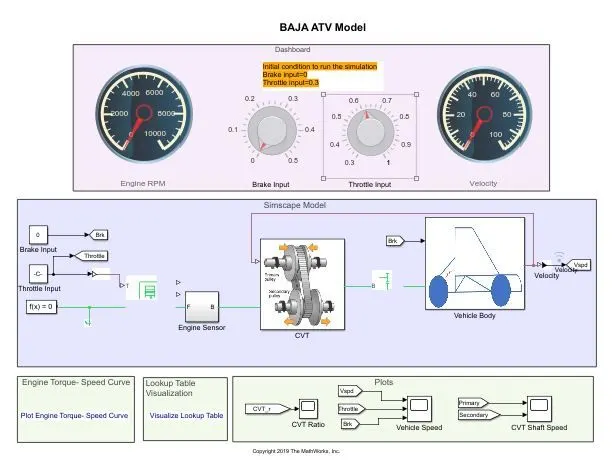
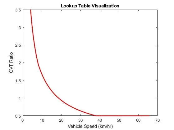
In this table variable gear ratios are provided by using a look up table. A lookup table block uses an array of data to map input values to output values, approximating a mathematical function.
Results
CVT ratio plot
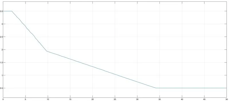
Vehicle speed plot
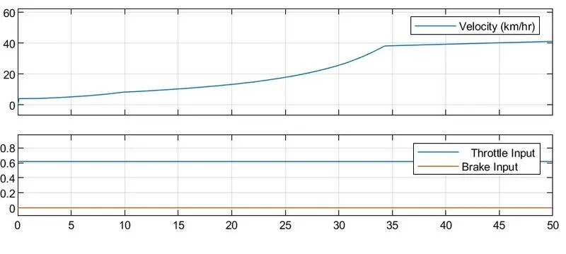
Vehicle velocity is increasing in first 35 seconds it reaches 35 km/hr. Then it is nearly constant for next 50 seconds.
CVT shaft speed plot
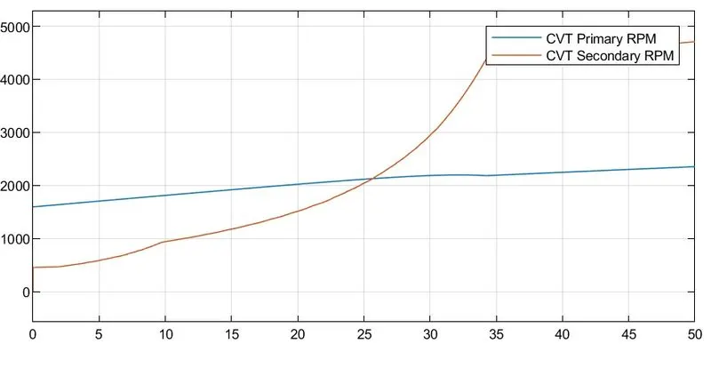
Like these models we can replicate different driving conditions for a ATV and we can simulate the real outputs before manufacturing it.