Simulation of Flow through a pipe in OpenFoam
AIM
To simulate an axi-symmetric flow by applying the wedge boundary condition in openfoam.
THEORY
Here, a pipe of diameter of 20mm is considered. The flow is assumed as laminar and flows through a constant cross-section pipe at an inlet Reynold's number of 2100. Fluid is considered as water. Density of water = 1000 `(kg)/m^3`, and dynamic viscosity `mu` = 8.9x`10^-4`Pa.s . Since we assume Re = 2100, it means that the flow will be laminar.
Entry length is given by the formula `L = 0.06*Re*D`
where, D = diamater of the pipe.
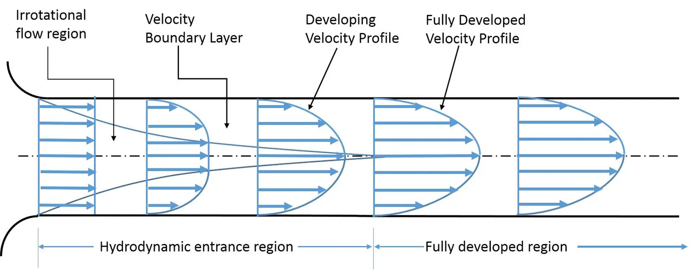
`v_(avg) = (Re*mu)/(D*rho)` = 0.0935 m/s
`v_(max) = 2*v_(avg)`= 0.1869 m/s
This is derived from Reynold's number formula.
`mu` = dynamic viscosity and `rho`= density.
Hagen Poiseuille's Equation
In nonideal fluid dynamics, the Hagen–Poiseuille equation, also known as the Hagen–Poiseuille law, is a physical law that gives the pressure drop in an incompressible and Newtonian fluid in laminar flow flowing through a long cylindrical pipe of constant cross section.
Pressure difference `DeltaP = (32 *mu*L*V_(avg))/D^2`
In order to reduce computational time, we reduce the pipe geometry required for simulation. This is possible since the flow is axi-symmetric. We assume wedge angle `theta` = 2 deg.
SIMULATION STEPS
Step 1: As the case being solved for is laminar and axi-symmetric flow, the icoFoam solver to used. So, the cavity folder is copied from turorials file to the run file.
Step 2: A MATLAB script is written to generate blockMeshDict file by taking assumed and corrseponding calculated values.
Code
clear all
close all
clc

% Assumed parameters
re = 2100; %Reynold's number
d = 0.02; %Diameter of pipe
r = d/2; %Radius
theta = 2; %angle of assumed pipe wedge
rho = 1000; %Density at 20 deg C
mu = 8.9e-4; %Dynamic viscosity at 25 deg C
nu = mu/rho;
le = 0.06*re*d; %Entry Length
l = le+0.5; %Total length of pipe
vavg = (re*mu)/(rho*d);
vmax = vavg*2;
delp = (32*mu*l*vavg)/(d*d);
kine_p = delp/rho;

%BlockMeshDict File generator using a series of fprintf statements

f1 = fopen('blockMeshDict','w');

    fprintf(f1,'%s rn','/*--------------------------------*- C++ -*----------------------------------*'); %header
    fprintf(f1,'%s rn','  =========                 |');
    fprintf(f1,'%s rn','  \      /  F ield         | OpenFOAM: The Open Source CFD Toolbox');
    fprintf(f1,'%s rn','   \    /   O peration     | Website:  https://openfoam.org');
    fprintf(f1,'%s rn','    \  /    A nd           | Version:  8');
    fprintf(f1,'%s rn','     \/     M anipulation  |');
    fprintf(f1,'%s rn','*---------------------------------------------------------------------------*/'); %description
    fprintf(f1,'%s rn','FoamFile');
    fprintf(f1,'%s rn','{');
    fprintf(f1,'%s rn','    version     2.0;');
    fprintf(f1,'%s rn','    format      ascii;');
    fprintf(f1,'%s rn','    class       dictionary;');
    fprintf(f1,'%s rn','    object      blockMeshDict;');
    fprintf(f1,'%s rn','}');
    fprintf(f1,'%s rnrn','// * * * * * * * * * * * * * * * * * * * * * * * * * * * * * * * * * * * * * //');
    fprintf(f1,'%s rnrn','convertToMeters 1;'); %conversion factor for units
    fprintf(f1,'%s rn','vertices'); %plotting vertices
    fprintf(f1,'%s rn','(');
    fprintf(f1,'    (%f %f %f) rn',0,0,0);                                %0
    fprintf(f1,'    (%f %f %f) rn',0,r*cosd(theta/2),r*sind(theta/2));    %1
    fprintf(f1,'    (%f %f %f) rn',0,r*cosd(theta/2),-r*sind(theta/2));   %2
    fprintf(f1,'    (%f %f %f) rn',l,0,0);                                %3
    fprintf(f1,'    (%f %f %f) rn',l,r*cosd(theta/2),r*sind(theta/2));    %4
    fprintf(f1,'    (%f %f %f) rn',l,r*cosd(theta/2),-r*sind(theta/2));   %5
    fprintf(f1,'%s rnrn',');');
    fprintf(f1,'%s rn','blocks'); %mesh blocks
    fprintf(f1,'%s rn','(');
    fprintf(f1,'%s rn','    hex (0 2 1 0 3 5 4 3) (30 1 350) simpleGrading (0.1 1 10)');
    fprintf(f1,'%s rnrn',');');
    fprintf(f1,'%s rn','edges'); %creating arcs
    fprintf(f1,'%s rn','(');
    fprintf(f1,'    arc 2 1 (%f %f %f) rn',0,r,0);
    fprintf(f1,'    arc 5 4 (%f %f %f) rn',l,r,0);
    fprintf(f1,'%s rnrn',');');
    fprintf(f1,'%s rn','boundary'); %boundaries definition
    fprintf(f1,'%s rn','(');
    fprintf(f1,'%s rn','    inlet'); %flow inlet
    fprintf(f1,'%s rn','    {');
    fprintf(f1,'%s rn','        type patch;');
    fprintf(f1,'%s rn','        faces');
    fprintf(f1,'%s rn','        (');
    fprintf(f1,'%s rn','            (0 1 2 0)');
    fprintf(f1,'%s rn','        );');
    fprintf(f1,'%s rn','    }');
    fprintf(f1,'%s rn','    outlet');%flow outlet
    fprintf(f1,'%s rn','    {');
    fprintf(f1,'%s rn','        type patch;');
    fprintf(f1,'%s rn','        faces');
    fprintf(f1,'%s rn','        (');
    fprintf(f1,'%s rn','            (3 5 4 3)');
    fprintf(f1,'%s rn','        );');
    fprintf(f1,'%s rn','    }');
    fprintf(f1,'%s rn','    front'); %side wall - front
    fprintf(f1,'%s rn','    {');
    fprintf(f1,'%s rn','        type wedge;');
    fprintf(f1,'%s rn','        faces');
    fprintf(f1,'%s rn','        (');
    fprintf(f1,'%s rn','            (3 4 1 0)');
    fprintf(f1,'%s rn','        );');
    fprintf(f1,'%s rn','    }');
    fprintf(f1,'%s rn','    back');%side wall - back
    fprintf(f1,'%s rn','    {');
    fprintf(f1,'%s rn','        type wedge;');
    fprintf(f1,'%s rn','        faces');
    fprintf(f1,'%s rn','        (');
    fprintf(f1,'%s rn','            (3 0 2 5)');
    fprintf(f1,'%s rn','        );');
    fprintf(f1,'%s rn','    }');
    fprintf(f1,'%s rn','    pipecurvature'); % curved wall - pipewall
    fprintf(f1,'%s rn','    {');
    fprintf(f1,'%s rn','        type wall;');
    fprintf(f1,'%s rn','        faces');
    fprintf(f1,'%s rn','        (');
    fprintf(f1,'%s rn','            (5 2 1 4)');
    fprintf(f1,'%s rn','        );');
    fprintf(f1,'%s rn','    }');
    fprintf(f1,'%s rn','    axis'); % axis - empty line
    fprintf(f1,'%s rn','    {');
    fprintf(f1,'%s rn','        type empty;');
    fprintf(f1,'%s rn','        faces');
    fprintf(f1,'%s rn','        (');
    fprintf(f1,'%s rn','            (0 3 3 0)');
    fprintf(f1,'%s rn','        );');
    fprintf(f1,'%s rn','    }');
    fprintf(f1,'%s rnrn',');');
    fprintf(f1,'%s rn','mergePatchPairs'); %merging patch pairs
    fprintf(f1,'%s rn','(');
    fprintf(f1,'%s rnrn',');');
    fprintf(f1,'%s rn','// ************************************************************************* //');


fclose(f1);
Step 3: The generated blockMeshDict file is placed in place of the default blockMeshDict file in the cavity tutorial.
Step 4: Next, relevant boundary fields are set in the pressure and velocity files.
Step 5: In the physical properties file, kinematic viscosity is added. `nu` = `mu`/`rho` = `8.9*10^-7``m^2`/s
Step 6: Now, in the controlDict file, the simulation run time and time steps are added.
Step 7: The simulation setup is completed and it is run by calling the solver name. Then, using paraFoam, postprocessing is done.
BlockMeshDict File
/*--------------------------------*- C++ -*----------------------------------*
  =========                 |
  \      /  F ield         | OpenFOAM: The Open Source CFD Toolbox
   \    /   O peration     | Website:  https://openfoam.org
    \  /    A nd           | Version:  8
     \/     M anipulation  |
*---------------------------------------------------------------------------*/
FoamFile
{
    version     2.0;
    format      ascii;
    class       dictionary;
    object      blockMeshDict;
}
// * * * * * * * * * * * * * * * * * * * * * * * * * * * * * * * * * * * * * //

convertToMeters 1;

vertices
(
    (0.000000 0.000000 0.000000)
    (0.000000 0.009998 0.000175)
    (0.000000 0.009998 -0.000175)
    (3.020000 0.000000 0.000000)
    (3.020000 0.009998 0.000175)
    (3.020000 0.009998 -0.000175)
);

blocks
(
    hex (0 2 1 0 3 5 4 3) (30 1 350) simpleGrading (0.1 1 10)
);

edges
(
    arc 2 1 (0.000000 0.010000 0.000000)
    arc 5 4 (3.020000 0.010000 0.000000)
);

boundary
(
    inlet
    {
        type patch;
        faces
        (
            (0 1 2 0)
        );
    }
    outlet
    {
        type patch;
        faces
        (
            (3 5 4 3)
        );
    }
    front
    {
        type wedge;
        faces
        (
            (3 4 1 0)
        );
    }
    back
    {
        type wedge;
        faces
        (
            (3 0 2 5)
        );
    }
    pipecurvature
    {
        type wall;
        faces
        (
            (5 2 1 4)
        );
    }
    axis
    {
        type empty;
        faces
        (
            (0 3 3 0)
        );
    }
);

mergePatchPairs
(
);

// ************************************************************************* //
controlDict File
/*--------------------------------*- C++ -*----------------------------------*
  =========                 |
  \      /  F ield         | OpenFOAM: The Open Source CFD Toolbox
   \    /   O peration     | Website:  https://openfoam.org
    \  /    A nd           | Version:  8
     \/     M anipulation  |
*---------------------------------------------------------------------------*/
FoamFile
{
    version     2.0;
    format      ascii;
    class       dictionary;
    location    "system";
    object      controlDict;
}
// * * * * * * * * * * * * * * * * * * * * * * * * * * * * * * * * * * * * * //

application     icoFoam;

startFrom       startTime;

startTime       0;

stopAt          endTime;

endTime         10;

deltaT          0.01;

writeControl    timeStep;

writeInterval   20;

purgeWrite      0;

writeFormat     ascii;

writePrecision  6;

writeCompression off;

timeFormat      general;

timePrecision   6;

runTimeModifiable true;


// ************************************************************************* //
Pressure File
/*--------------------------------*- C++ -*----------------------------------*
  =========                 |
  \      /  F ield         | OpenFOAM: The Open Source CFD Toolbox
   \    /   O peration     | Website:  https://openfoam.org
    \  /    A nd           | Version:  8
     \/     M anipulation  |
*---------------------------------------------------------------------------*/
FoamFile
{
    version     2.0;
    format      ascii;
    class       volScalarField;
    object      p;
}
// * * * * * * * * * * * * * * * * * * * * * * * * * * * * * * * * * * * * * //

dimensions      [0 2 -2 0 0 0 0];

internalField   uniform 0;

boundaryField
{
    inlet
    {
        type            zeroGradient;
        //type            fixedValue;
        //value           uniform 20.1;
    }

    outlet
    {
        type            fixedValue;
        value           uniform 0.020094;
    }

    pipecurvature
    {
        type            zeroGradient;
    }

    front
    {
        type            wedge;
    }

    back
    {
        type            wedge;
    }

    axis
    {
        type            empty;
    }
}

// ************************************************************************* //
Velocity File
/*--------------------------------*- C++ -*----------------------------------*
  =========                 |
  \      /  F ield         | OpenFOAM: The Open Source CFD Toolbox
   \    /   O peration     | Website:  https://openfoam.org
    \  /    A nd           | Version:  8
     \/     M anipulation  |
*---------------------------------------------------------------------------*/
FoamFile
{
    version     2.0;
    format      ascii;
    class       volVectorField;
    object      U;
}
// * * * * * * * * * * * * * * * * * * * * * * * * * * * * * * * * * * * * * //

dimensions      [0 1 -1 0 0 0 0];

internalField   uniform (0 0 0);

boundaryField
{
    inlet
    {
        type            fixedValue;
        value           uniform (0.0935 0 0);
    }

    outlet
    {
        type            zeroGradient;
    }

    front
    {
        type            wedge;
    }

    back
    {
        type            wedge;
    }

    axis
    {
        type            empty;
    }

    pipecurvature
    {
        type            noSlip;
    }
}

// ************************************************************************* //
transportProperties File
/*--------------------------------*- C++ -*----------------------------------*
  =========                 |
  \      /  F ield         | OpenFOAM: The Open Source CFD Toolbox
   \    /   O peration     | Website:  https://openfoam.org
    \  /    A nd           | Version:  8
     \/     M anipulation  |
*---------------------------------------------------------------------------*/
FoamFile
{
    version     2.0;
    format      ascii;
    class       dictionary;
    location    "constant";
    object      transportProperties;
}
// * * * * * * * * * * * * * * * * * * * * * * * * * * * * * * * * * * * * * //

nu              [0 2 -1 0 0 0 0] 0.00000089;


// ************************************************************************* //
RESULTS
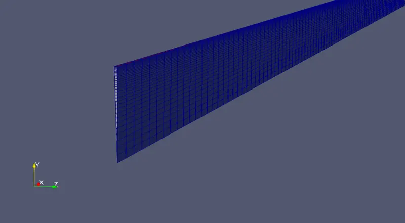
1. Meshed Geometry
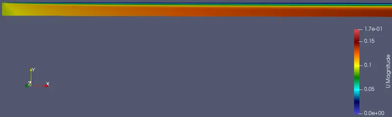
2. Velocity gradient at inlet
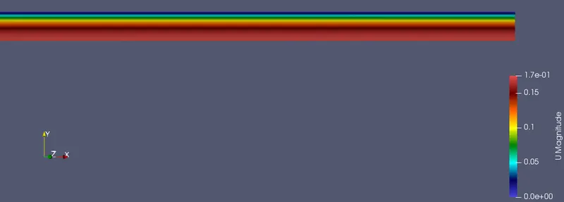
3. Velocity gradient at outlet
4. Pressure gradient
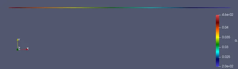
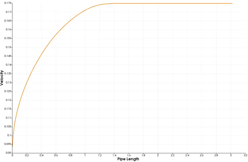
5. Velocity plot from 0 to L.
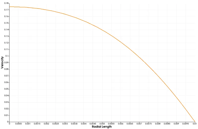
6. Velocity plot at a distance of 2.52
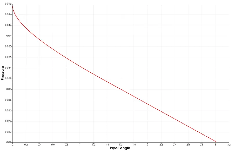
7. Pressure drop across the length of the pipe
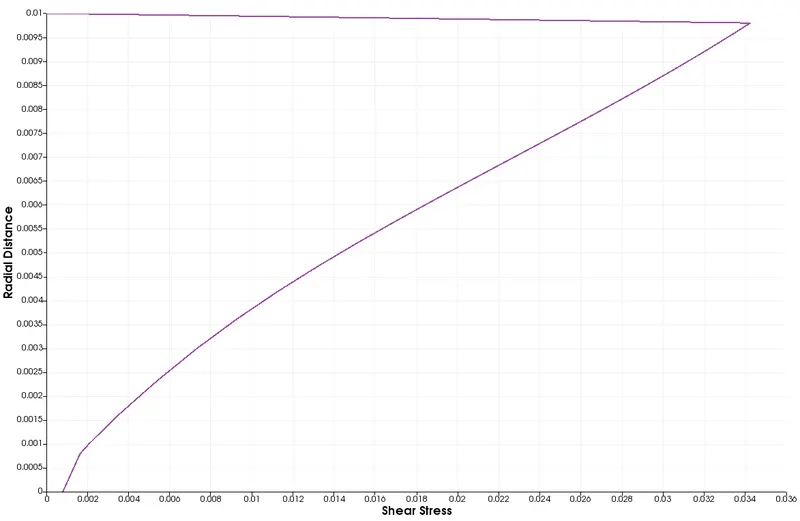
8. Shear stress across radial distance at pipe length = 2.52m
CONCLUSIONS
1. The theoretical hydrodynamic length is 2.52m. But from the velocity plot, it is seen that the flow is developed at a distance of approx. 1.53 m from the inlet. This means that our flow is developing earlier than calculated.
2. The theoretical max velocity was calculated to be 0.1869 m/s. The numerical max velocity was approx. 0.1748 m/s. Therefore, velocity percentage error is approx. 6.47 %.
3. The theoretical pressure drop was calculated to be 20.0940 Pa where as the numerical pressure drop was approx. 25.42 Pa. Therefore, pressure drop has a percentage error of 26.5 %.
4. The shear stress plot shows that the maximum stress occurs close to the wall which is according to the shear stress profile.