CFD meshing on Turbocharger
AIM
To clean up the given model and perform first, surface meshing got the given mesh lengths and then to perform volumetric meshing for revelent volumes.
PROCEDURE
- The first step is to import the geometry and run a geometry check.
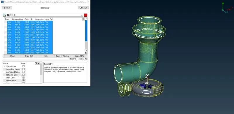
- Using the geometry check, all the surfaces that need to be fixed (single cons, triple cons, overlapping features) are identified.
- ‘Delete’, ‘Intersect’, ‘Cut’, and ‘New’ tools under faces are used to fix the geometry.
- ‘Release’ tool is also used for triple cons as required.
- For the fan/propeller area, to perform delete, new cons need to be projected.
- In the bottom part of the model, to fill a surface, conventional direct is not possible. So, new hot points are added which then allows us to use previously used tools for filling the surface.
- It is important to ensure that the inside of shaft, impeller, and the blades form one single volume, i.e., that there are no multiple overlapping faces between them.
- There are also triple cons, which upon closer inspection, are the ones mainly added up due to open surfaces being closed for meshing.
- All property ids are added and applied as required.
- The geometry is ready for surface meshing.
- Mesh lengths are applied as follows:
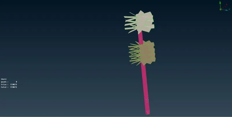
Blade stage 1 = 1 mm
Blade stage 2 = 1 mm
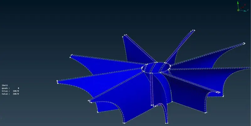
Impeller = 2 mm
Shaft rotor = 1 mm
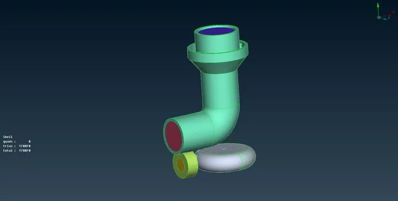
Turbo casing (With inlet and outlet) = 5 mm
Compressor casing (With inlet and outlet) = 5 mm
Inlet casing cover = 5 mm
- For the above-mentioned mesh lengths, relevant maximum and minimum mesh lengths are also applied.
- After all the meshing is done, it can be observed that some mesh has disappeared. This happens due to different mesh lengths of 2 or more connected parts.
- These surfaces can be re-meshed. After 1 surface is re-meshed, we can mesh the other connecting surfaces without changing macros and/or perimeter length parameter. This ensures that the mesh between 2 or more connected parts are connected properly.
- Triangular mesh is used for surface meshing. The total no. of elements is 919064.
- Now, we move on to volumetric meshing. First, we switch to vol. meshing deck.
- Now we define all the volumes in the whole database.
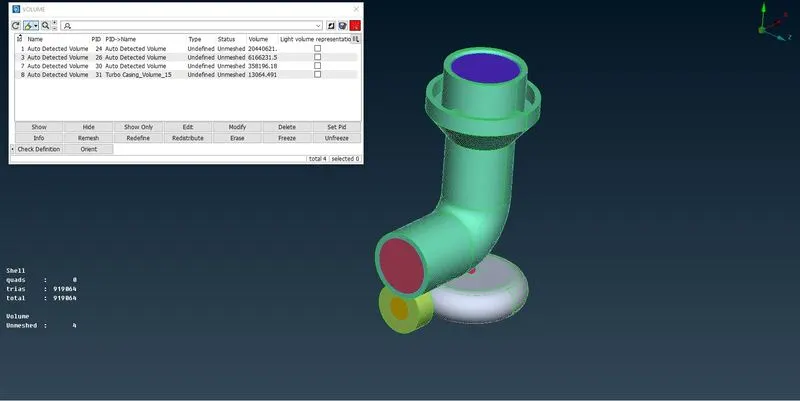
- Then, we delete volumes which are essentially thickness volumes and there will be now fluid flow in them.
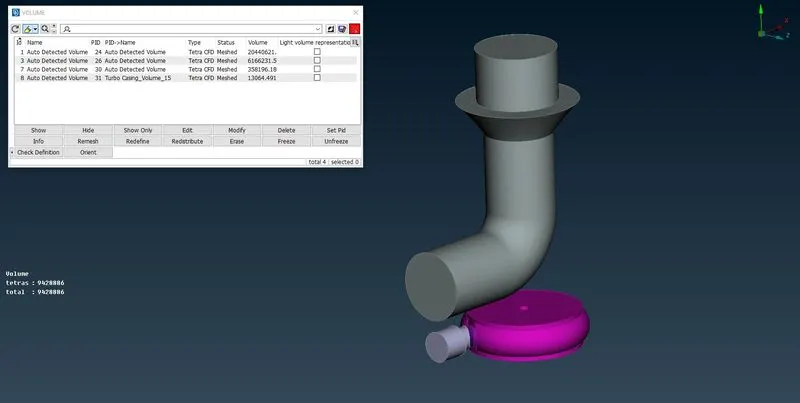
- The volumes are unmeshed and need to be meshed. Under remesh, tetra CFD mesh option is used to mesh the volumes.
- The meshed volumes have a total of 9428886 tetra elements.
RESULTS AND PROCESS IMAGES
1. Imported model into ANSA
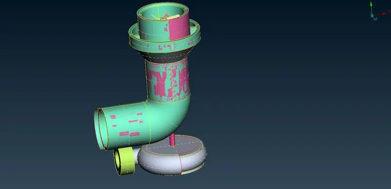
2. Geometry check
2.1 Before Geometry Clean Up
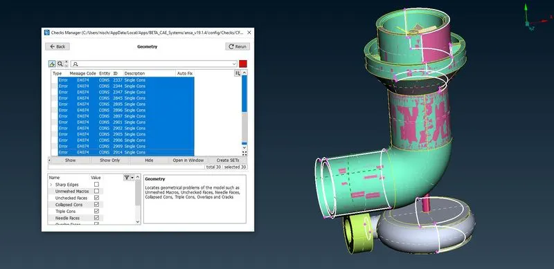
2.2 After Geometry Clean Up
3. Assigened PIDs
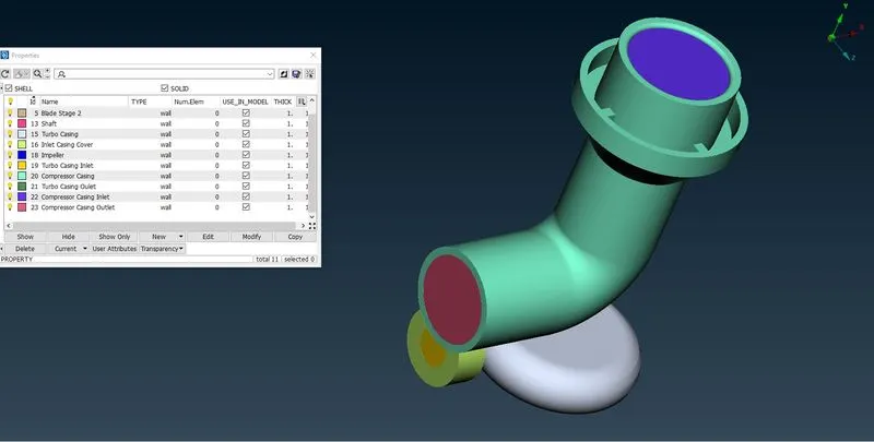
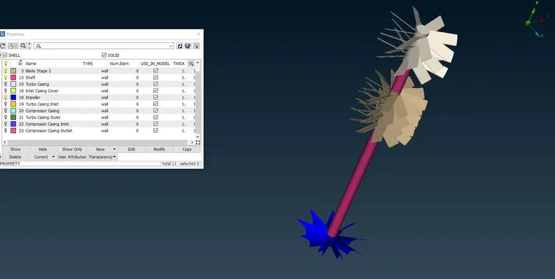
4. Surface mesh
4.1 5mm meshed parts
4.2 2mm meshed part
4.3 1mm meshed parts
4.4 All meshed parts
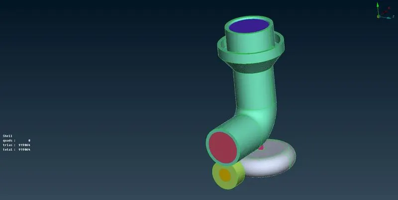
5. Volumetric mesh
5.1 Volumes definition
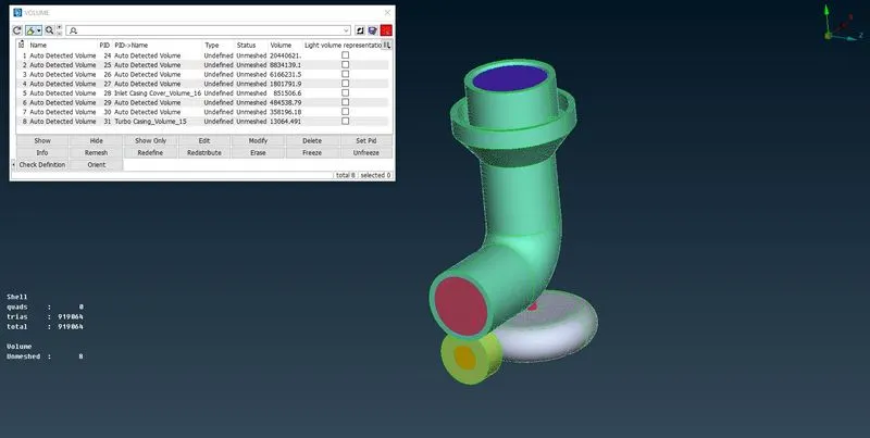
5.2 Keeping only relevant volumes where flow occurs
5.3 Meshed volumes
CONCLUSION
The required surface mesh and volumetric mesh are obtained. The surface mesh has a total of 919064 elements. The meshed volumes have a total of 9428886 tetra elements.
File Link : https://drive.google.com/file/d/1H_24dZpRVgMNUGOfjSoErkc5bwTvWIG9/view?usp=sharing