Validation studies of Symmetry BC vs Wedge BC in OpenFOAM vs Analytical H.P equation
AIM
To simulate an axi-symmetric flow by applying the wedge and symmetry boundary conditions at various angles in openfoam.
THEORY
Here, a pipe of diameter of 20mm is considered. The flow is assumed as laminar and flows through a constant cross-section pipe at an inlet Reynold's number of 2100. Fluid is considered as water. Density of water = 1000 `(kg)/m^3`, and dynamic viscosity `mu` = 8.9x`10^-4`Pa.s . Since we assume Re = 2100, it means that the flow will be laminar.
Entry length is given by the formula `L = 0.06*Re*D`
where, D = diamater of the pipe.
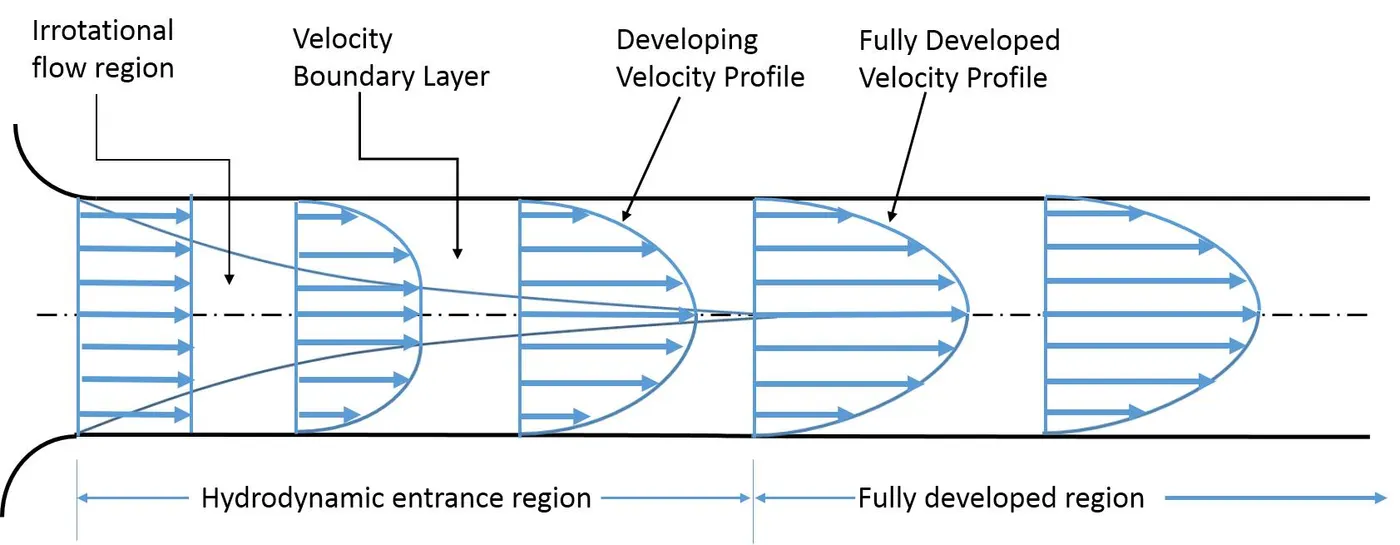
`v_(avg) = (Re*mu)/(D*rho)` = 0.0935 m/s
`v_(max) = 2*v_(avg)`= 0.1869 m/s
This is derived from Reynold's number formula.
`mu` = dynamic viscosity and `rho`= density.
Hagen Poiseuille's Equation
In nonideal fluid dynamics, the Hagen–Poiseuille equation, also known as the Hagen–Poiseuille law, is a physical law that gives the pressure drop in an incompressible and Newtonian fluid in laminar flow flowing through a long cylindrical pipe of constant cross section.
Pressure difference `DeltaP = (32 *mu*L*V_(avg))/D^2`
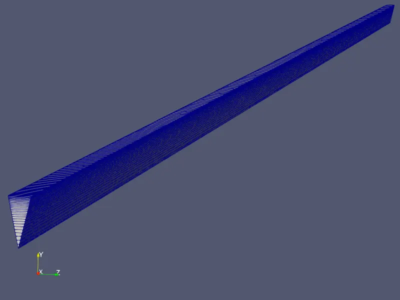
In order to reduce computational time, we reduce the pipe geometry required for simulation. This is possible since the flow is axi-symmetric. The pipe angle for wedge and symmetry condtions are taken at `10^@`, `25^@`, and `45^@`.
SIMULATION STEPS
Step 1: As the case being solved for is laminar and axi-symmetric flow, the icoFoam solver to used. So, the cavity folder is copied from turorials file to the run file. There are a total of six cases to be solved. They are:
| Case No. | Angle | Condtion |
| 1 | `10^@` | Wedge |
| 2 | `10^@` | Symmetry |
| 3 | `25^@` | Wedge |
| 4 | `25^@` | Symmetry |
| 5 | `45^@` | Wedge |
| 6 | `45^@` | Symmetry |
Step 2: A MATLAB script is written to generate blockMeshDict file. The angle and pipe side wall type are changed as per the case being solved.
MATLAB CODE (at `theta = 10^@` and wedge condition)
clear all
close all
clc

% Assumed parameters
re = 2100; %Reynold's number
d = 0.02; %Diameter of pipe
r = d/2; %Radius
theta = 10; %angle of assumed pipe cross section
rho = 1000; %Density at 20 deg C
mu = 8.9e-4; %Dynamic viscosity at 25 deg C
nu = mu/rho;
le = 0.06*re*d; %Entry Length
l = le+0.5; %Total length of pipe
vavg = (re*mu)/(rho*d);
vmax = vavg*2;
delp = (32*mu*l*vavg)/(d*d);
kine_p = delp/rho;

%BlockMeshDict File generator using a series of fprintf statements

f1 = fopen('blockMeshDict','w');

    fprintf(f1,'%s rn','/*--------------------------------*- C++ -*----------------------------------*'); %header
    fprintf(f1,'%s rn','  =========                 |');
    fprintf(f1,'%s rn','  \      /  F ield         | OpenFOAM: The Open Source CFD Toolbox');
    fprintf(f1,'%s rn','   \    /   O peration     | Website:  https://openfoam.org');
    fprintf(f1,'%s rn','    \  /    A nd           | Version:  8');
    fprintf(f1,'%s rn','     \/     M anipulation  |');
    fprintf(f1,'%s rn','*---------------------------------------------------------------------------*/'); %description
    fprintf(f1,'%s rn','FoamFile');
    fprintf(f1,'%s rn','{');
    fprintf(f1,'%s rn','    version     2.0;');
    fprintf(f1,'%s rn','    format      ascii;');
    fprintf(f1,'%s rn','    class       dictionary;');
    fprintf(f1,'%s rn','    object      blockMeshDict;');
    fprintf(f1,'%s rn','}');
    fprintf(f1,'%s rnrn','// * * * * * * * * * * * * * * * * * * * * * * * * * * * * * * * * * * * * * //');
    fprintf(f1,'%s rnrn','convertToMeters 1;'); %conversion factor for units
    fprintf(f1,'%s rn','vertices'); %plotting vertices
    fprintf(f1,'%s rn','(');
    fprintf(f1,'    (%f %f %f) rn',0,0,0);                                %0
    fprintf(f1,'    (%f %f %f) rn',0,r*cosd(theta/2),r*sind(theta/2));    %1
    fprintf(f1,'    (%f %f %f) rn',0,r*cosd(theta/2),-r*sind(theta/2));   %2
    fprintf(f1,'    (%f %f %f) rn',l,0,0);                                %3
    fprintf(f1,'    (%f %f %f) rn',l,r*cosd(theta/2),r*sind(theta/2));    %4
    fprintf(f1,'    (%f %f %f) rn',l,r*cosd(theta/2),-r*sind(theta/2));   %5
    fprintf(f1,'%s rnrn',');');
    fprintf(f1,'%s rn','blocks'); %mesh blocks
    fprintf(f1,'%s rn','(');
    fprintf(f1,'%s rn','    hex (0 2 1 0 3 5 4 3) (30 1 350) simpleGrading (0.1 1 10)');
    fprintf(f1,'%s rnrn',');');
    fprintf(f1,'%s rn','edges'); %creating arcs
    fprintf(f1,'%s rn','(');
    fprintf(f1,'    arc 2 1 (%f %f %f) rn',0,r,0);
    fprintf(f1,'    arc 5 4 (%f %f %f) rn',l,r,0);
    fprintf(f1,'%s rnrn',');');
    fprintf(f1,'%s rn','boundary'); %boundaries definition
    fprintf(f1,'%s rn','(');
    fprintf(f1,'%s rn','    inlet'); %flow inlet
    fprintf(f1,'%s rn','    {');
    fprintf(f1,'%s rn','        type patch;');
    fprintf(f1,'%s rn','        faces');
    fprintf(f1,'%s rn','        (');
    fprintf(f1,'%s rn','            (0 1 2 0)');
    fprintf(f1,'%s rn','        );');
    fprintf(f1,'%s rn','    }');
    fprintf(f1,'%s rn','    outlet');%flow outlet
    fprintf(f1,'%s rn','    {');
    fprintf(f1,'%s rn','        type patch;');
    fprintf(f1,'%s rn','        faces');
    fprintf(f1,'%s rn','        (');
    fprintf(f1,'%s rn','            (3 5 4 3)');
    fprintf(f1,'%s rn','        );');
    fprintf(f1,'%s rn','    }');
    fprintf(f1,'%s rn','    front'); %side wall - front
    fprintf(f1,'%s rn','    {');
    fprintf(f1,'%s rn','        type wedge;');
    fprintf(f1,'%s rn','        faces');
    fprintf(f1,'%s rn','        (');
    fprintf(f1,'%s rn','            (3 4 1 0)');
    fprintf(f1,'%s rn','        );');
    fprintf(f1,'%s rn','    }');
    fprintf(f1,'%s rn','    back');%side wall - back
    fprintf(f1,'%s rn','    {');
    fprintf(f1,'%s rn','        type wedge;');
    fprintf(f1,'%s rn','        faces');
    fprintf(f1,'%s rn','        (');
    fprintf(f1,'%s rn','            (3 0 2 5)');
    fprintf(f1,'%s rn','        );');
    fprintf(f1,'%s rn','    }');
    fprintf(f1,'%s rn','    pipecurvature'); % curved wall - pipewall
    fprintf(f1,'%s rn','    {');
    fprintf(f1,'%s rn','        type wall;');
    fprintf(f1,'%s rn','        faces');
    fprintf(f1,'%s rn','        (');
    fprintf(f1,'%s rn','            (5 2 1 4)');
    fprintf(f1,'%s rn','        );');
    fprintf(f1,'%s rn','    }');
    fprintf(f1,'%s rn','    axis'); % axis - empty line
    fprintf(f1,'%s rn','    {');
    fprintf(f1,'%s rn','        type empty;');
    fprintf(f1,'%s rn','        faces');
    fprintf(f1,'%s rn','        (');
    fprintf(f1,'%s rn','            (0 3 3 0)');
    fprintf(f1,'%s rn','        );');
    fprintf(f1,'%s rn','    }');
    fprintf(f1,'%s rnrn',');');
    fprintf(f1,'%s rn','mergePatchPairs'); %merging patch pairs
    fprintf(f1,'%s rn','(');
    fprintf(f1,'%s rnrn',');');
    fprintf(f1,'%s rn','// ************************************************************************* //');


fclose(f1);
Step 3: The generated blockMeshDict file is placed in place of the default blockMeshDict file in the cavity tutorial.
Step 4: Next, relevant boundary fields are set in the pressure and velocity files.
Step 5: In the physical properties file, kinematic viscosity is added. `nu` = `mu`/`rho` = `8.9*10^-7``m^2`/s
Step 6: Now, in the controlDict file, the simulation run time and time steps are added.
Step 7: The simulation setup is completed and it is run by calling the solver name. Then, using paraFoam, postprocessing is done.
Step 8: The above steps are the same for all the cases.
blockMeshDict File (Symmetry) (`theta = 10^@`)
/*--------------------------------*- C++ -*----------------------------------*
  =========                 |
  \      /  F ield         | OpenFOAM: The Open Source CFD Toolbox
   \    /   O peration     | Website:  https://openfoam.org
    \  /    A nd           | Version:  8
     \/     M anipulation  |
*---------------------------------------------------------------------------*/
FoamFile
{
    version     2.0;
    format      ascii;
    class       dictionary;
    object      blockMeshDict;
}
// * * * * * * * * * * * * * * * * * * * * * * * * * * * * * * * * * * * * * //

convertToMeters 1;

vertices
(
    (0.000000 0.000000 0.000000)
    (0.000000 0.009962 0.000872)
    (0.000000 0.009962 -0.000872)
    (3.020000 0.000000 0.000000)
    (3.020000 0.009962 0.000872)
    (3.020000 0.009962 -0.000872)
);

blocks
(
    hex (0 2 1 0 3 5 4 3) (30 1 350) simpleGrading (0.1 1 10)
);

edges
(
    arc 2 1 (0.000000 0.010000 0.000000)
    arc 5 4 (3.020000 0.010000 0.000000)
);

boundary
(
    inlet
    {
        type patch;
        faces
        (
            (0 1 2 0)
        );
    }
    outlet
    {
        type patch;
        faces
        (
            (3 5 4 3)
        );
    }
    front
    {
        type symmetry;
        faces
        (
            (3 4 1 0)
        );
    }
    back
    {
        type symmetry;
        faces
        (
            (3 0 2 5)
        );
    }
    pipecurvature
    {
        type wall;
        faces
        (
            (5 2 1 4)
        );
    }
    axis
    {
        type empty;
        faces
        (
            (0 3 3 0)
        );
    }
);

mergePatchPairs
(
);

// ************************************************************************* //
Pressure File
/*--------------------------------*- C++ -*----------------------------------*
  =========                 |
  \      /  F ield         | OpenFOAM: The Open Source CFD Toolbox
   \    /   O peration     | Website:  https://openfoam.org
    \  /    A nd           | Version:  8
     \/     M anipulation  |
*---------------------------------------------------------------------------*/
FoamFile
{
    version     2.0;
    format      ascii;
    class       volScalarField;
    object      p;
}
// * * * * * * * * * * * * * * * * * * * * * * * * * * * * * * * * * * * * * //

dimensions      [0 2 -2 0 0 0 0];

internalField   uniform 0;

boundaryField
{
    inlet
    {
        type            zeroGradient;
    }

    outlet
    {
        type            fixedValue;
        value           uniform 0.020094;
    }

    front
    {
        type            symmetry;
    }

    back
    {
        type            symmetry;
    }

    pipecurvature
    {
        type            zeroGradient;
    }

    axis
    {
        type            empty;
    }
}

// ************************************************************************* //
Velocity File
/*--------------------------------*- C++ -*----------------------------------*
  =========                 |
  \      /  F ield         | OpenFOAM: The Open Source CFD Toolbox
   \    /   O peration     | Website:  https://openfoam.org
    \  /    A nd           | Version:  8
     \/     M anipulation  |
*---------------------------------------------------------------------------*/
FoamFile
{
    version     2.0;
    format      ascii;
    class       volVectorField;
    object      U;
}
// * * * * * * * * * * * * * * * * * * * * * * * * * * * * * * * * * * * * * //

dimensions      [0 1 -1 0 0 0 0];

internalField   uniform (0 0 0);

boundaryField
{
    inlet
    {
        type            fixedValue;
        value           uniform (0.0935 0 0);
    }

    outlet
    {
        type            zeroGradient;
    }

    front
    {
        type            symmetry;
    }

    back
    {
        type            symmetry;
    }

    pipecurvature
    {
        type            noSlip;
    }

    axis
    {
        type            empty;
    }
}

// ************************************************************************* //
controlDict File
/*--------------------------------*- C++ -*----------------------------------*
  =========                 |
  \      /  F ield         | OpenFOAM: The Open Source CFD Toolbox
   \    /   O peration     | Website:  https://openfoam.org
    \  /    A nd           | Version:  8
     \/     M anipulation  |
*---------------------------------------------------------------------------*/
FoamFile
{
    version     2.0;
    format      ascii;
    class       dictionary;
    location    "system";
    object      controlDict;
}
// * * * * * * * * * * * * * * * * * * * * * * * * * * * * * * * * * * * * * //

application     icoFoam;

startFrom       startTime;

startTime       0;

stopAt          endTime;

endTime         10;

deltaT          0.01;

writeControl    timeStep;

writeInterval   20;

purgeWrite      0;

writeFormat     ascii;

writePrecision  6;

writeCompression off;

timeFormat      general;

timePrecision   6;

runTimeModifiable true;


// ************************************************************************* //
transportProperties File
/*--------------------------------*- C++ -*----------------------------------*
  =========                 |
  \      /  F ield         | OpenFOAM: The Open Source CFD Toolbox
   \    /   O peration     | Website:  https://openfoam.org
    \  /    A nd           | Version:  8
     \/     M anipulation  |
*---------------------------------------------------------------------------*/
FoamFile
{
    version     2.0;
    format      ascii;
    class       dictionary;
    location    "constant";
    object      transportProperties;
}
// * * * * * * * * * * * * * * * * * * * * * * * * * * * * * * * * * * * * * //

nu              [0 2 -1 0 0 0 0] 8.9e-7;


// ************************************************************************* //
SIMULATION RESULTS
1. Meshed Geometry (`theta = 25^@`)
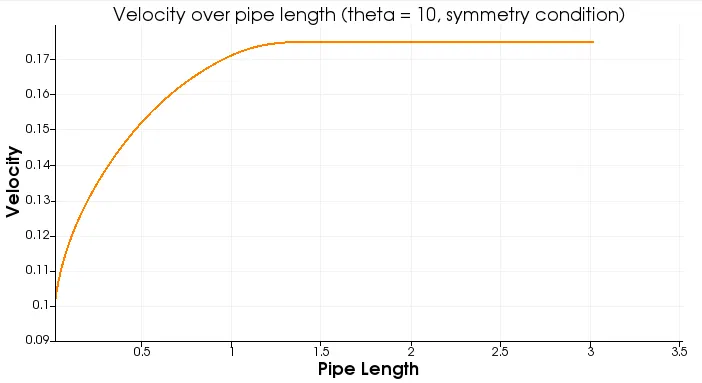
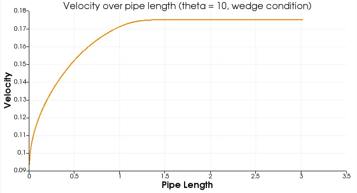
2. Velocity Profiles over pipe length
2.1 `theta = 10^@`
2.2 `theta = 25^@`
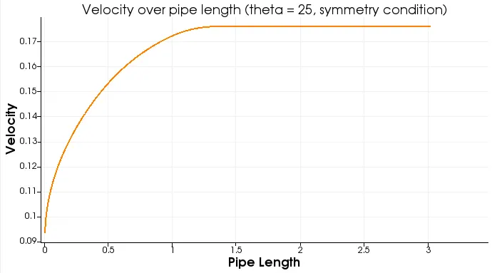
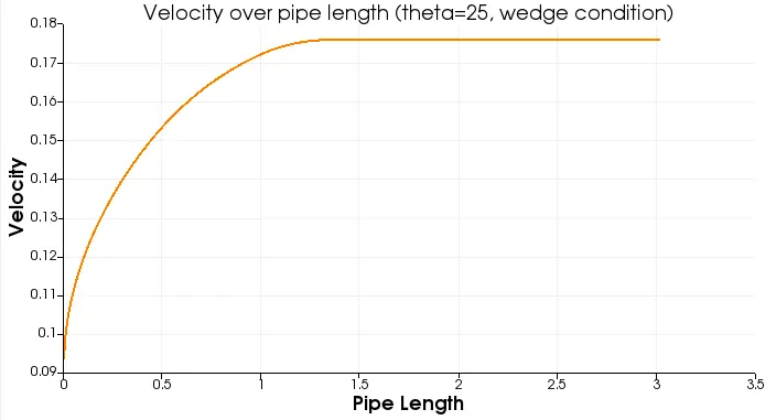
2.3 `theta = 45^@`
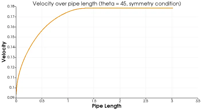
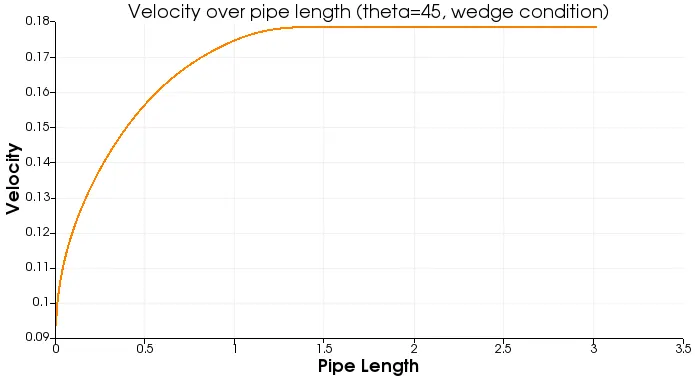
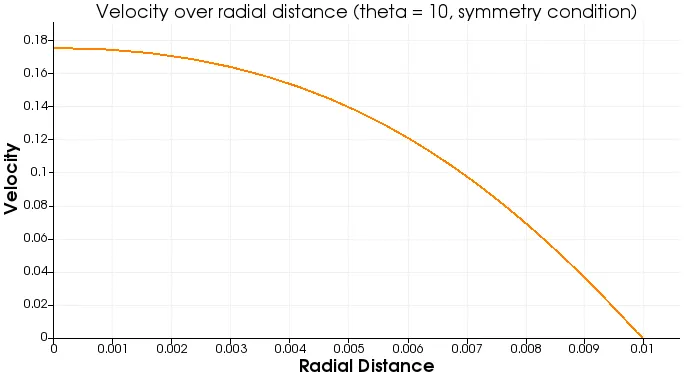
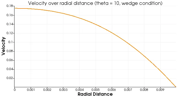
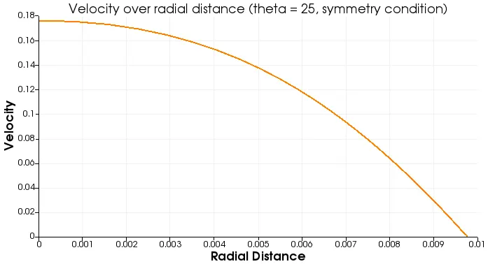
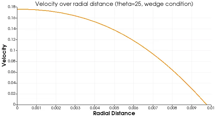
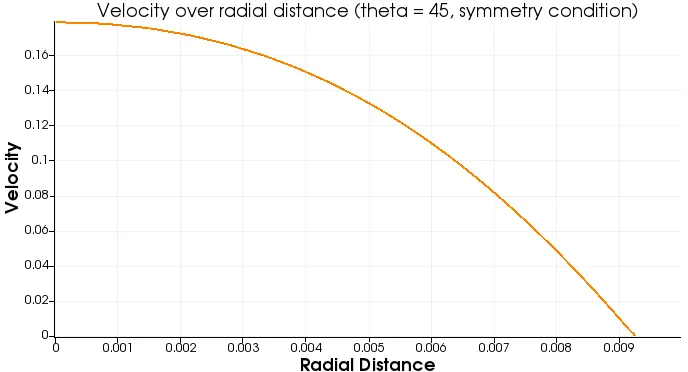
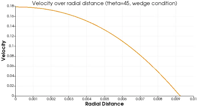
3. Velocity Profiles over radial distance at pipe length x= 2.52 m.
3.1 `theta = 10^@`
3.2 `theta = 25^@`
3.3 `theta = 45^@`
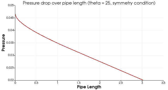
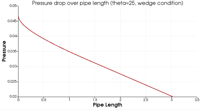
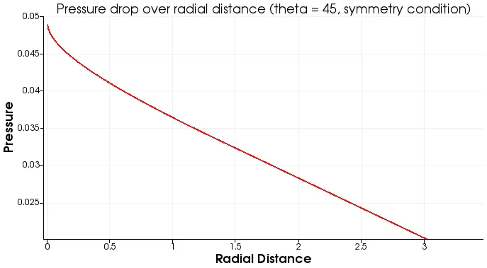
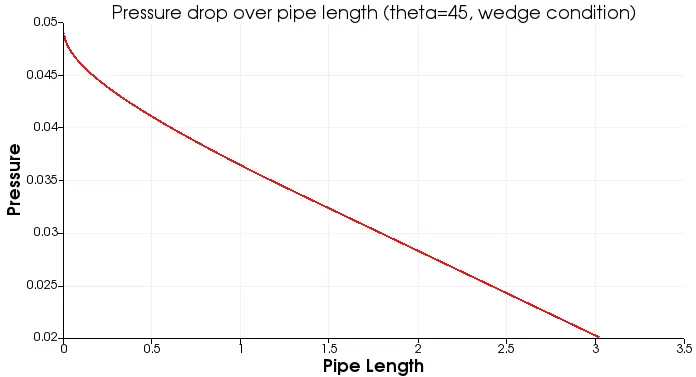
4. Pressure Profile over pipe length
4.1 `theta = 10^@`
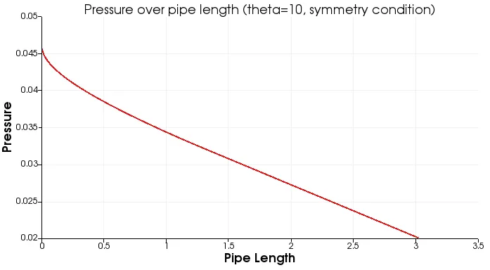
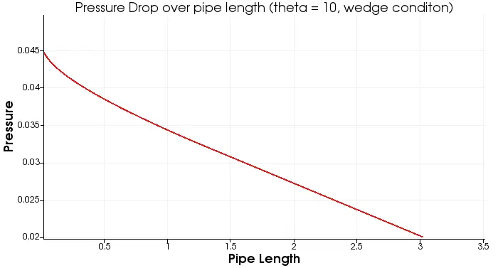
4.2 `theta = 25^@`
4.3 `theta = 45^@`
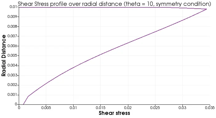
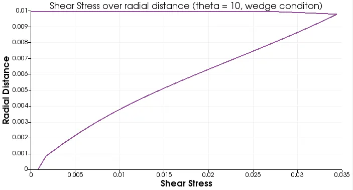
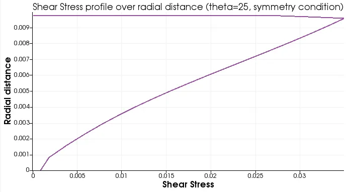
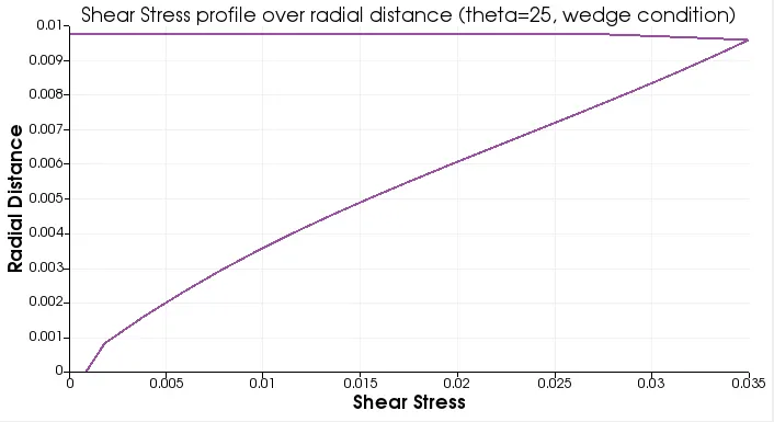
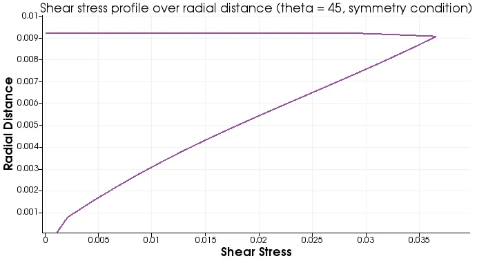
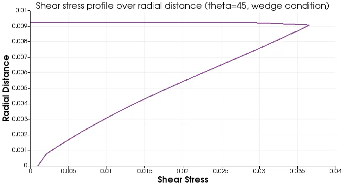
5. Shear Stress profile at x= 2.52 m.
5.1 `theta = 10^@`
5.2 `theta = 25^@`
5.3 `theta = 45^@`
CONCLUSIONS
1. The velocity values in numerical solutions become less accurate as theta increases.
2. The hydrodynamic length is approx. 1.51m to 1.56m in numerical solution. This means that the flow is getting developed earlier than the theoretical hydrodynamic length of 2.52m.
3. The pressure drop values in numerical solutions become less accurate as theta increases.
4. The numerical solutions' shear stress profiles are similar to the theoretical profile.
5. Wedge and symmetry conditions produce almost similar results in all cases with the wedge condition being more accurate of the two by a small margin.