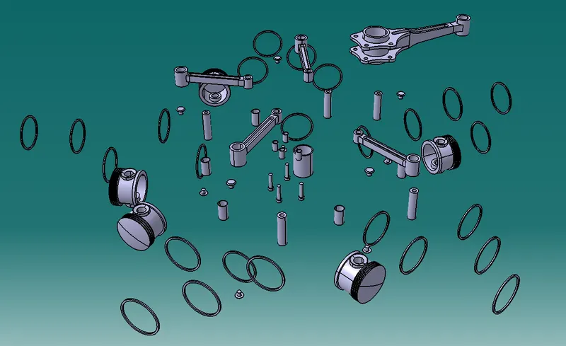
Radial Engine Assembly
PROCEDURE REPORT - Radial Engine assembly
- Top down approach is followed here.
- An assembly design window is opened and a new part is added.
- The sketch of a part is created and then the part itself is created using pad, pocket, etc.
- The same procedure is followed for all 10 parts.
- All 10 parts are individually saved. This can be done using save management also.
- Here, many parts are used multiple times which is done so by reinserting the saved parts again.
- Using contact, coincidence, angular and offset constraints, all the parts are assembled as per the drawing.
- Using ‘Scene’, and exploded view is created and captured.
- A drawing of the front, top, isometric and isometric exploded view is created with the BOM.
Images of Individual Parts :
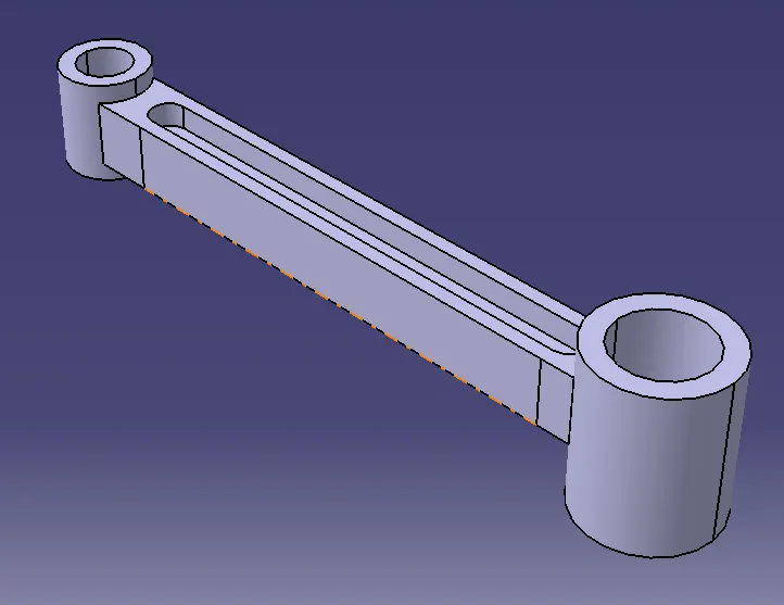
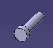
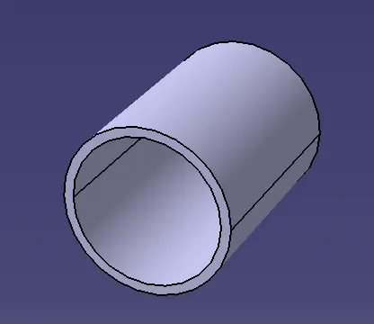
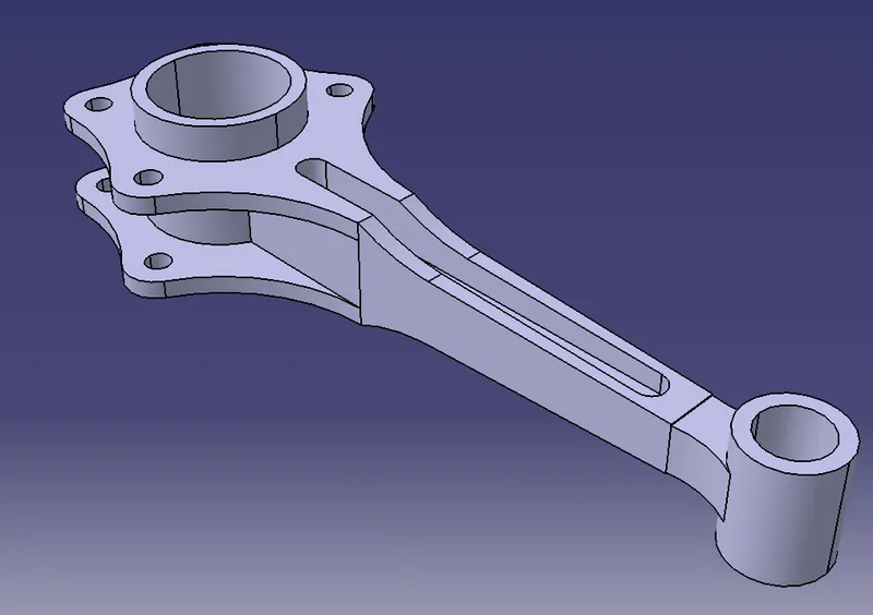
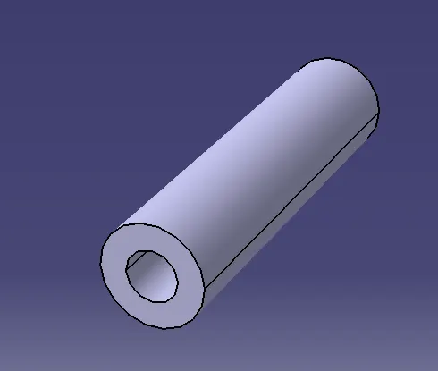
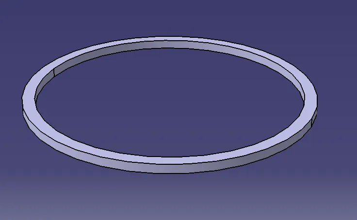
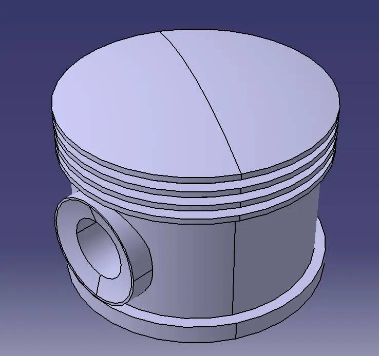
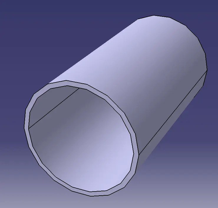
Image of full assembly :
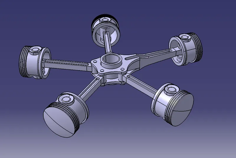
Image of explode view of assembly :