Simulation of a backward facing step in OpenFOAM
AIM
To simulate a incompressible-laminar-viscous flow through a backward facking step in openfoam with mesh grading factor of 1 and 0.2.
SIMULATION SETUP
1. First we copy the tutorial similat to our case to run file. The cavity tutorial under incompressible>icoFoam>cavity is the case which is similar to what we are solving for.
2. After copying, we need to got to the blockMesh file and create out domain by giving its vertices, type of mesh, inlet, outlet, walls, etc. The domain is created as shown below.
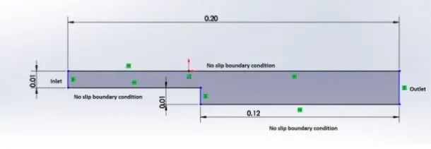
5 blocks are used to create the domain as shown below
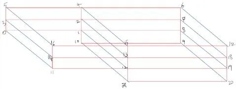
Block Mesh File
/*--------------------------------*- C++ -*----------------------------------*
  =========                 |
  \      /  F ield         | OpenFOAM: The Open Source CFD Toolbox
   \    /   O peration     | Website:  https://openfoam.org
    \  /    A nd           | Version:  10
     \/     M anipulation  |
*---------------------------------------------------------------------------*/
FoamFile
{
    format      ascii;
    class       dictionary;
    object      blockMeshDict;
}
// * * * * * * * * * * * * * * * * * * * * * * * * * * * * * * * * * * * * * //

convertToMeters 1; //value is directly input in meters

vertices
(
    (0 0 0) //vertex at 0
    (0.08 0 0)//vertex at 1
    (0.08 0.005 0)//vertex at 2
    (0 0.005 0)//vertex at 3
    (0.08 0.01 0)//vertex at 4
    (0 0.01 0)//vertex at 5
    (0.2 0.01 0)//vertex at 6
    (0.2 0.005 0)//vertex at 7
    (0.2 0 0)//vertex at 8
    (0.2 -0.01 0)//vertex at 9
    (0.08 -0.01 0)//vertex at 10
    (0 0 0.001)//vertex at 11
    (0.08 0 0.001)//vertex at 12
    (0.08 0.005 0.001)//vertex at 13
    (0 0.005 0.001)//vertex at 14
    (0.08 0.01 0.001)//vertex at 15
    (0 0.01 0.001)//vertex at 16
    (0.2 0.01 0.001)//vertex at 17
    (0.2 0.005 0.001)//vertex at 18
    (0.2 0 0.001)//vertex at 19
    (0.2 -0.01 0.001)//vertex at 20
    (0.08 -0.01 0.001)//vertex at 21

);

blocks
(
    hex (0 1 2 3 11 12 13 14) (80 5 1) simpleGrading (1 1 1) //Block 1
    hex (3 2 4 5 14 13 15 16) (80 5 1) simpleGrading (1 1 1) //Block 2
    hex (2 7 6 4 13 18 17 15) (120 5 1) simpleGrading (1 1 1) //Block 3
    hex (1 8 7 2 12 19 18 13) (120 5 1) simpleGrading (1 1 1) //Block 4
    hex (10 9 8 1 21 20 19 12) (120 10 1) simpleGrading (1 1 1) //Block 5
);

boundary
(
    inlet
    {
        type patch;
        faces
        (
            (0 11 14 3)
	    (3 14 16 5)
        );
    }
    outlet
    {
        type patch;
        faces
        (
            (9 8 19 20)
            (7 6 17 18)
            (8 7 18 19)

        );
    }
    frontAndBack
    {
        type empty;
        faces
        (
            (1 0 3 2)
            (2 3 5 4)
            (7 2 4 6)
            (8 1 2 7)
            (9 10 1 8)
            (11 12 13 14)
            (14 13 15 16)
            (13 18 17 15)
            (12 19 18 13)
            (21 20 19 12)
        );
    }
    noslipwall
    {
        type wall;
        faces
        (
            (16 15 4 5)
            (15 17 6 4)
            (21 10 9 20)
            (10 21 12 1)
            (11 0 1 12)
        );
    }
);

mergePatchPairs
(

);


// ************************************************************************* //
3. We also give details about the simulation time, timesteps etc in the controlDict file.
/*--------------------------------*- C++ -*----------------------------------*
  =========                 |
  \      /  F ield         | OpenFOAM: The Open Source CFD Toolbox
   \    /   O peration     | Website:  https://openfoam.org
    \  /    A nd           | Version:  10
     \/     M anipulation  |
*---------------------------------------------------------------------------*/
FoamFile
{
    format      ascii;
    class       dictionary;
    location    "system";
    object      controlDict;
}
// * * * * * * * * * * * * * * * * * * * * * * * * * * * * * * * * * * * * * //

application     icoFoam;

startFrom       startTime;

startTime       0;

stopAt          endTime;

endTime         3;

deltaT          0.001;

writeControl    timeStep;

writeInterval   20;

purgeWrite      0;

writeFormat     ascii;

writePrecision  6;

writeCompression off;

timeFormat      general;

timePrecision   6;

runTimeModifiable true;


// ************************************************************************* //
4. Now, we update the boundary condtions in the velocity and pressure files.
Velocity file: The velocity is set to 0.2 m/s.
/*--------------------------------*- C++ -*----------------------------------*
  =========                 |
  \      /  F ield         | OpenFOAM: The Open Source CFD Toolbox
   \    /   O peration     | Website:  https://openfoam.org
    \  /    A nd           | Version:  10
     \/     M anipulation  |
*---------------------------------------------------------------------------*/
FoamFile
{
    format      ascii;
    class       volVectorField;
    object      U;
}
// * * * * * * * * * * * * * * * * * * * * * * * * * * * * * * * * * * * * * //

dimensions      [0 1 -1 0 0 0 0];

internalField   uniform (0 0 0);

boundaryField
{
    inlet
    {
        type            fixedValue;
        value           uniform (0.2 0 0);
    }

    outlet
    {
        type            zeroGradient;
    }

    frontAndBack
    {
        type            empty;
    }
    noslipwall
    {
        type            noSlip;
    }

}

// ************************************************************************* //
Pressure File
/*--------------------------------*- C++ -*----------------------------------*
  =========                 |
  \      /  F ield         | OpenFOAM: The Open Source CFD Toolbox
   \    /   O peration     | Website:  https://openfoam.org
    \  /    A nd           | Version:  10
     \/     M anipulation  |
*---------------------------------------------------------------------------*/
FoamFile
{
    format      ascii;
    class       volScalarField;
    object      p;
}
// * * * * * * * * * * * * * * * * * * * * * * * * * * * * * * * * * * * * * //

dimensions      [0 2 -2 0 0 0 0];

internalField   uniform 0;

boundaryField
{
    inlet
    {
        type            zeroGradient;

    }

    outlet
    {
        type            fixedValue;
        value           uniform 0;
    }

    frontAndBack
    {
        type            empty;
    }
    noslipwall
    {
        type            zeroGradient;
    }
}

// ************************************************************************* //
5. We input the kinemetic viscosity in the physicalproperties file.
/*--------------------------------*- C++ -*----------------------------------*
  =========                 |
  \      /  F ield         | OpenFOAM: The Open Source CFD Toolbox
   \    /   O peration     | Website:  https://openfoam.org
    \  /    A nd           | Version:  10
     \/     M anipulation  |
*---------------------------------------------------------------------------*/
FoamFile
{
    format      ascii;
    class       dictionary;
    location    "constant";
    object      physicalProperties;
}
// * * * * * * * * * * * * * * * * * * * * * * * * * * * * * * * * * * * * * //

nu              [0 2 -1 0 0 0 0] 1.48e-5; //kinematic viscosity of air at 20C, units m^2/s


// ************************************************************************* //
6. Our simulation setup is complete and we can run it.
SIMULATION PROCEDURE
1. Once the setup is complete, we run the meshing process using the 'blockMesh' command
2. After meshing, we check the mesh for any issues using the 'checkMesh' command.
3. Using 'paraFoam' we, we open and check the meshing visually in the paraview software.

4. We go back to the command line and use 'icoFoam' to run the solver. Once the simulation is complete, we use paraview again to view the results.
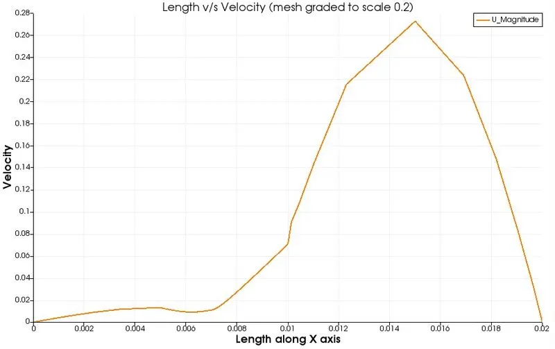
5. In paraview, we use plot over line at (0.085, 0.01, 0.005) to plot velocity w.r.t length.
RESULTS
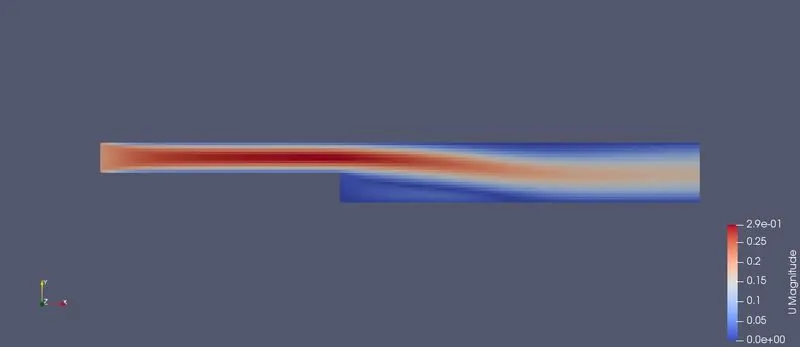
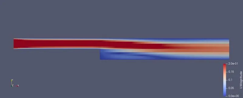
1. Velocity contour at the end
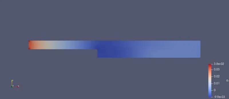
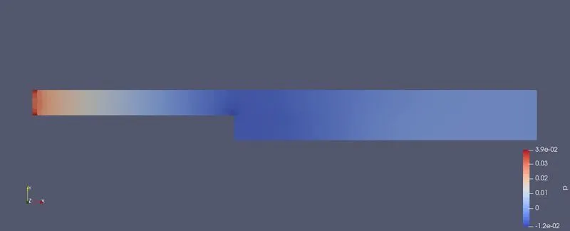
2. Pressure contour at the end
3. Velocity v/s Length along x axis
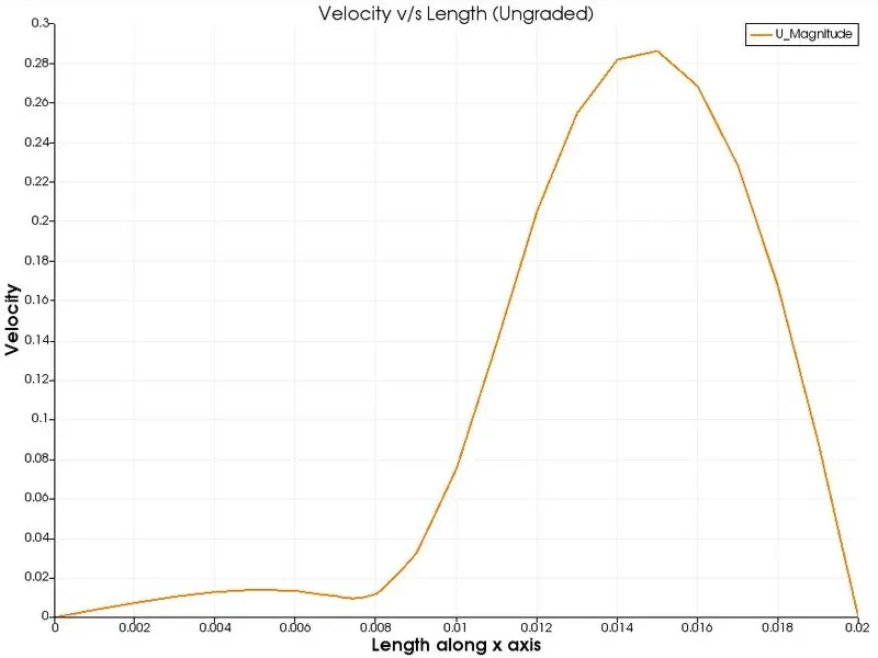
FOR MESH GRADING FACTOR OF 0.2
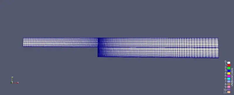
1. The only change we make is, we change the grading factor in the blockMesh file to 0.2 along the required axis. Since the geometry consists of 5 blocks, we need to be careful while inputting the grading factor.
blockMesh file:
/*--------------------------------*- C++ -*----------------------------------*
  =========                 |
  \      /  F ield         | OpenFOAM: The Open Source CFD Toolbox
   \    /   O peration     | Website:  https://openfoam.org
    \  /    A nd           | Version:  10
     \/     M anipulation  |
*---------------------------------------------------------------------------*/
FoamFile
{
    format      ascii;
    class       dictionary;
    object      blockMeshDict;
}
// * * * * * * * * * * * * * * * * * * * * * * * * * * * * * * * * * * * * * //

convertToMeters 1; //value is directly input in meters

vertices
(
    (0 0 0) //vertex at 0
    (0.08 0 0)//vertex at 1
    (0.08 0.005 0)//vertex at 2
    (0 0.005 0)//vertex at 3
    (0.08 0.01 0)//vertex at 4
    (0 0.01 0)//vertex at 5
    (0.2 0.01 0)//vertex at 6
    (0.2 0.005 0)//vertex at 7
    (0.2 0 0)//vertex at 8
    (0.2 -0.01 0)//vertex at 9
    (0.08 -0.01 0)//vertex at 10
    (0 0 0.001)//vertex at 11
    (0.08 0 0.001)//vertex at 12
    (0.08 0.005 0.001)//vertex at 13
    (0 0.005 0.001)//vertex at 14
    (0.08 0.01 0.001)//vertex at 15
    (0 0.01 0.001)//vertex at 16
    (0.2 0.01 0.001)//vertex at 17
    (0.2 0.005 0.001)//vertex at 18
    (0.2 0 0.001)//vertex at 19
    (0.2 -0.01 0.001)//vertex at 20
    (0.08 -0.01 0.001)//vertex at 21

);

blocks
(
    hex (0 1 2 3 11 12 13 14) (80 5 1) simpleGrading (0.2 20 1) //Block 1
    hex (3 2 4 5 14 13 15 16) (80 5 1) simpleGrading (0.2 0.2 1) //Block 2
    hex (2 7 6 4 13 18 17 15) (120 5 1) simpleGrading (20 0.2 1) //Block 3
    hex (1 8 7 2 12 19 18 13) (120 5 1) simpleGrading (20 1 1) //Block 4
    hex (10 9 8 1 21 20 19 12) (120 10 1) simpleGrading (20 20 1) //Block 5
);

boundary
(
    inlet
    {
        type patch;
        faces
        (
            (0 11 14 3)
	    (3 14 16 5)
        );
    }
    outlet
    {
        type patch;
        faces
        (
            (9 8 19 20)
            (7 6 17 18)
            (8 7 18 19)

        );
    }
    frontAndBack
    {
        type empty;
        faces
        (
            (1 0 3 2)
            (2 3 5 4)
            (7 2 4 6)
            (8 1 2 7)
            (9 10 1 8)
            (11 12 13 14)
            (14 13 15 16)
            (13 18 17 15)
            (12 19 18 13)
            (21 20 19 12)
        );
    }
    noslipwall
    {
        type wall;
        faces
        (
            (16 15 4 5)
            (15 17 6 4)
            (21 10 9 20)
            (10 21 12 1)
            (11 0 1 12)
        );
    }
);

mergePatchPairs
(

);


// ************************************************************************* //
Meshed geometry:
Velocity contour at the end
Pressure contour at the end
Velocity v/s Length along x axis
CONCLUSION
Comparing the 2 plots and velocity contours, we find that the grading results in finer data at the point of our interest. The lower the factor, the smoother the mesh will be and the resulting curves will also be smoother.
This means that the grading factor impacts the how refined out countours will be. Although in our case the difference is negligible due to small size of the domain, it will have high impact in real-world based cases.