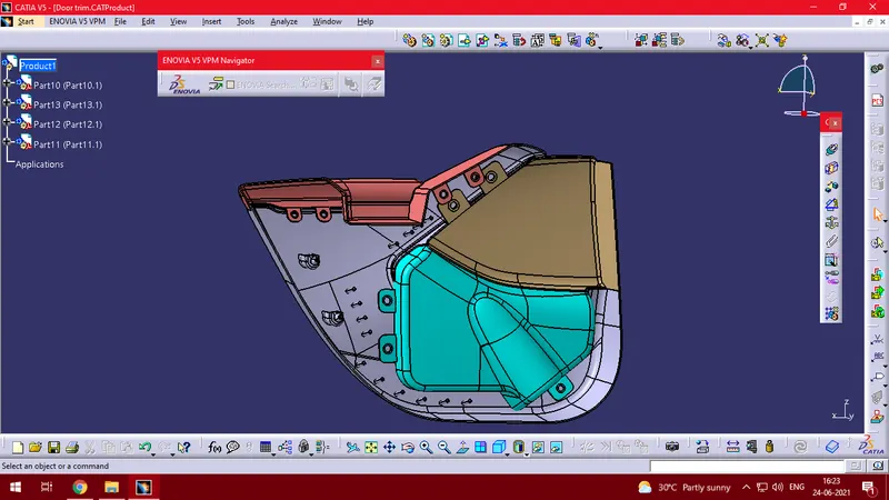
Week 11 - Final project
Door trim
Aim: To create a interior door trim panel for driver door using the given class A surface and master sections.
Introduction: Trims are usually refered to the plastic components which are used mostly in the car interiors. These components are attached to the BIW assembly of the car. These trim parts are designed by an plastic design engineer by considering all the engineering aspects that are required for the functioning of the components. There are various types of plastics which are used to make these trim parts and some of them are listed below:
- Polycarbonate
- Acrylonitrile Butadiene Stryene ABS
- Polyamides (Nylon)
- Polyethylene Terephthalate PET
- Plastic blends
Design considerations for the plastic components.
- Type of plastic to be used
- Type of manufacturing process
- Thickness of the component
- Attachment or joining features such as Ribs, flanges, screw bosses,dog houses etc
- Draft angles, tooling axis and side core axis.
Master Sections
Master scetions are 2D skecthes of the components cross-section which provide so much information for designing a component. Development of master sections require high level skill, knowledge and expertise and hence are developed by design engineers who have at least 8 years of experience or more.
Methodology
| 1 | Performing draft analysis on the given class A surface |
| 2 | Creation of tooling and side core axis for the component |
| 3 | Creation of class B surface |
| 4 | Creation of class C surface |
| 5 | Joining all the three surfaces to form a solid component |
| 6 | Creation of B side or attachment features |
| 7 | Performing the draft analysis on the final component. |
- Arm rest
Draft analysis on class A surface for arm rest
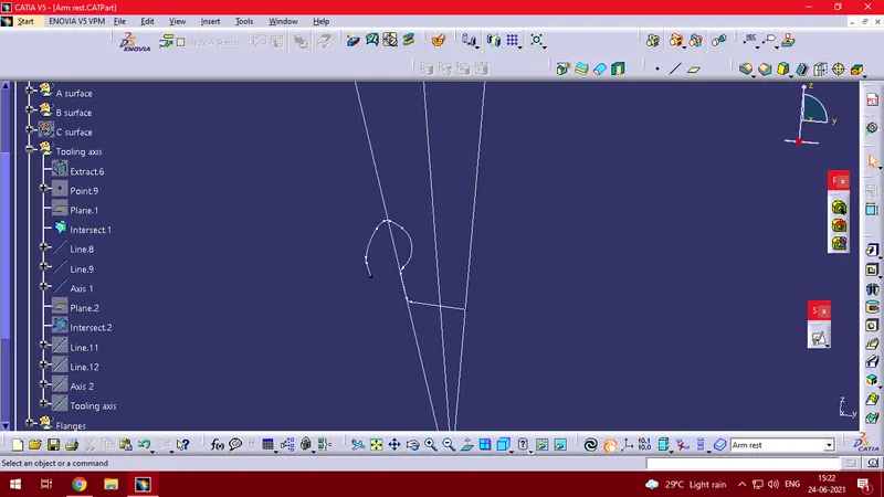
An intersection along the Y axis is taken. One the intersection curve two lines are drawn and a bisector for these two lines is generated which forms the tooling axis along Y axis.
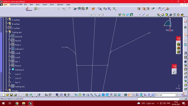
An intersection along X - axis is taken.On the intersection curve two lines are drawn and a bisector for these two lines is generated which forms the tooling axis along X axis.
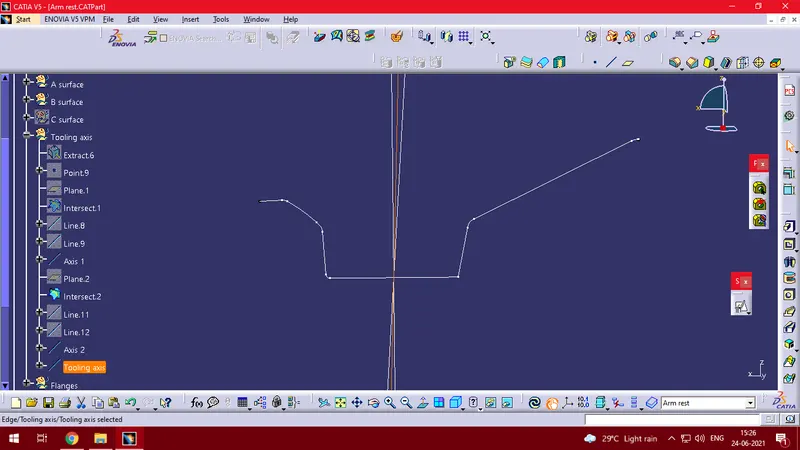
Another bisecting line is created which bisects tooling axis along X and Y. This line forms the tooling axis for the component.
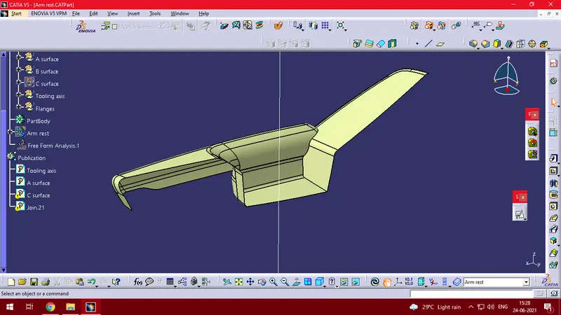
The above image shows the main tooling axis.
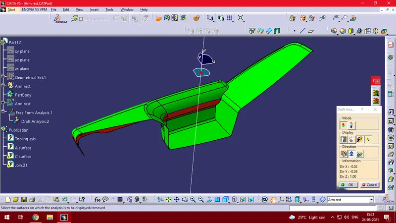
Draft analysis for class A surface.
Class B surface
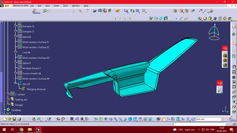
Using class A surface, a class B surface is created.
Class C surface
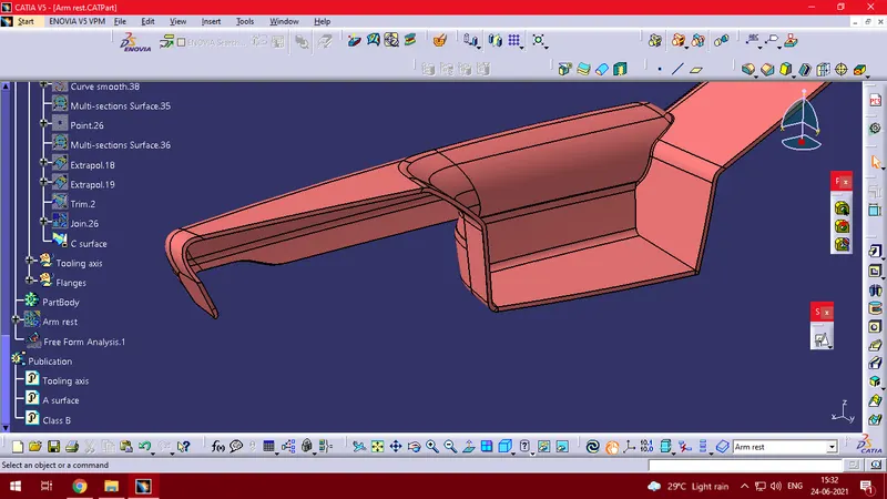
All the 3 surfaces are trimmed together and a solid component is created.
Once the final component is created, attachment features are added.
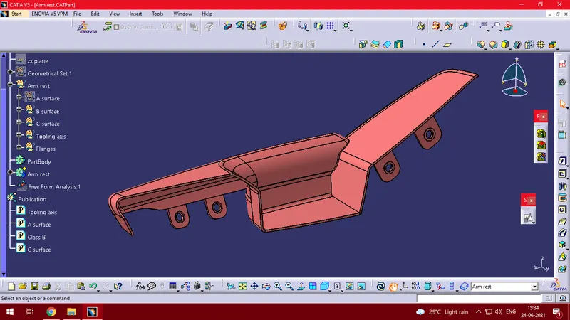
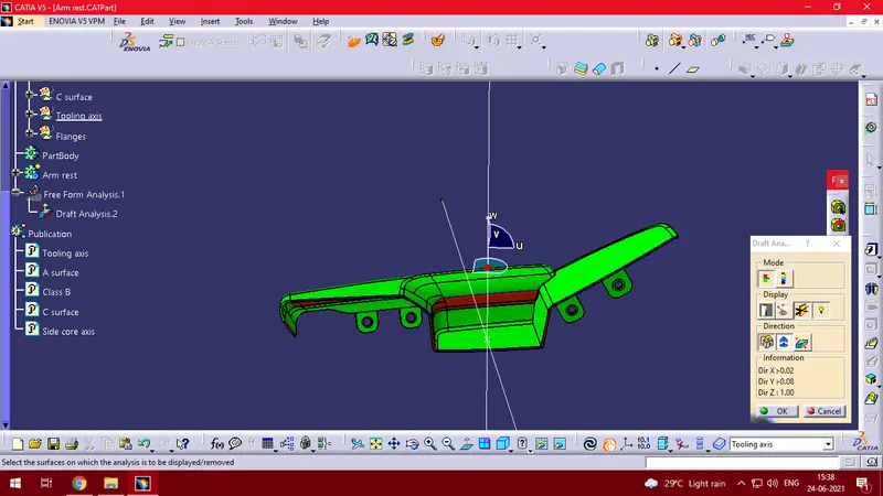
Draft analysis on the main component.
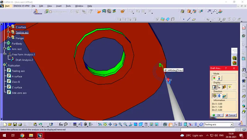
Draft analysis on the flanges
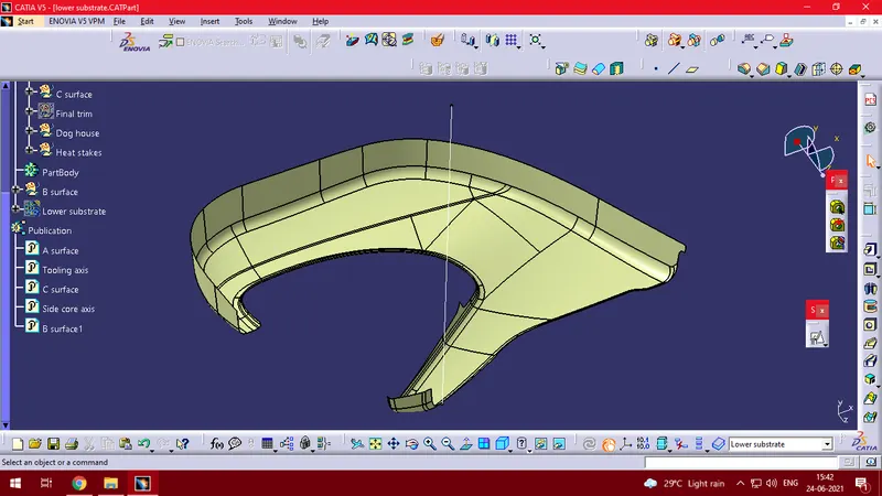
- Lower substrate
Given class A surface
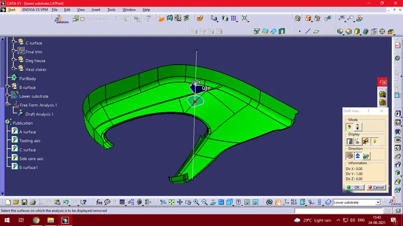
Draft analysis on A surface
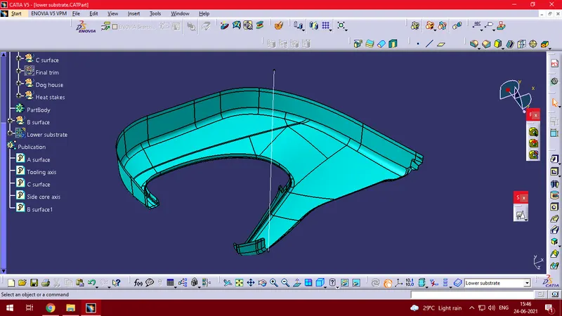
Class B surface
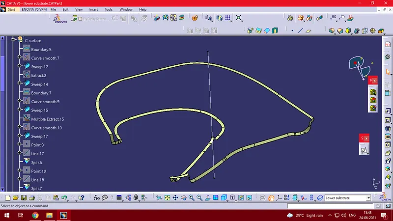
Class C surface
All the 3 surfaces are trimmed together to form a solid component.
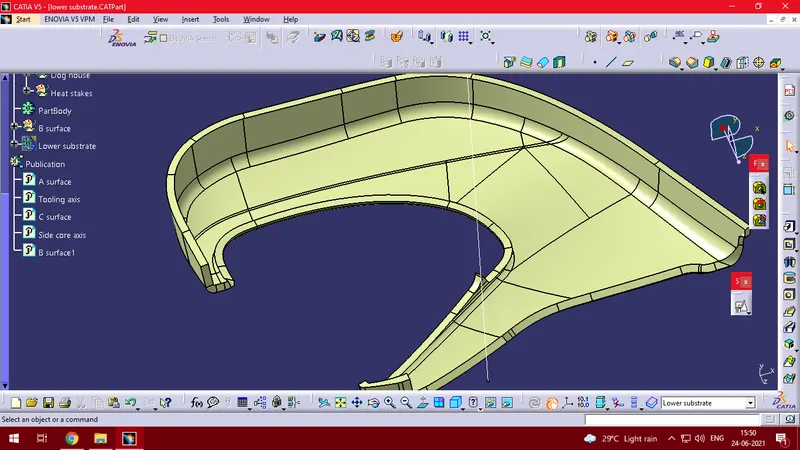
After creating a solid component attachment features are added
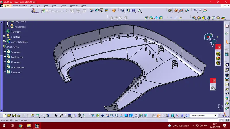
Draft analysis for the final component
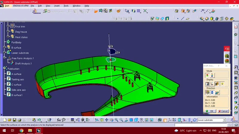
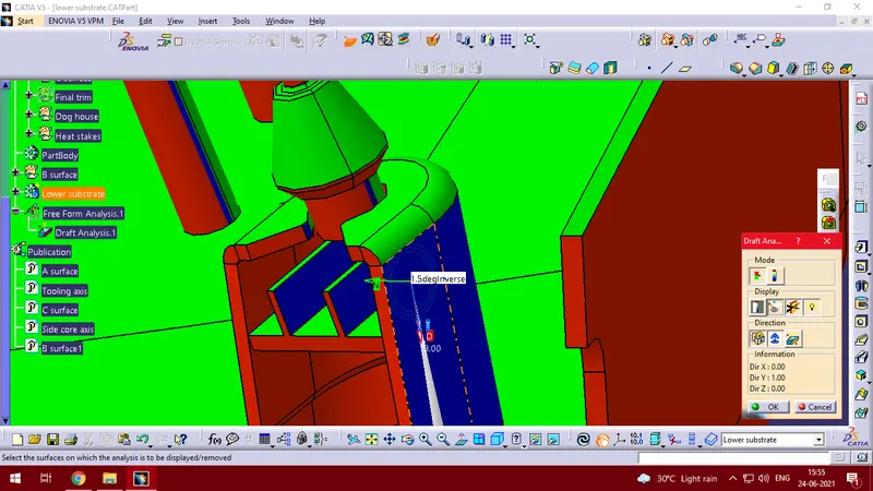
Draft analysis for attachment features
- Upper Map pocket
Given class A surface
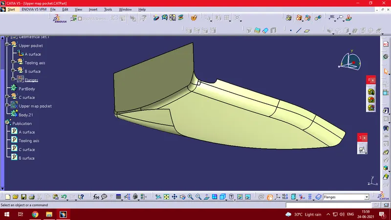
Draft analysis for A surface
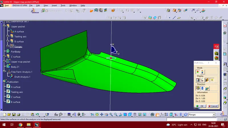
Class B surface
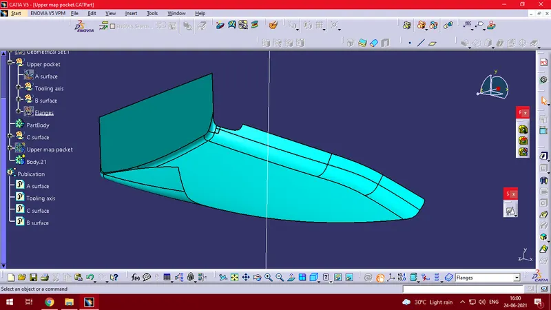
Class C surface
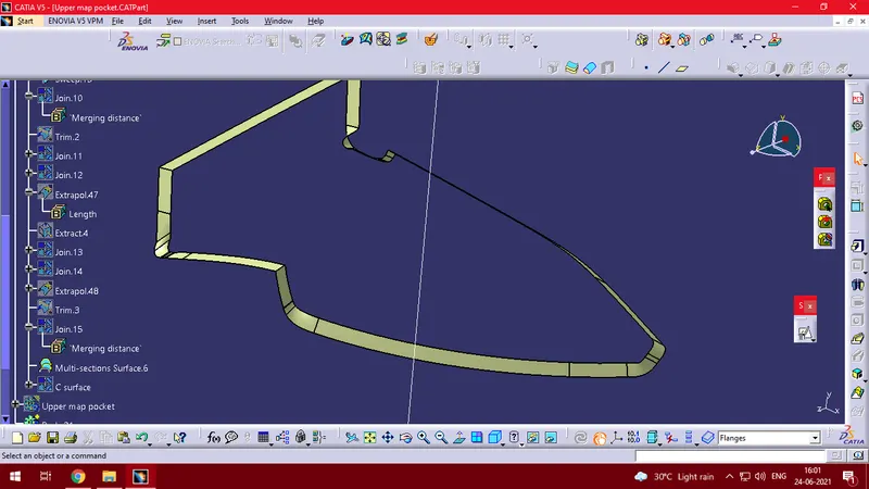
The 3 surfaces are trimmed together to form a solid component
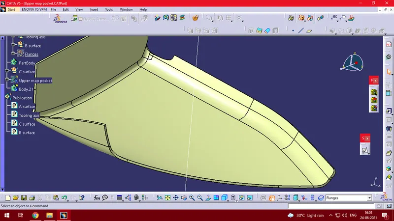
Attachment features are added.
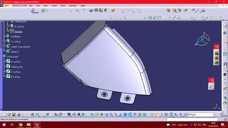
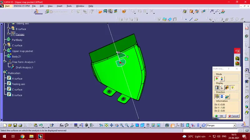
Draft analysis on the final component
- Bottle holder or lower map pocket
Given class A surface
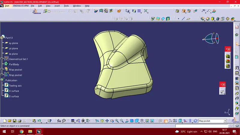
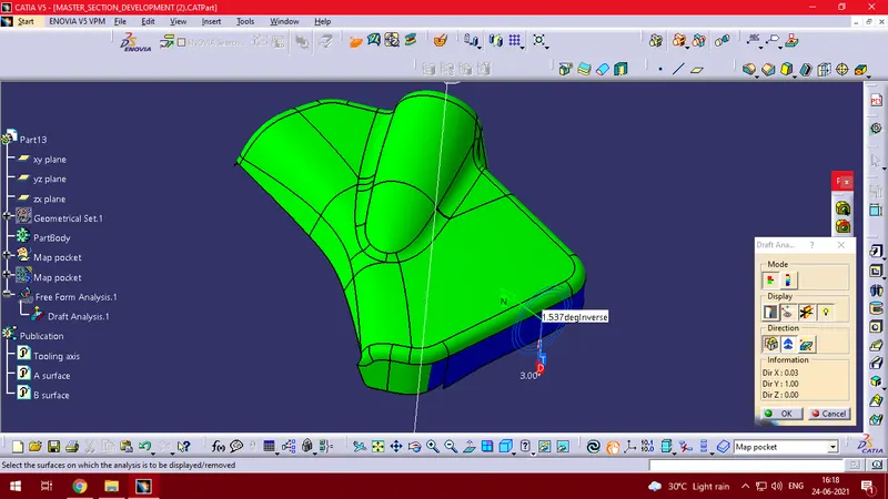
Draft analysis on A surface
Class B surface
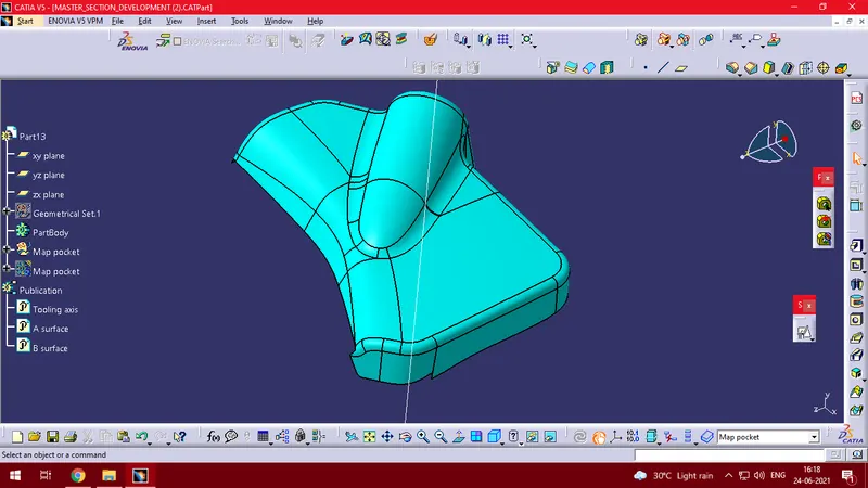
C surface

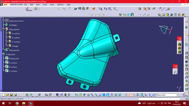
All the 3 surfaces are trimmed together to form a solid component.
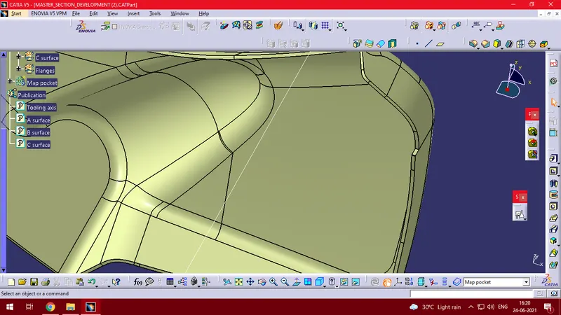
Creation of attachment features
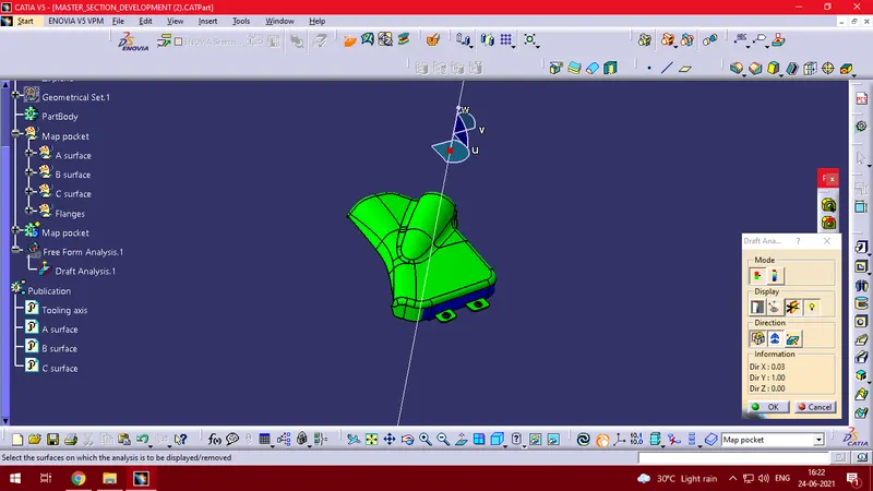
Draft analysis on the final component
Final assembled component