Week 8 - Challenge 5 - Core & Cavity Design
Since thermoplastics shrink as they cool, they grip to cores or male forms in the mold. This makes ejection difficult and may lead to scuff marks on the part. To facilitate ejection, part surfaces parallel to the draw direction of the tool require taper or draft. This draft allows the part to break free by creating a clearance as soon as the mold starts to open. The amount of draft needed depends on several factors:
- Material shrinkage – Some materials shrink more than others. In general, the higher the shrinkage, the larger the draft angle needed to prevent ejection issues.
- Height and shape of wall or feature – A shallow single straight rib having not enough draft causes less problems than a high cylindrical wall.
- Surface texture – A polished surface requires a smaller draft angle than a surface that is textured.
- Aesthetic requirements – Scuff marks might not be as big of a problem on a technical part "hidden" in an assembly while, for the cover part of the assembly, they may be totally unacceptable.
Draft analysis
Given Class A - surface
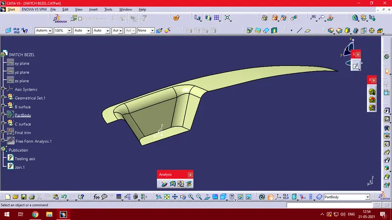
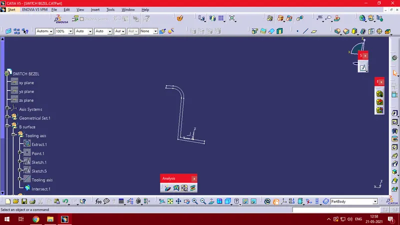
An intersection of the surface is created along its mid-plane
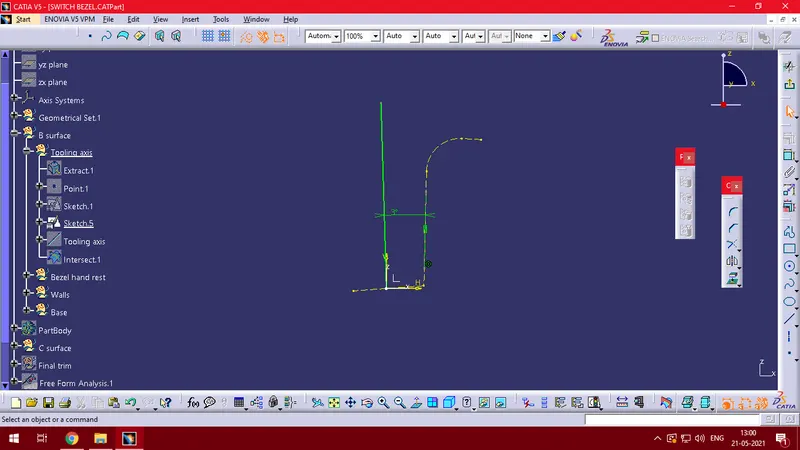
Two lines are drawn on the surfaces which are parallel or almost parallel to the direction of die movement.
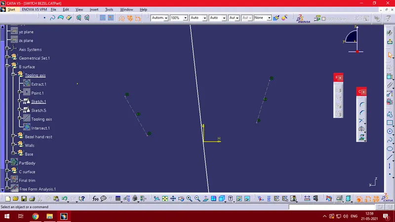
Using these two lines a bisecting line or mean line is created which is the tooling axis of the part.
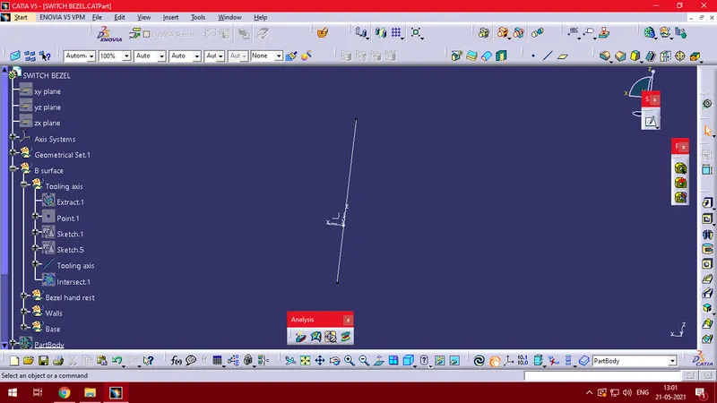
Using this bisecting line as tooling axis draft analysis is carried out. The min. draft angle is 3 degrees.
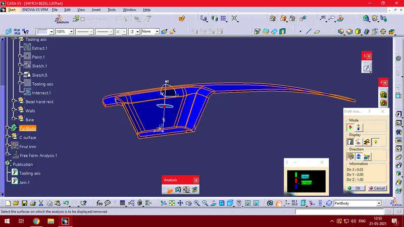
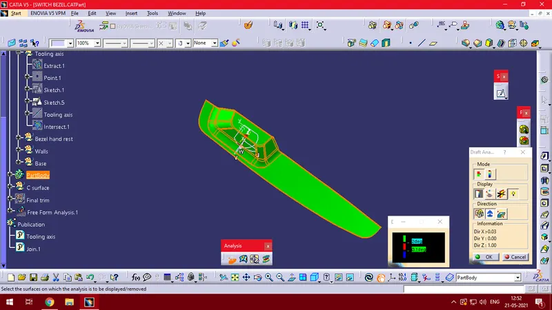
Using the class A surface a class B surface is created.
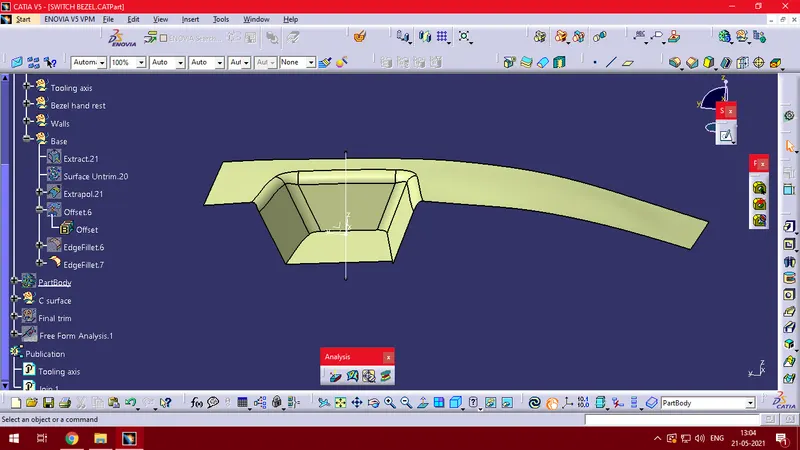
A class C surface is created using class A surface which is used to join both class A&B surfaces.
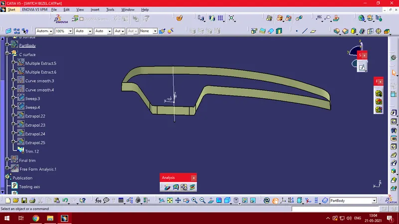
Both class A&C surfaces are joined together and trimmed using class B surface to obtain a thickened component.
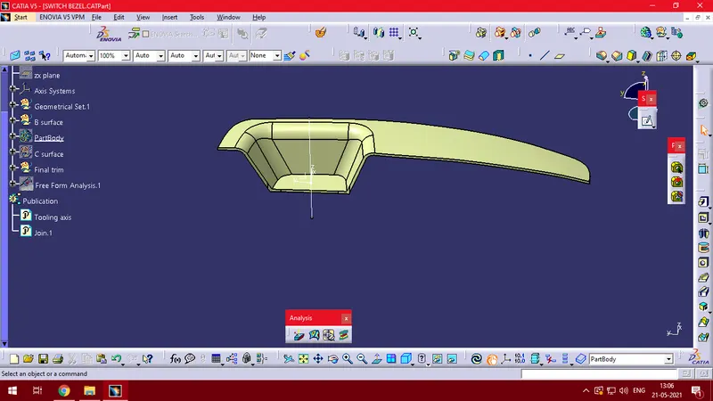
Finally the part is converted into an solid component in the part workbench.
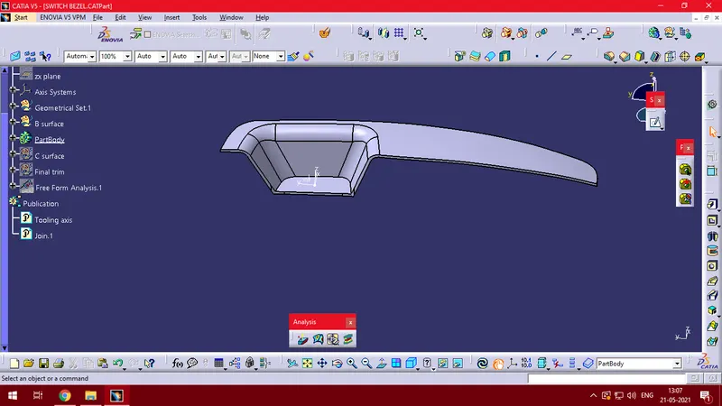
Core and cavity
The core and cavity represent the shape of the desired component. The core is the movable half of the die which has the projection of the shape required whereas the cavity has a depression of the desired shape and forms the lower fixed half of the die.
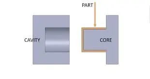
The image shows the core and cavity of the switch bezel component.
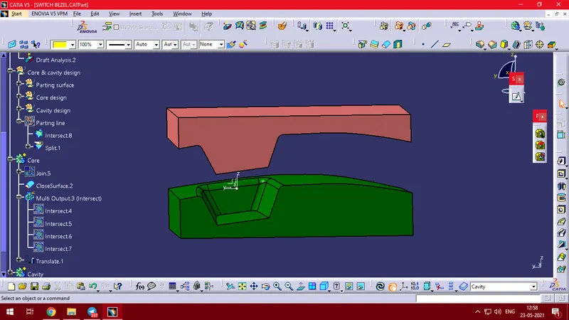
An intersection of the core and cavity.
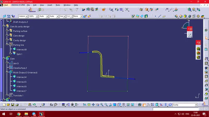
The orange line represents the core
The green rectangle shows the cavity
The blue line is the parting line.
The component is shown in yellow colour.
Parting line and parting surface
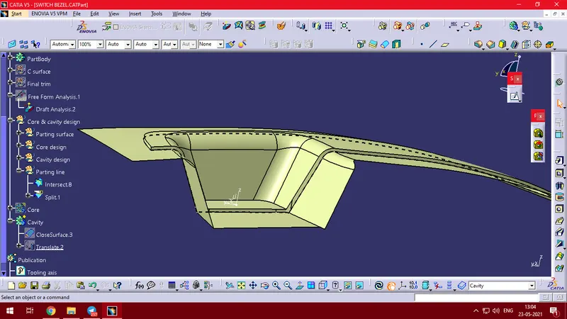
A parting line, in industrial casting of molds, is the border line in which draft angles change direction. That is, it is the dividing line that splits the core and cavity halves of a molded part. It is sometimes a starting point for the mold parting surface.
The black dotted line in the figure below is the parting line.
A parting surface is a surface that separates the mold block into two parts – the core and the cavity.
The surface shown in maroon color is the parting surface that seperates the core and cavity.
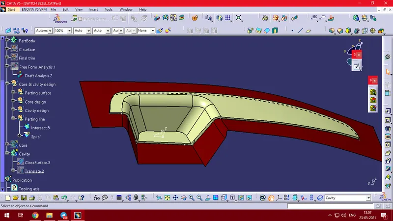
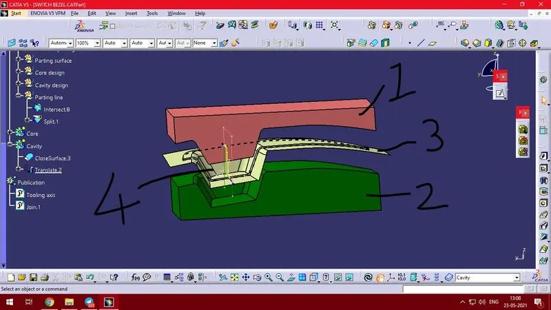
1 - Core
2 - cavity
3 - Parting surface
4 - component