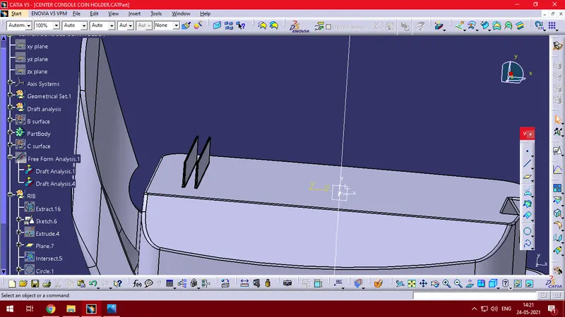
Week 9 - Attachment Feature Creation - Challenge 1
Since thermoplastics shrink as they cool, they grip to cores or male forms in the mold. This makes ejection difficult and may lead to scuff marks on the part. To facilitate ejection, part surfaces parallel to the draw direction of the tool require taper or draft. This draft allows the part to break free by creating a clearance as soon as the mold starts to open. The amount of draft needed depends on several factors:
- Material shrinkage – Some materials shrink more than others. In general, the higher the shrinkage, the larger the draft angle needed to prevent ejection issues.
- Height and shape of wall or feature – A shallow single straight rib having not enough draft causes less problems than a high cylindrical wall.
- Surface texture – A polished surface requires a smaller draft angle than a surface that is textured.
- Aesthetic requirements – Scuff marks might not be as big of a problem on a technical part "hidden" in an assembly while, for the cover part of the assembly, they may be totally unacceptable.
Draft analysis
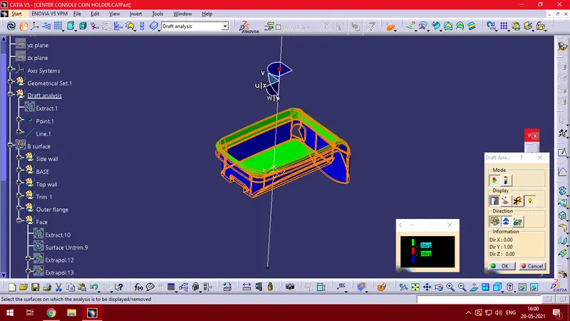
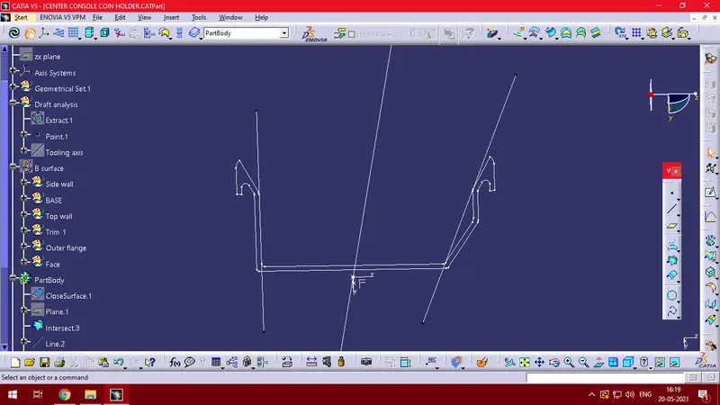
An intersection of the part is taken along its midplane and 2 lines are created on its faces which are parallel to the direction of die movement. A bisecting line is obtained from the 2 lines which forms the tooling axis.
RIB Design
Ribs provide stiffness and strength in molded parts without increasing the thickness.They also facilitate:
- Locating and arresting components of an assembly
- Provide alignment in mating parts
- Acts as stops or guides for mechanisms.
Guidelines for rib design
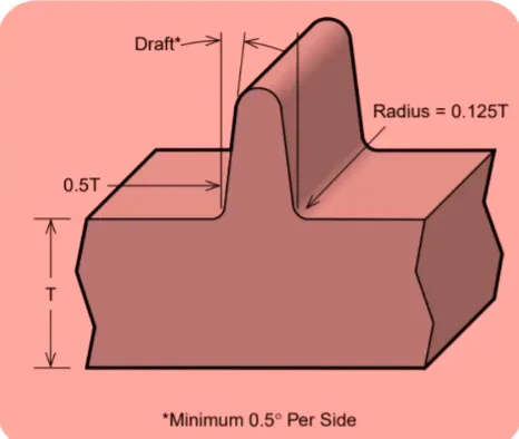
- Thickness: 0.4*Tmm
- Height: 5*Tmm
- Distance between 2 ribs : 2*T or more
- Min. thickness at the top of the rib: 0.75mm
- Location
- Quantity
- Manufacturability
Rib Nomenclature
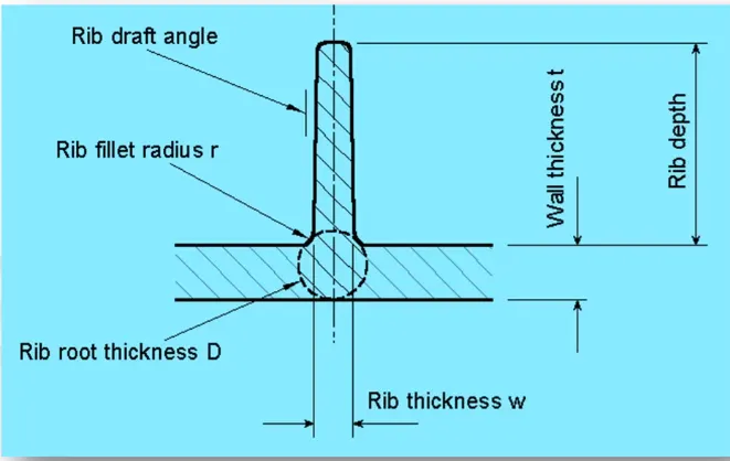
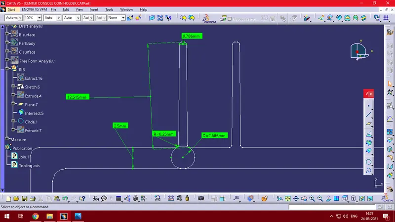
The thickness of the component is 2.5mm. Hence all the calculations for the rib are made correspondingly.