DESIGNING OF AMERICAN CHOPPER USING SOLIDWORKS
Objective:
- The objective of this project is to model individual parts of the American chopper bikes using Solidworks.
- To assemble the individual parts of the chopper.
- To create photo-realistic render of the model using photoview 360 and Solidworks Visualise.
Design methodology
| 1 |
Modelling of Individual parts of the chopper |
| 2 |
Assembling the parts of the chopper |
| 3 |
Rendering the chopper model using Photo view 360 |
| 4 |
Setting up the chopper in an environment and rendering using Solidworks Visualize |
Description of features used
- Extruded boss/base - It helps to create a 3D model/ part using a 2D sketch.
- Extrude cut - It is to remove material from a 3D model.
- Revolve boss/base - It is used to create symmetric 3D parts.
- Fillet - It is used to create round edges or faces.
- Lofted boss - It is used to generate geometry between two different cross - sections
- Dome - it is used to create a round surface.
- Split - It is used to split faces on a body.
- Trim entities - It is used to remove additional or unwanted sketches..
- Mirror - It is ised to create a mirror image of an part or sketch.
- Combine - It is used to manually combine bodies.
- Shell - It is used to define the thickness of an hollow part.
- Chamfer - It is used to make symmetrical sloping edge.
- Circular pattern - It is used to create a number of instances of a part about the diameter of the circle.
- Linear pattern - It is used to create a number of instances of a part along the specified length and direction.
- Lofted surface - It is used to generate surface between two different cross- sections.
- Filled surface - It is used to create surface between defined boundaries.
- Swept surface - It is used to create a surface from a cross - section along a path.
- Surface trim - It is used to trim unwanted surfaces.
- Surface knit - It is used to knit open edges by using a tolerance value.
- Extended surface - It is used to extend the existing surface.
Parts of American chopper
- Transmission belt
- Kickstand
- Front fender
- Rear fender
- Chain
- Oil tank
- Foot pedal
- Front wheel
- Rear wheel
- Front fork
- Chasis
- Engine
- Fuel tank
Modelling of American chopper
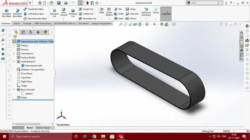
- Transmission belt:Features used - Boss extrude, fillet.
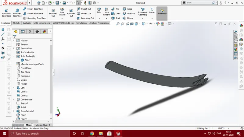
- Kickstand:
Features used:
- Loft
- Dome
- Extrude cut
- Split
- Extruded boss/base
- Fillet
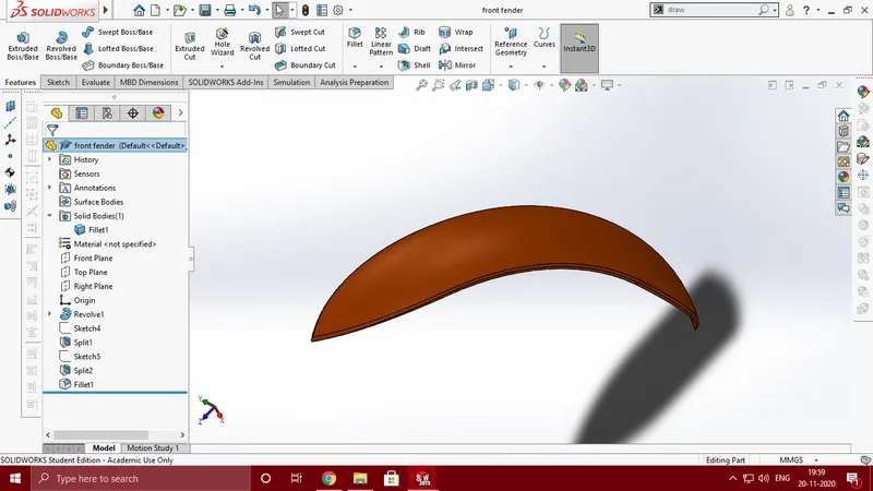
- Front fender
-
Features used
- Revolved boss/base
- Split.
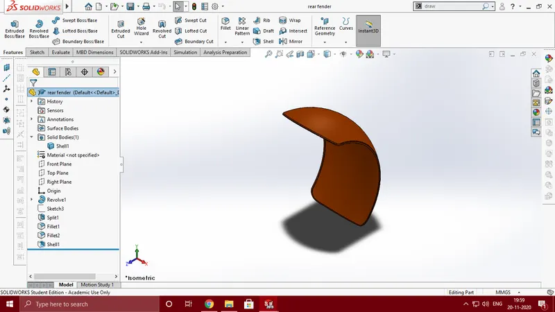
- Rear fender
Features used
- Revolved boss
- Split
- fillet
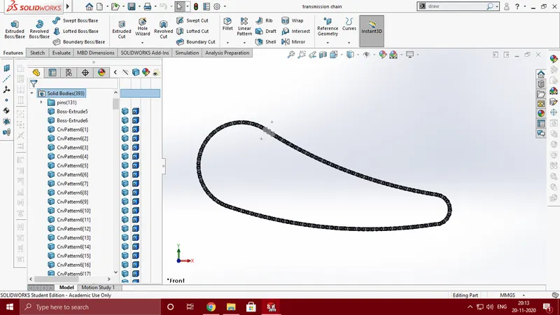
- Chain
Features used
- Extruded boss
- Curve pattern
- Fillet
- Mirror
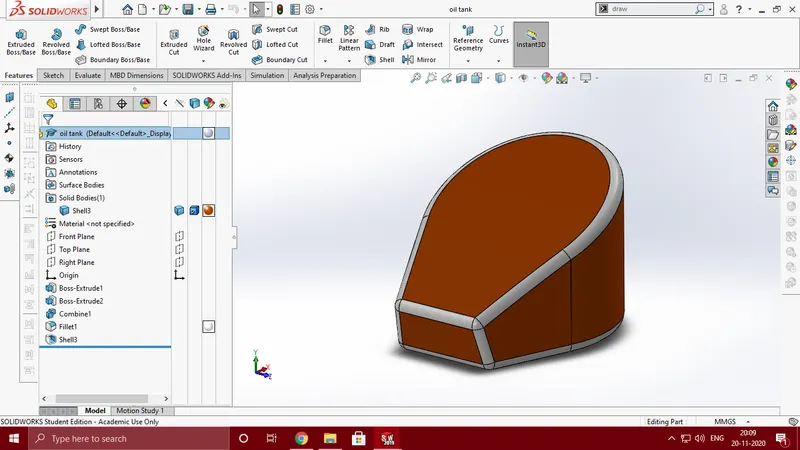
- Oil tank
Features used
- Extruded boss
- combine
- Fillet
- Shell
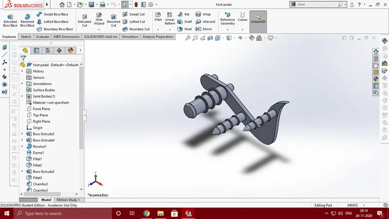
- Pedal
Features used
- Extrude
- Fillet
- Chamfer
- Dome
- Linear pattern
]
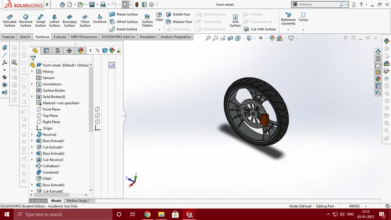
- Front wheel
Features used
- Extruded boss
- Extruded cut
- Revolve
- Fillet
- Chamfer
- Combine
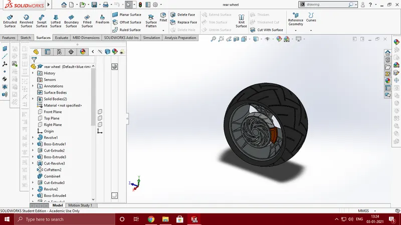
- Rear wheel
Features used
- Extruded boss
- Extrude cut
- Revolve
- Circular pattern
- Fillet
- Chamfer
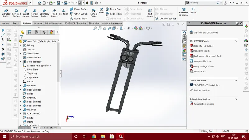
- Front fork
Features used
- Extruded boss
- Revolve
- Extrude cut
- Fillet
- Swept boss
- Projected curve
- Mirror
- Combine
- Dome
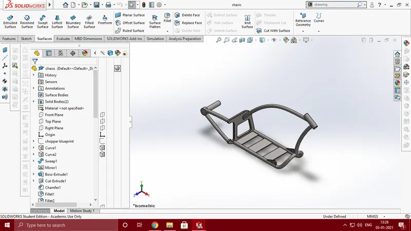
- Chasis
Features used
- Projected curve
- Sweep
- Extruded boss
- Extrude cut
- Chamfer
- Fillet
- Mirror
- Combine
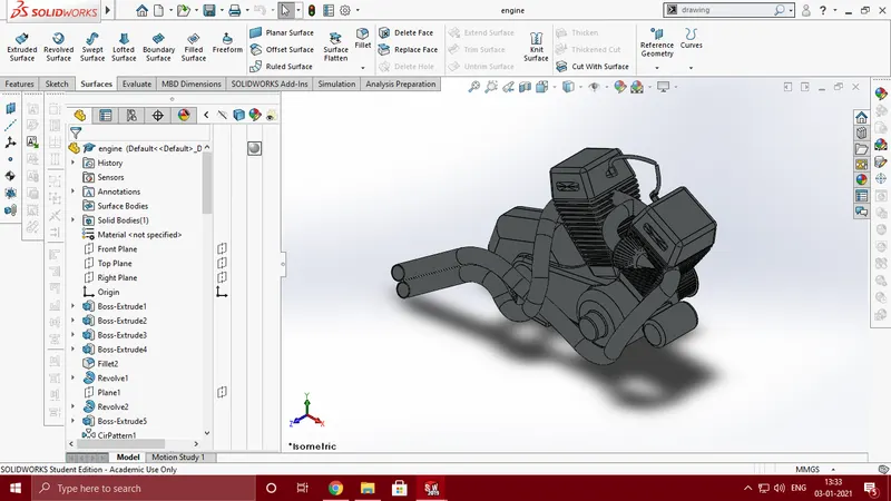
- Engine
Features used
- Projected curve
- Sweep boss
- Extruded boss
- Extrude cut
- Dome
- Chamfer
- Revolve
- Linear pattern
- Circular pattern
- Composite curve
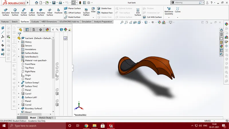
- Fuel tank
Features used
- Surface loft
- Surface knit
- Project curve
- Fillet
- Swept surface
- Split
- Mirror
- Swept cut
Assembly of American chopper
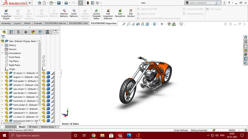
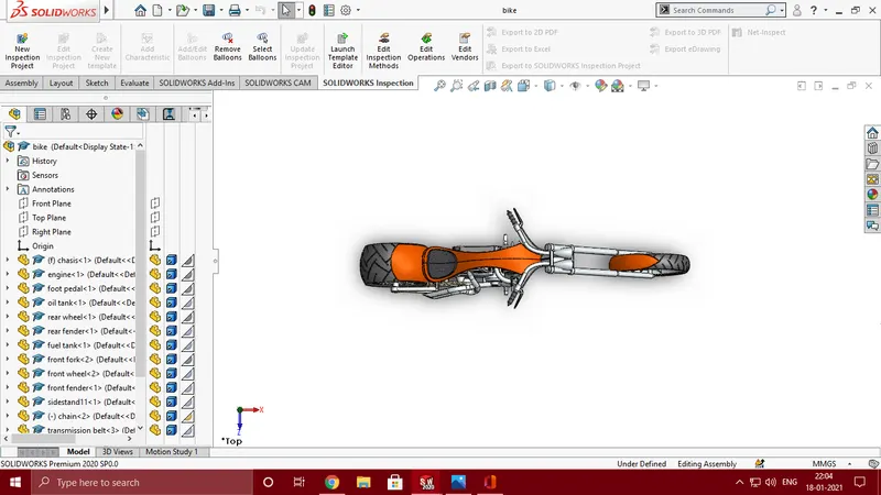
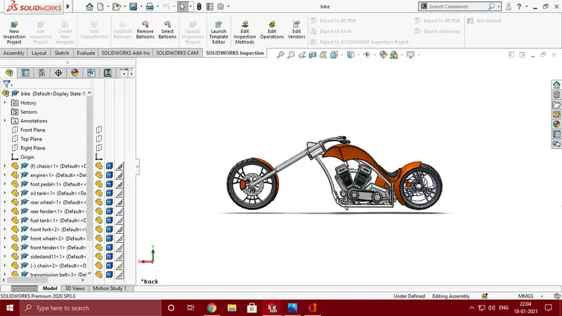
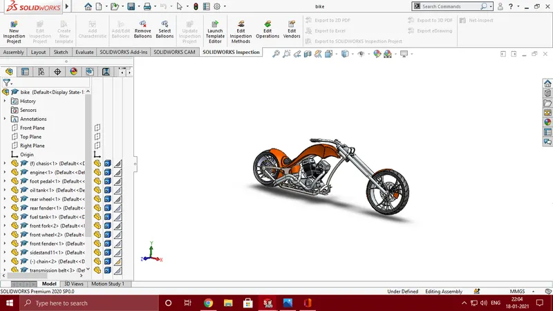
All the individual parts of the chopper are assembled by applying the necessary relations.
Features used
- Insert part/component
- Mates
Camera view
Top view
Front view

Side view
Isometric view
Rendering
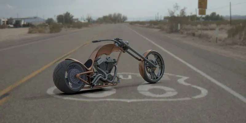
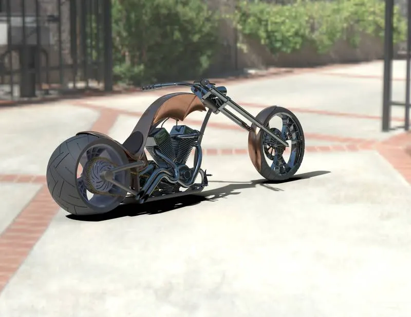
Rendering is the process of generating a photorealistic image of an 3D model.
Photo view 360 and solidworks visualise are the tools which I have used to render the American chopper bike.
Rendered images
Conclusion
- All the parts of the American chopper are modelled and assembled.
- Photorealistic renders were generated using photo – view 360 and Solidworks Visualise.