Week-11 Challenge: Braking
Aim:
- To define driving cycle, calculate the energy required for braking.
- To define electric motor can’t develop braking torque at high speed similar to starting
- To Make a MATLAB program which plots contour of given motor speed, torque and efficiency values.
Description:
1. For a defined driving cycle, calculate the energy required for braking.
Here we make the drive cycle data from an excel sheet based on the vehicle speed Vs time. And the excel Sheet drive cycle data is attached below. For our better understanding. we have plotted a graph between time and speed which is m per sec.which is converted into km per hr for our calculation purpose
Mass considered here is 1350
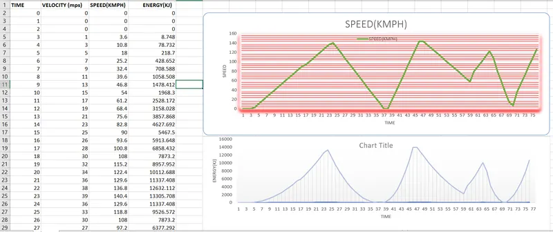
We have plotted the graph between speed vs time and also Energy vs time for our better understanding.
FORMULAS USED TO CALCULATE THE BRAKING POWER:
The Kinetic Energy which assist the Vehicle to move also gets dissipated while the braking is done. Though it depend on multiple parameters on how efficient the braking would be it can be depended upon.
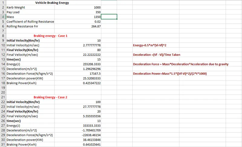
Energy=0.5*m*(Vi-Vf)^2
Deceleration =(Vf - Vi)/Time Taken
Deceleration Force = Mass*Deceleration*Acceleration due to gravity
Deceleration Power=Mass*1.5*((Vf-Vi)^2)/(2*t*1000)
Where
Vi------Initial Velocity: Here the maximum velocity obtained after braking is considered .
Vf------Final Velocity:Here the minimum velocity obtained after braking is considered .
From the above drive cycle, three different situation of deceleration are considered where energy is calculated.
First Braking= 10 - 80Km/hr in 15 sec = 0.4300733
Second Braking= 100 - 20 km/hr in 13 sec =0.648148148
Using Excel, Energy required to calculate braking are shown below
2.Why electric motor can’t develop braking torque at high speed similar to starting? How electric and mechanical brakes are coordinated?
- In braking mode, the motor acts as a generator and it converted the mechanical energy into electrical energy so it opposes the motion. The motor caan operate in both forward and also in reverse direction which is both the motoring and braking operation.
- When the motor is operated in forward direction it says that speed of motor is considered positive.The rotationof motor in the opposite direction it give reverse the speed which it is dnoted ny a negative sign.
- The rate of change in speed with respect to the time in forward direction which provides acceleration which is known as positive motor torque.Suppose in the case of retardation the torque developed by the motor is negative.
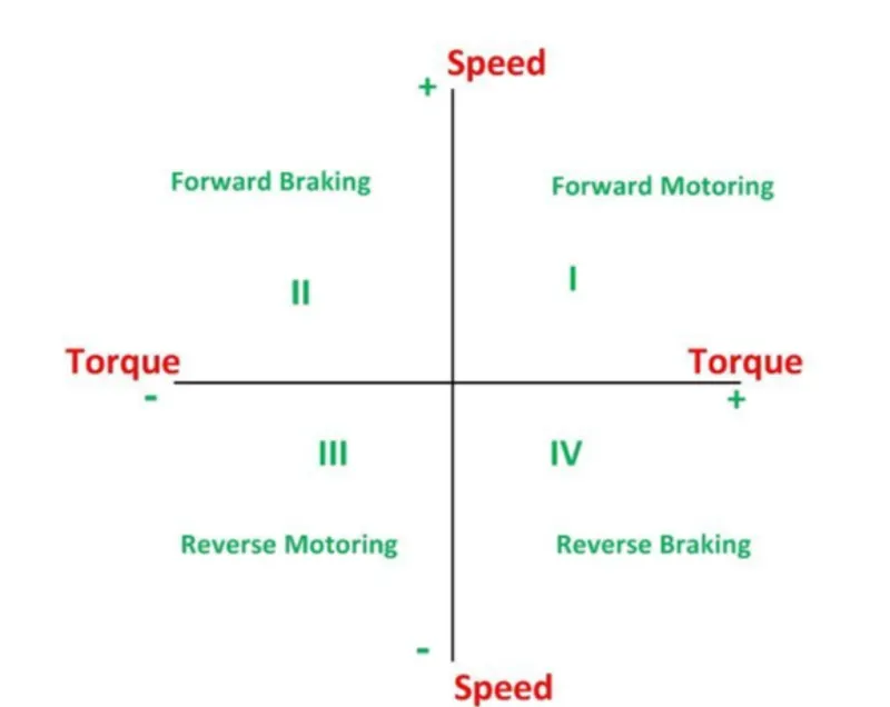
Electric motor cannot develop braking torque at high speed-Reason
Now Speed torque Characteristics of motor is shown below
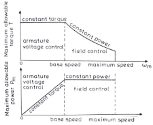
- From the first graph that till the motor reaches the critical speed it has a constant speed and it has constant torque and once it reaches the critical speed, the curve is having a down slope which is a constant power region.This graph denotes the accelerating operation of the motor. For deceleration or braking operation of the motor, this graph is mirrored down which will be hqving the speed(+ve) and torque (-ve)
- When a EV can achieve 0-100kmph in 10 sec. Acceleration operation goes this way, with low speed and high torque constant torque region is achieved which has accelerating power and by reaching the critical speed it shifts to constant region and thus it easy for an EV to reach 0-100Kmph.
- As in the breaking operation graph will be the mirrored image of above plot.So we cannot say that the motor produce 7 N-m torque for acceleration can also produce -7N-m for braking.Because we are operating above the base Speed.Thus Peak Acceleration Torque is greater than the Peak Deceleration torque. Thus for acceleration it has high torque with low speed and for deceleration it has low torque for high speed.
Electric and Mechanical brakes are coordinated
These are two brake control Strategies namely
Serial regenerative braking:
- Brakes will be applied one after the another due to series connected. Simply, one brake stratergy at a time either Regenerative braking or Mechanical Braking at a time.
- Serial regenerative braking is basically based on the combination of friction-based adjustable braking system that transfers energy to an electric motors and batteries under an integrated control strategy. The overall design of serial regenerative braking is to estimate the deceleration required and distribute the required braking force between the regenerative braking system and mechanical braking system. Serial braking system requires brake by wire system and has more consistent pedal feel one and due to good torque blending capability.
Parallel regenerative braking:
- Brakes will be applied at a time due to Parallel connected. Simply, two brake stratergy at a time both Regenerative braking and Mechanical Braking at a time.
Parallel braking system is basically based on the combination of friction-based system and the regenerative
braking system, operated in tandem without an integrated control. The regenerative braking force is calculated from the brake control unit by comparing the requested brake torque and the motor torque available. Parallel regenerative braking system requires more work in achieving good torque blending.
Electric driven Intelligent Brake developed by Nissan leaf
Technology Functionality:
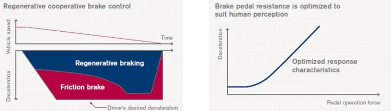
EBID(Electric driven Intelligent Brake) control the regenerative brake and friction brake to support both of these requirement. Further, it also control the reactive force from the pedal in order to unify the feeling when stepping down on the pedal and in the sense of deceleration.
3.Make MATLAB program which plots contour of given motor speed, torque and efficiency values. Attach the code as a .m file attach a screenshot of all the plots.
In a Motor having a Various types of losses happening inside.The various types of losses are
Copper Losses:
- The power lost in the resistance of the motor windings and are often called copper losses, or I²R losses, which included the stator and rotor windings copper losses
- I²R, where R is the Armature resistance and we say that Torque is proportional to Current, this Copper loss can be considered
Copper Losses=I²R
Iron Losses:
Iron Losses are nothing but Magnetic Losses,Ki*w
losses could be reduced by:
1) Increasing the length of magnetic structure and thus decreasing flux density.
2) Using thinner laminations in the magnetic structure.
3) Using silicon grades of electrical steel. In general higher the silicon content (up to 4%), the lesser
shall be the magnetic losses.
Iron Losses=Ki*w
Windage Losses:
It is due to mechanical and frictional losses experienced by the motor.It depend upon the shape and size of the motor.The following equation is given by
Windage Losses=Kw*w3
Constant Losses:
Constant losses are these losses that only occur irrespective of the load conditions and whose value will remains constant for a given machine. Mechanical losses, core losses, and shunt field copper losses are to be constant losses.
Total Losses:
The total of above four is said to be total losses
Total Losses=I²R+Ki*w +Constant losses+Kw*w3
MATLAB program which plots contour of given motor speed, torque and efficiency values.
clear all
close all
clc
%Losses Coefficient
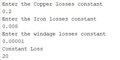
K_C=input("Enter the Copper losses constant\n");
K_I=input("Enter the Iron losses constant\n");
K_W=input("Enter the windage losses constant\n");
C_L=input("Constant Loss\n");
% x axis will represent the speed(rad/sec)
X=linspace(1,1000);
% y axis will represent the torque value (N-m
Y=linspace(1,200);
%meshing the speed & torque
[x,y]=meshgrid(X,Y);
%Copper loss
A=K_C.*(y.^2);
%windage loss
B=K_W.*(x.^3);
%Iron loss
C=K_I.*(x);
%output power
O_P=(y.*x);
%Input Power
I_P =A+B+C+O_P+C_L;
%Efficiency
E=O_P./I_P;
%Efficieny plotted with reference of V value
V = [0.60,0.64,0.68,0.70,0.72,0.75,0.77,0.80,0.82,0.85,0.88,0.90,0.92,0.94,0.96];
box off
grid off
contour(x,y,E,V)
xlabel('speed rad/sec')
ylabel('Torque N-m')
title("Speed Torque Charcteristics");
hold on
V = [8000,9000];
contour(x,y,O_P,V)
Explanation for the Program:
- Assign Input of Speed and Torque in an array using linspace.
- Mesh the Speed and Torque Values using 'meshgrid' command
- Calculate the o/p power
- Calculating the Copper Loss, Iron Loss, Windage Loss, Constant motor loss using this formula
- Calculating Input power by adding Output Power and Four Losses
- Find out the Efficiency
- Now set the efficiency for which a contour will be plotted. The range of contour efficiency is to plot from 60% to 96% efficiency
- Plot the Contour Efficiency using 'contour' command and plot Speed, Torque, Efficiency and V
- Now plot a contour of power output . Plotting contour for different Kw Motor
- Run the Program and get the Motor Speed-Torque Efficiency contour plot.
Input:
Result:
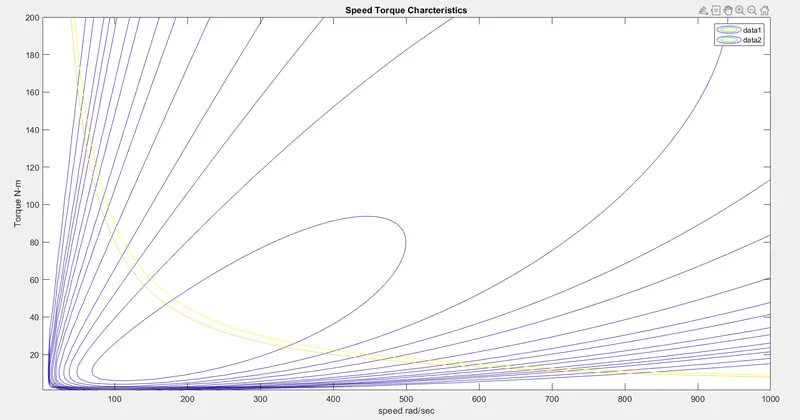
The above plot shows the Motor Speed-Torque Efficiency Contour Plot. A point is denoted innermost contour line is group of efficiencies which is highest value of the efficiency as 96% because where the height is maximum and another point is denoted outermost contour line is contain group of efficiencies which is the lowest value of efficiency as 70% because where the height reduces.Increasing efficiencie order as going inward and Decreasing efficiency order as going outward. The yellow line shows the 8Kw and 10Kw Power.
Conclusion:
Hence we find out the driving cycle to calculate the energy required for braking and also electric motor can’t develop braking torque at high speed similar to starting finally we Make a MATLAB program which plots contour of given motor speed, torque and efficiency values.