Week 10 - Challenge 3 - Door Trim Lower with Engineering Features
Aim:
To A Create the DOOR TRIM LOWER Plastic component through the given Class-A surface. Also, Create the Heat Stakes and the locators considering the design rules mentioned in the video for the door applique.
Objective:
The main aim of this challenge is to create a solid body of 'Door Trim Lower' with the help of the closed surface method by using the 'Generative shape design' workbench in CATIA V5. Performing the 'Draft Analysis' on the solid part body of the Door trim.
Take the Thickness of the component to be 2.5 m
Given class A surface:
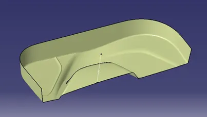
In the given task, we are required to thicken the Class A surface. However, before proceeding with the thickening process, it is essential to observe the Class A surface carefully. Class A surfacing is considered an art in front of engineering and involves the process of bringing styling into digital life.
To ensure a successful thickening process, it is crucial to thoroughly examine the Class A surface, as depicted in the figure below.
Tooling axis:
The tooling axis is formed by rotating Angle 1 about the x-axis, followed by rotating Angle 2 about the y-axis. Additionally, there is an Angle 1 rotation about the Z-axis, followed by an Angle 2 rotation about the X-axis to establish the tool axis.
In practical applications involving the removal of metal from the core and cavity, we require a center of the surface known as the tooling axis. To create the tooling axis, first, create dummy lines on a bush or hole walls and then intersect them, as shown in the figure below.
<!--[endif]-->
Draft analysis for class A surface:
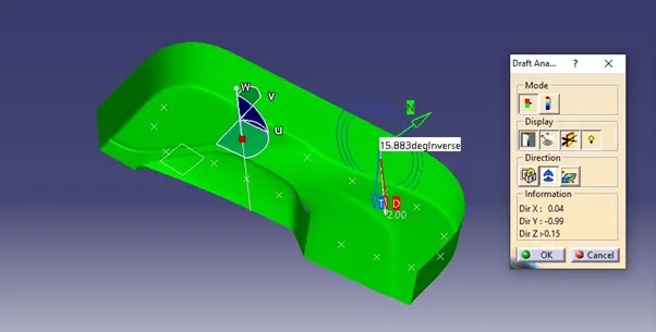
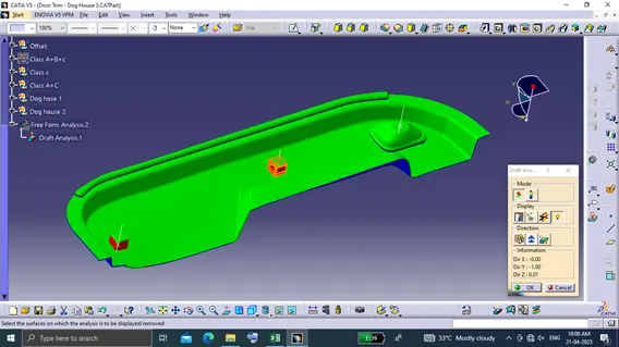
Before creating solids and B-side features for Class A surfaces, it is essential to perform a draft analysis check. This check helps ensure that the surfaces have the required draft angles for proper moldability.
To conduct the draft analysis, I first align the compass to the tooling axis, which is crucial for maintaining the desired directionality of the surface. Then, I apply a 3-degree draft angle for the green color in the color bar. When the Class A surface is entirely highlighted in green
color, it indicates that the draft angle has been correctly applied, and the surface meets the necessary criteria.
If the Class A surface is not fully highlighted in green color during the draft analysis, it signifies that the draft angle might be inadequate or inconsistent on that particular surface. In such cases, adjustments need to be made to ensure that the draft angle is appropriately applied to achieve the desired moldability for the Class A surface.
<!--[endif]-->
Class B surface:
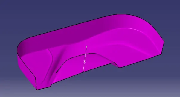
To create the Class B surface, follow these steps:
<!-- [if !supportLists]-->1. <!--[endif]-->Offset the Class A surface inside as per the specified thickness requirement. In this case, the thickness is 2.5mm, so offset the Class A surface 2.5mm inside. This will create a new surface parallel to the original Class A surface.
<!-- [if !supportLists]-->2. <!--[endif]-->After creating the offset surface, observe any patches or gaps that may appear on the offset surface. These patches are formed due to the presence of fillets on the Class A surface.
<!-- [if !supportLists]-->3. <!--[endif]-->To cover the patches on the offset surface, use the multi-section surfaces command. This command allows you to extract the boundaries of the patches.
<!-- [if !supportLists]-->4. <!--[endif]-->Once you have extracted the patch boundaries, use them to cover the patches on the offset surface effectively. This process will ensure a continuous and smooth surface without any gaps.
<!-- [if !supportLists]-->5. <!--[endif]-->After covering all the patches, join them with the offset surface to create a unified surface that replicates the Class A surface. The result will be a Class B surface that maintains the specified thickness and covers any patches caused by fillets on the original Class A surface.
<!--[endif]-->
Class C surface:
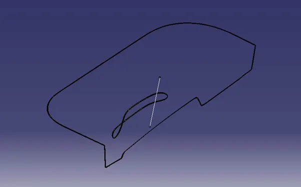
When constructing the Class C surface, it is important to consider that Class C allows more imperfections compared to Class A or B. Class C surfaces are typically specified for interior surfaces that are not readily visible or surfaces that will be covered by another part when assembled. Due to their lower visibility requirements, they can tolerate some level of imperfections.
The process of constructing the Class C surface involves the following steps:
<!-- [if !supportLists]-->1. <!--[endif]-->Take the boundaries of the Class A surface.
<!-- [if !supportLists]-->2. <!--[endif]-->Sweep these boundaries to create a new surface that extends over the desired area.
<!-- [if !supportLists]-->3. <!--[endif]-->Trim any excess parts of the swept surface that extend beyond the intended boundaries.
<!-- [if !supportLists]-->4. <!--[endif]-->Join the trimmed swept surfaces together to form a continuous and unified Class C surface.
<!--[endif]-->
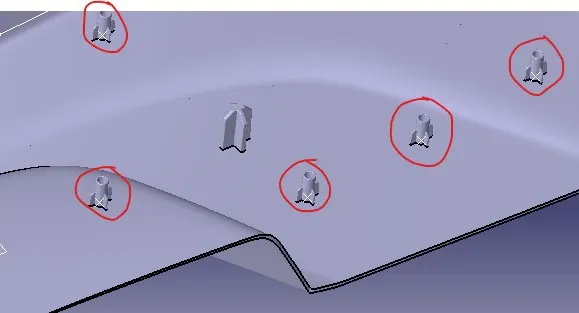
Heat stakes:
Heat staking, also known as thermoplastic staking, is a process used for joining two dissimilar materials together. The primary purpose of heat staking is to create a strong bond between plastic components. This process involves local heating and cooling of the plastic components.
<!--[endif]-->
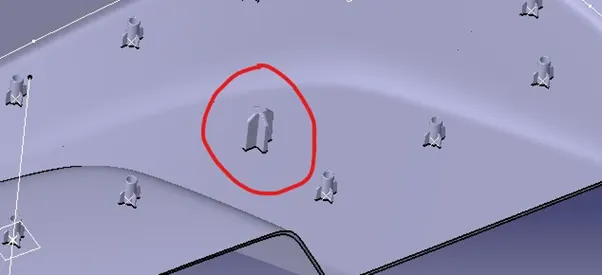
Locators:
Locators are devices or components used in various manufacturing and assembly processes to precisely position and align parts, components, or tools. They are essential for ensuring accuracy, repeatability, and efficiency in the production of complex products or assemblies.
<!--[endif]-->
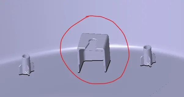
Dog House:
<!--[endif]-->
Draft analysis:
<!--[endif]-->
Conclusion:
Created class A and Class B surface from class B surface. The engineering features like locators, dog house, heat stakes and ribs are created according to the standards. Draft analysis of entire model has been done