Week 12- Final project
Objective:
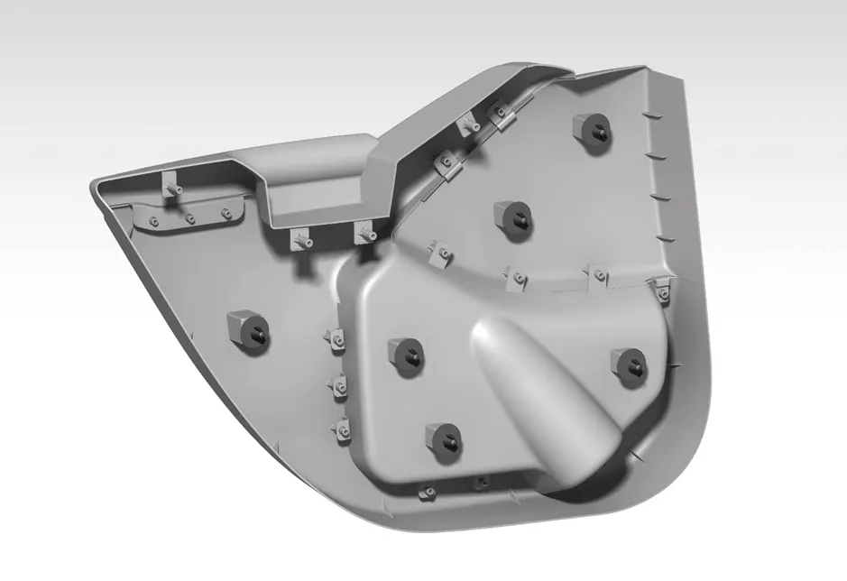
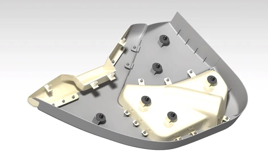
The objective of this project is to create half of the door trim panel in CATIA-V5 using the provided Class-A surface.
Abstract:
This report contains a brief overview of design rules and the approach taken to achieve the final plastic product. It includes a draft analysis report for all the Class-A surfaces, as well as details on the procedure for creating the Class-B and Class-C surfaces.
Approach:
Our primary approach to creating a plastic model from the Class-A surface involves the following steps:
<!-- [if !supportLists]-->1. <!--[endif]-->Perform draft analysis.
<!-- [if !supportLists]-->2. <!--[endif]-->Establish tooling axis.
<!-- [if !supportLists]-->3. <!--[endif]-->Create the Class-B surface.
<!-- [if !supportLists]-->4. <!--[endif]-->Develop the Class-C surface.
<!-- [if !supportLists]-->5. <!--[endif]-->Trim all components together to form a solid structure.
Class-A Surface:
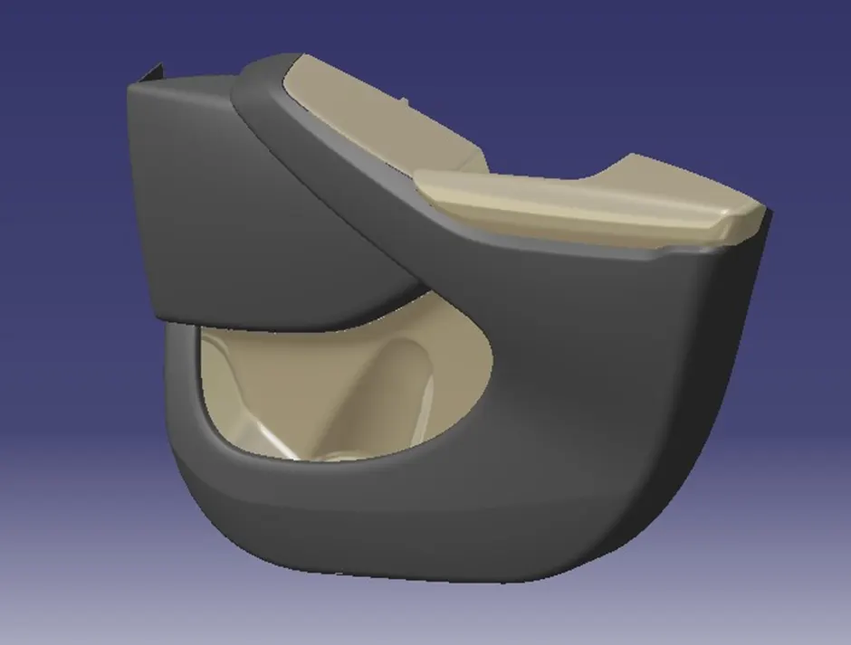
In the automotive industry, multiple teams collaborate on different components of a vehicle. For example, a car is not solely designed by a single designer but involves various teams responsible for various aspects. This distribution of tasks is common across all departments within the industry. In this project, we have been provided with a Class-A surface, which has been designed in software like Autodesk Alias by a Class-A designer. This surface focuses on aesthetics and requires significant time, effort, and expertise to ensure its continuity and smooth surface model. Therefore, as plastic designers, we are not permitted to make any alterations to the Class-A surface when it is provided as input.
Class A Suraface Upper Subtrate:
Class A Suraface Arm rest:
Class A Surface Lower substrate:
Class A Surface Upper Substrate:
Class B Surface:
<!--[endif]-->Class C Surface:
Tooling axis
Tooling axis is the axis along which the core and cavity opens and closes. It is very important to define the tooling axis in the first step while designing a component as it is the main component which helps us to run draft analysis on class-A at initial stage to see if we can move ahead. Also for later stage, tooling axis is the direction along which class-C surface and the draft to the components is given.
In this model we have a tooling axis in the perpendicular direction to the entire door trim that is y-direction in the model. It is very evident that switch bezel will require a side core, so another tooling direction is made specifically for switch bezel. Apart from these two tooling axes we also have a side core tooling axis for dog house.
Draft analysis
First step before starting the model should always be to check is the surface has enough draft that it will not create any problems while ejecting from the mold. This seems like a big task as we have to foresee something that will come at very later stage. But this is done by a small process called draft analysis. This analysis tells us whether our component will be safely ejected in the tooling axis we have provided. Some components require side core where there are under undercuts, holes or projections on the side walls, so for this we need a different tooling axis and a different analysis is required to check those areas. Draft analysis shows color codes which are defined by the user for different values which also are defined by the user. These colors help us to analysis if the component is clearing the analysis and we are good to go ahead or not. In case the component fails the analysis for class-A then we have to submit the draft analysis report to the higher authority so that the surface of the component can be improved. Failing analysis simply means that the component does not have the required draft value it must have. In case our solid model which we develop, fails the analysis at some parts then we have to correct it ourselves.
We have to make sure that our entire model is green which means it is clearing the analysis. So we have to run analysis for class-A, solid model and other B-side features as every single component, regardless of its size should be ejected safely from the core.
Our goal is to ensure that our entire model shows up as green, indicating successful clearance of the analysis. This means that every single component, regardless of its size, should be able to eject safely from the mold core.
Sequence of Operations to generate CAD Model of a plastic component:
<!-- [if !supportLists]-->1. <!--[endif]-->Extracting the input Class-A surface into different parts of Assembly.
<!-- [if !supportLists]-->2. <!--[endif]-->Looking for defects in Class-A surface.
<!-- [if !supportLists]-->3. <!--[endif]-->Improving Class-A surface by patching defects.
<!-- [if !supportLists]-->4. <!--[endif]-->Improving Class-A surface as per Master section.
<!-- [if !supportLists]-->5. <!--[endif]-->Creating Tooling Axis.
<!-- [if !supportLists]-->6. <!--[endif]-->Creating Class-B surface.
<!-- [if !supportLists]-->7. <!--[endif]-->Creating Class-C surface.
<!-- [if !supportLists]-->8. <!--[endif]-->Creating a Closed Body.
<!-- [if !supportLists]-->9. <!--[endif]-->Creating Dog House as per Master Section and OEM standard design Rules.
<!-- [if !supportLists]-->10. <!--[endif]-->Creating Locator as per Master Section.
<!-- [if !supportLists]-->11. <!--[endif]-->Creating Ribs as per requirement.
<!-- [if !supportLists]-->12. <!--[endif]-->Draft Analysis.
<!-- [if !supportLists]-->13. <!--[endif]-->Adding Draft as per requirement.
<!-- [if !supportLists]-->14. <!--[endif]-->Creating Side core Tooling Axis.
Designing of plastic component for given door trim panel class-a surface:
Door Trim Panel consists of the following Components.:
<!-- [if !supportLists]-->1. <!--[endif]-->Door Arm-Rest.
<!-- [if !supportLists]-->2. <!--[endif]-->Upper Map Pocket.
<!-- [if !supportLists]-->3. <!--[endif]-->Lower Map Pocket.
<!-- [if !supportLists]-->4. <!--[endif]-->Lower Substrate.
<!-- [if !supportLists]-->5. <!--[endif]-->Upper Substrate.
<!-- [if !supportLists]-->6. <!--[endif]-->Flanges.
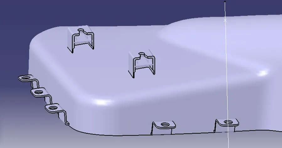
<!-- [if !supportLists]-->7. <!--[endif]-->Heat stakes and Dog Houses.
<!-- [if !supportLists]-->8. <!--[endif]-->Snap Fits.
Door Arm-Rest
The front door armrest in a car is typically a central feature that can be folded away based on user preference. It often includes a storage compartment and, in some cases, cup holders. Additionally, it may serve as the location for controls related to non-essential vehicle functions, such as climate control or window motors.
Integral Map Pocket:
In this design, the map pocket is integrated into the door trim panel itself. This is achieved by creating a projection outward toward the passenger compartment, which forms the storage space for the map pocket. A separate panel is then attached to the rear outboard surface of the trim panel, effectively enclosing the map pocket within the door trim. This type of map pocket protrudes into the passenger compartment and is a part of the door trim panel.
Lower Substrate:
In this configuration, the map pocket is recessed within the door assembly. The storage compartment of the map pocket is typically situated between the trim panel and the outer metal panel of the vehicle door. An aperture or opening in the door trim panel defines the access point to the map pocket. This design is typically created using a separate map pocket assembly, which is fastened to the rear surface of the trim panel. The map pocket assembly consists of a front portion and a separate rear portion, which are connected to form the map pocket assembly and enclose the storage compartment. The rear portion serves as the rear wall of the map pocket assembly, while the front portion defines the lower front wall and a pair of side walls. The space above the lower front wall remains generally open, allowing access to the storage compartment. The map pocket assembly is attached to the rear surface of the door trim panel in a way that aligns the opening of the map pocket with an opening formed in the door trim panel, providing access to the map pocket.
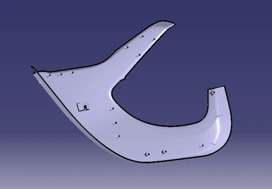
Upper Substrate:

Designing B-Side Features:
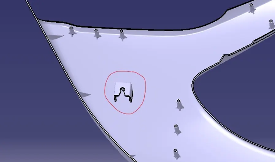
Dog House:
The primary function of the dog house is to prevent sink marks on the surface. However, it serves other purposes as well, such as accommodating mating parts at greater distances without the need for excessively tall screw bosses. This approach not only addresses screw boss height issues but also ensures perpendicular screw bosses.
<!-- [if !supportLists]-->· <!--[endif]-->Minimum height: Less than 6mm causes steel condition.
<!-- [if !supportLists]-->· <!--[endif]-->Minimum width: 3:1 ratio of steel width to height. But 2:1 is preferred.
<!-- [if !supportLists]-->· <!--[endif]-->Draft: minimum 1.5deg.
<!-- [if !supportLists]-->· <!--[endif]-->Sink saver: height= 40% of nominal thickness. Width= 3.0mm-6.0mm.
<!-- [if !supportLists]-->· <!--[endif]-->Optimal radius:25mm
 \
\
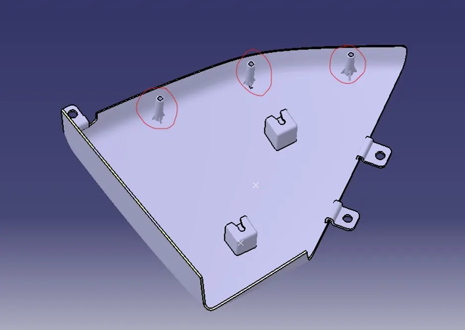
Screw Boss:
Screw bosses play a crucial role in mating two parts and accepting threaded fasteners like screws. To ensure effective screw boss design, consider the following general guidelines
<!-- [if !supportLists]-->· <!--[endif]-->Draft: 5 deg on each walls.
<!-- [if !supportLists]-->· <!--[endif]-->Wall thickness: 40% of the nominal wall thickness i.e. 0.4*t where t is the wall thickness which is 2.5mm in this case.
<!-- [if !supportLists]-->· <!--[endif]-->Height/diameter: 3:1 steel but 2:1 is preferred.
<!-- [if !supportLists]-->· <!--[endif]-->Radius of the fillet: minimum 0.25mm.
<!-- [if !supportLists]-->· <!--[endif]-->Boss gussets (rib like structure giving strength to the screw boss) must meet ribs guidelines.
<!-- [if !supportLists]-->· <!--[endif]-->Avoid merging the screw-boss into wide wall.
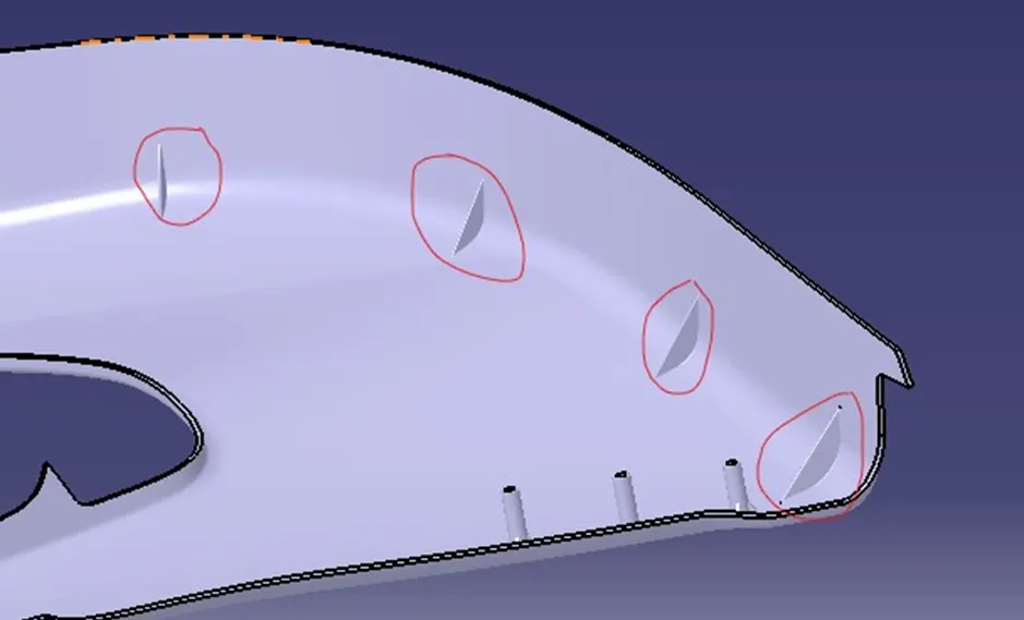
Ribs and Gussets:
Ribs and gussets are design elements used to enhance the stiffness and strength of a structure without increasing the overall wall thickness of the model. They provide several benefits, including:
<!-- [if !supportLists]-->· <!--[endif]-->Stiffness and Strength
<!-- [if !supportLists]-->· <!--[endif]-->Weight Reduction
<!-- [if !supportLists]-->· <!--[endif]-->Minimizing Material Usage
<!-- [if !supportLists]-->· <!--[endif]-->Preventing Warping
<!-- [if !supportLists]-->· <!--[endif]-->Enhancing Moldability
<!-- [if !supportLists]-->· <!--[endif]-->Increasing Load-Bearing Capacity
Heat Stacks:
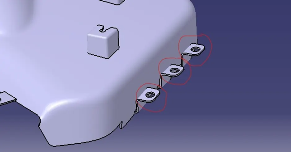
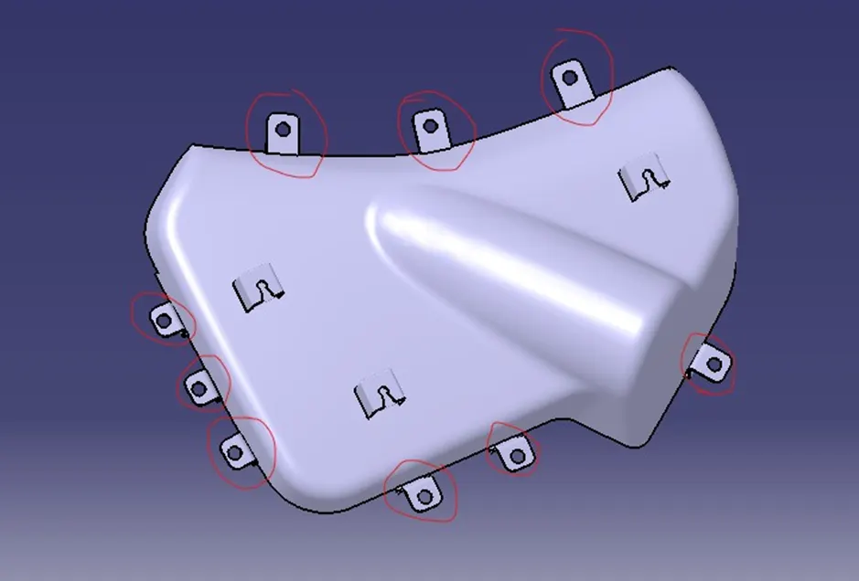
Attachment Flange:
<!--[endif]-->Assembly: